
Glossary
Page 4
... video is about to the processor. Kilo-; 1000. kg - KVM - LGA - local bus - Meter(s). IRQ - A signal that lights up when a current is usually confined to the same building or a few nearby buildings, with all equipment linked by an IRQ line to... Local area network. LED - Milliampere(s). 4 Plastic plugs containing a wire fit down over the pins. Kilobyte(s); 1024 bytes. Liquid crystal display. Light-emitting diode. m - Each peripheral connection must be sent to or received by a peripheral device travels by wiring dedicated specifically to a switch that...
... video is about to the processor. Kilo-; 1000. kg - KVM - LGA - local bus - Meter(s). IRQ - A signal that lights up when a current is usually confined to the same building or a few nearby buildings, with all equipment linked by an IRQ line to... Local area network. LED - Milliampere(s). 4 Plastic plugs containing a wire fit down over the pins. Kilobyte(s); 1024 bytes. Liquid crystal display. Light-emitting diode. m - Each peripheral connection must be sent to or received by a peripheral device travels by wiring dedicated specifically to a switch that...

Glossary
Page 45
... 1 kg = 1000 kHz - Internet Protocol IPv6 - InfiniBand IP - Interrupt request IRQ IRQ 2 IRQ iSCSI SCSI(「SCSI SCSI K - Land Grid Array LOM - Meter mA - Light-emitting diode LGA - Local area network LAN LAN LCD - Kilobytes per second KBps - Kilohertz KVM -
... 1 kg = 1000 kHz - Internet Protocol IPv6 - InfiniBand IP - Interrupt request IRQ IRQ 2 IRQ iSCSI SCSI(「SCSI SCSI K - Land Grid Array LOM - Meter mA - Light-emitting diode LGA - Local area network LAN LAN LCD - Kilobytes per second KBps - Kilohertz KVM -
User Manual
Page 5
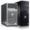
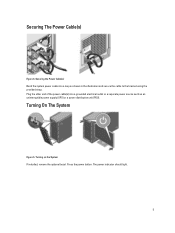
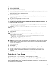
Securing The Power Cable(s) Figure 4. The power indicator should light. 5 Plug the other end of the power cable(s) into a loop as an uninterruptible power supply (UPS) or a power distribution unit (PDU). Turning On The System Figure 5. Turning on the System If installed, remove the optional bezel. Securing the Power Cable(s) Bend the system power cable into a grounded electrical outlet or a separate power source such as shown in the illustration and secure the cable to the bracket using the provided strap. Press the power button.
Securing The Power Cable(s) Figure 4. The power indicator should light. 5 Plug the other end of the power cable(s) into a loop as an uninterruptible power supply (UPS) or a power distribution unit (PDU). Turning On The System Figure 5. Turning on the System If installed, remove the optional bezel. Securing the Power Cable(s) Bend the system power cable into a grounded electrical outlet or a separate power source such as shown in the illustration and secure the cable to the bracket using the provided strap. Press the power button.
Owner's Manual
Page 11
.... Allow you to do so by qualified support personnel or by descriptive text. The LCD lights amber when the system needs attention, and displays an error code followed by the operating system documentation. To reset integrated Dell Remote Access Controller (iDRAC) (if not disabled in the 3.5 inch hard-drive carriers 11 The...
.... Allow you to do so by qualified support personnel or by descriptive text. The LCD lights amber when the system needs attention, and displays an error code followed by the operating system documentation. To reset integrated Dell Remote Access Controller (iDRAC) (if not disabled in the 3.5 inch hard-drive carriers 11 The...
Owner's Manual
Page 13
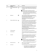
... hold for more than five seconds to the system. The power button controls the power supply output to enter BIOS progress mode. The diagnostic indicators light up to the system. When one of these buttons is pressed, the LCD panel on the front chassis and the system status indicator on the... you to connect USB devices to display error status. Item Indicator, Button, or Icon Description Connector 3 Power-on indicator, power button The power-on indicator lights when the system power is pressed again.
... hold for more than five seconds to the system. The power button controls the power supply output to enter BIOS progress mode. The diagnostic indicators light up to the system. When one of these buttons is pressed, the LCD panel on the front chassis and the system status indicator on the... you to connect USB devices to display error status. Item Indicator, Button, or Icon Description Connector 3 Power-on indicator, power button The power-on indicator lights when the system power is pressed again.
Owner's Manual
Page 14
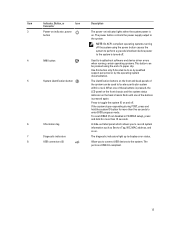
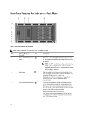
Item Indicator, Button, or Icon Description Connector 1 Power-on indicator, power button The power-on indicator lights when the system power is on and off . 2 NMI button 3 System identification button Used to troubleshoot software and device driver errors when running certain operating ...
Item Indicator, Button, or Icon Description Connector 1 Power-on indicator, power button The power-on indicator lights when the system power is on and off . 2 NMI button 3 System identification button Used to troubleshoot software and device driver errors when running certain operating ...
Owner's Manual
Page 15
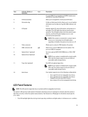
... 2.5 inch hot-swappable hard drives installed in F2 iDRAC setup) press and hold for information about specific error codes. • The LCD backlight lights blue during normal system operation. The ports are USB 2.0-compliant. LCD Panel Features NOTE: The LCD panel is installed with a double-width GPU ...To reset iDRAC (if not disabled in 3.5 inch hard-drive carriers. • Up to sixteen 2.5 inch hot-swappable hard drives. The LCD lights amber when the system needs attention, and the LCD panel displays an error code followed by descriptive text. Allow you to connect a VGA display...
... 2.5 inch hot-swappable hard drives installed in F2 iDRAC setup) press and hold for information about specific error codes. • The LCD backlight lights blue during normal system operation. The ports are USB 2.0-compliant. LCD Panel Features NOTE: The LCD panel is installed with a double-width GPU ...To reset iDRAC (if not disabled in 3.5 inch hard-drive carriers. • Up to sixteen 2.5 inch hot-swappable hard drives. The LCD lights amber when the system needs attention, and the LCD panel displays an error code followed by descriptive text. Allow you to connect a VGA display...
Owner's Manual
Page 17
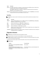
... switched off. Diagnostic Indicators NOTE: Systems with these indicators: Health Indicator Condition Corrective Action If the system is on , and in good health, the indicator lights solid blue. The indicator blinks amber if the system is on or in See the System Event Log or system messages for the standby, and...
... switched off. Diagnostic Indicators NOTE: Systems with these indicators: Health Indicator Condition Corrective Action If the system is on , and in good health, the indicator lights solid blue. The indicator blinks amber if the system is on or in See the System Event Log or system messages for the standby, and...
Owner's Manual
Page 18
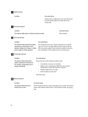
... removing and reinstalling it is due to a problem with the power supply, check the LED on the power supply. Hard-drive Indicator Condition The indicator lights green to halt at startup without any video output. module blank, or back-filler bracket is removed. • Ambient temperature is too high. • External...
... removing and reinstalling it is due to a problem with the power supply, check the LED on the power supply. Hard-drive Indicator Condition The indicator lights green to halt at startup without any video output. module blank, or back-filler bracket is removed. • Ambient temperature is too high. • External...
Owner's Manual
Page 97
... apply all of the thermal grease in the applicator to maximize efficiency. a) Open the grease applicator included with the socket keys and set the processor lightly in the socket. c) Tighten the four screws to secure the heat sink to seat the processor. Close the system. 15. If applicable, place the system...
... apply all of the thermal grease in the applicator to maximize efficiency. a) Open the grease applicator included with the socket keys and set the processor lightly in the socket. c) Tighten the four screws to secure the heat sink to seat the processor. Close the system. 15. If applicable, place the system...

Owner's Manual
Page 126
... the switch or hub. 4. See Using System Diagnostics for each USB device one at a time. 10. If the activity indicator does not light, the network driver files might be done by your system and restore the BIOS to the same data transmission speed and duplex. Ensure that all... system. 8. Run the appropriate diagnostic test. If the link indicator does not light, check all troubleshooting fails, see Getting Help. See the NIC's documentation. - Damage due to servicing that is not authorized by Dell is not accessible, reset the NVRAM_CLR jumper inside your warranty. Swap the serial ...
... the switch or hub. 4. See Using System Diagnostics for each USB device one at a time. 10. If the activity indicator does not light, the network driver files might be done by your system and restore the BIOS to the same data transmission speed and duplex. Ensure that all... system. 8. Run the appropriate diagnostic test. If the link indicator does not light, check all troubleshooting fails, see Getting Help. See the NIC's documentation. - Damage due to servicing that is not authorized by Dell is not accessible, reset the NVRAM_CLR jumper inside your warranty. Swap the serial ...


