Getting Started Guide
Page 6
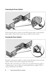
Securing the Power Cable(s) Bend the system power cable(s) as an uninterrupted power supply (UPS) or a power distribution unit (PDU). 4 Getting Started With Your System Plug the other end of the power cables into a grounded electrical outlet or a separate power source such as shown in the OFF postion before connecting the power cables. Connect the system's power cable(s) to the bracket using the provided strap. Connecting the Power Cable(s) Ensure that the power switch is in the illustration and secure the cable(s) firmly to the system.
Securing the Power Cable(s) Bend the system power cable(s) as an uninterrupted power supply (UPS) or a power distribution unit (PDU). 4 Getting Started With Your System Plug the other end of the power cables into a grounded electrical outlet or a separate power source such as shown in the OFF postion before connecting the power cables. Connect the system's power cable(s) to the bracket using the provided strap. Connecting the Power Cable(s) Ensure that the power switch is in the illustration and secure the cable(s) firmly to the system.
Getting Started Guide
Page 10
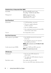
Back-Plane Board Connectors Sensors • 12 SAS hard-drive connectors • Two power supply/cooling fan module connectors • Two sets of Independent Disks (RAID) Controller Host-based RAID support using PowerEdge™ RAID controller H800 Management RAID management using Dell OpenManage™ Server Administrator 6.2 or later. One 6-pin UART mini-DIN connector...
Back-Plane Board Connectors Sensors • 12 SAS hard-drive connectors • Two power supply/cooling fan module connectors • Two sets of Independent Disks (RAID) Controller Host-based RAID support using PowerEdge™ RAID controller H800 Management RAID management using Dell OpenManage™ Server Administrator 6.2 or later. One 6-pin UART mini-DIN connector...

Getting Started Guide
Page 11
...A at +5 V Up to locate a system within a rack. Used to switch the system between unified and split mode operation. Power Supplies AC power supply (per power supply) Wattage 600 W Voltage 100-240 VAC (8.6 A-4.3 A) Heat dissipation 188 W Maximum inrush current Under typical line conditions and over ...the entire system ambient operating range, the inrush current may reach 55 A per power supply for power supply status, power supply/fan fault, and AC status Switch System identification button Mode switch Located on the front control panel. LED Indicators (...
...A at +5 V Up to locate a system within a rack. Used to switch the system between unified and split mode operation. Power Supplies AC power supply (per power supply) Wattage 600 W Voltage 100-240 VAC (8.6 A-4.3 A) Heat dissipation 188 W Maximum inrush current Under typical line conditions and over ...the entire system ambient operating range, the inrush current may reach 55 A per power supply for power supply status, power supply/fan fault, and AC status Switch System identification button Mode switch Located on the front control panel. LED Indicators (...

Setting Up Your Dell PowerVault Storage Enclosure
Page 1
... redundant paths. Split mode LED 2. Debug port 7. Out port link status LED 13. Power switches (2) Locating Your System Service Tag • Your system is also located at support.dell.com/manuals. 2 Selecting the Operating Mode Front-Panel Features Dell PowerVault MD1200 3 2 4 1 Dell PowerVault MD1220 3 4 5 5 2 1 8 Back-Panel Features 1 2 3 6 8 ...to the Host Server(s)" below lists the drives that are found on support.dell.com/manuals. Power LED 3. Power supply/cooling fan fault LED 3. Power supply/cooling fan module 1 5. SAS port (In) 9. The enclosure bus ...
... redundant paths. Split mode LED 2. Debug port 7. Out port link status LED 13. Power switches (2) Locating Your System Service Tag • Your system is also located at support.dell.com/manuals. 2 Selecting the Operating Mode Front-Panel Features Dell PowerVault MD1200 3 2 4 1 Dell PowerVault MD1220 3 4 5 5 2 1 8 Back-Panel Features 1 2 3 6 8 ...to the Host Server(s)" below lists the drives that are found on support.dell.com/manuals. Power LED 3. Power supply/cooling fan fault LED 3. Power supply/cooling fan module 1 5. SAS port (In) 9. The enclosure bus ...
Hardware Owner's Manual
Page 4
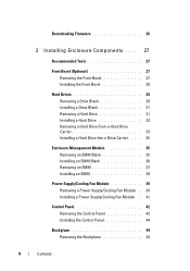
... Module 35 Removing an EMM Blank 35 Installing an EMM Blank 36 Removing an EMM 37 Installing an EMM 39 Power Supply/Cooling Fan Module 39 Removing a Power Supply/Cooling Fan Module . . 39 Installing a Power Supply/Cooling Fan Module . . 41 Control Panel 42 Removing the Control Panel 42 Installing the Control Panel 44 Backplane 44 Removing...
... Module 35 Removing an EMM Blank 35 Installing an EMM Blank 36 Removing an EMM 37 Installing an EMM 39 Power Supply/Cooling Fan Module 39 Removing a Power Supply/Cooling Fan Module . . 39 Installing a Power Supply/Cooling Fan Module . . 41 Control Panel 42 Removing the Control Panel 42 Installing the Control Panel 44 Backplane 44 Removing...

Hardware Owner's Manual
Page 5
... Enclosure 49 Safety First-For You and Your Enclosure 49 Troubleshooting Enclosure Startup Failure 49 Troubleshooting Loss of Communication 49 Troubleshooting External Connections 49 Troubleshooting Power Supply/Cooling Fan Module . . 50 Troubleshooting Enclosure Cooling Problems . . . . . 51 Troubleshooting Enclosure Management Modules. . . 52 Troubleshooting Hard Drives 53 Troubleshooting Enclosure Connections 54 Troubleshooting a Wet Enclosure...
... Enclosure 49 Safety First-For You and Your Enclosure 49 Troubleshooting Enclosure Startup Failure 49 Troubleshooting Loss of Communication 49 Troubleshooting External Connections 49 Troubleshooting Power Supply/Cooling Fan Module . . 50 Troubleshooting Enclosure Cooling Problems . . . . . 51 Troubleshooting Enclosure Management Modules. . . 52 Troubleshooting Hard Drives 53 Troubleshooting Enclosure Connections 54 Troubleshooting a Wet Enclosure...
Hardware Owner's Manual
Page 8
... lights when at least one power supply is pushed again. 8 About Your Enclosure When the button is pushed, the system status indicators on the front control panel can be used to the ... in the fault state. The system identification button on the control panel and the EMM blinks blue until the button is supplying power to locate a particular enclosure within a rack. Blinks amber when the enclosure is on or is pressed. Lights amber when the enclosure is turned on . Blinks ...
... lights when at least one power supply is pushed again. 8 About Your Enclosure When the button is pushed, the system status indicators on the front control panel can be used to the ... in the fault state. The system identification button on the control panel and the EMM blinks blue until the button is supplying power to locate a particular enclosure within a rack. Blinks amber when the enclosure is on or is pressed. Lights amber when the enclosure is turned on . Blinks ...

Hardware Owner's Manual
Page 10
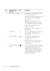
... enclosure is in a split-mode configuration. Lights blue during normal operation and when the host server is supplying power to the enclosure. The power LED lights when at least one power supply is identifying the enclosure. If the LED is not lit, it indicates that the enclosure is in a... the system identification button is in the fault state. Item Indicator, Button, or Icon Connector 1 Enclosure status LED 2 Power LED 3 Split mode LED Description The enclosure status LED lights when the enclosure power is reset. Lights amber when the enclosure is turned on or is on.
... enclosure is in a split-mode configuration. Lights blue during normal operation and when the host server is supplying power to the enclosure. The power LED lights when at least one power supply is identifying the enclosure. If the LED is not lit, it indicates that the enclosure is in a... the system identification button is in the fault state. Item Indicator, Button, or Icon Connector 1 Enclosure status LED 2 Power LED 3 Split mode LED Description The enclosure status LED lights when the enclosure power is reset. Lights amber when the enclosure is turned on or is on.

Hardware Owner's Manual
Page 12
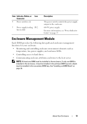
...functions for your enclosure. 12 About Your Enclosure For more information, see "Power Indicator Codes" on page 17. Back-Panel Features and Indicators 1 2 3 4 5 Item Indicator, Button, or Icon Connector 1 Power supply/cooling PS 1 fan module 2 Primary enclosure EMM 0 management module (...EMM) 3 Secondary EMM EMM 1 Description 600 W power supply. Drive-Status Indicator Pattern (RAID Only) Condition Blinks green, amber, and off...
...functions for your enclosure. 12 About Your Enclosure For more information, see "Power Indicator Codes" on page 17. Back-Panel Features and Indicators 1 2 3 4 5 Item Indicator, Button, or Icon Connector 1 Power supply/cooling PS 1 fan module 2 Primary enclosure EMM 0 management module (...EMM) 3 Secondary EMM EMM 1 Description 600 W power supply. Drive-Status Indicator Pattern (RAID Only) Condition Blinks green, amber, and off...
Hardware Owner's Manual
Page 13
...; Controlling access to hard drives. • Communicating enclosure attributes and states to the enclosure. 600 W power supply. About Your Enclosure 13 Item Indicator, Button, or Icon Connector 4 Power switches (2) 5 Power supply/cooling PS 2 fan module Description The power switch controls the power supply output to the host server. See "Installing an EMM Blank" on page 17. For more...
...; Controlling access to hard drives. • Communicating enclosure attributes and states to the enclosure. 600 W power supply. About Your Enclosure 13 Item Indicator, Button, or Icon Connector 4 Power switches (2) 5 Power supply/cooling PS 2 fan module Description The power switch controls the power supply output to the host server. See "Installing an EMM Blank" on page 17. For more...
Hardware Owner's Manual
Page 16
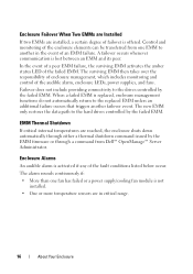
...transferred from Dell™ OpenManage™ Server Administrator. EMM Thermal Shutdown If critical internal temperatures are reached, the enclosure shuts down automatically through either a thermal shutdown command issued by the EMM firmware or through a command from one fan has failed or a power supply/cooling ...In the event of a peer EMM failure, the surviving EMM activates the amber status LED of the audible alarm, enclosure LEDs, power supplies, and fans. Enclosure Failover When Two EMMs are Installed If two EMMs are installed, a certain degree of failover is activated if...
...transferred from Dell™ OpenManage™ Server Administrator. EMM Thermal Shutdown If critical internal temperatures are reached, the enclosure shuts down automatically through either a thermal shutdown command issued by the EMM firmware or through a command from one fan has failed or a power supply/cooling ...In the event of a peer EMM failure, the surviving EMM activates the amber status LED of the audible alarm, enclosure LEDs, power supplies, and fans. Enclosure Failover When Two EMMs are Installed If two EMMs are installed, a certain degree of failover is activated if...
Hardware Owner's Manual
Page 17
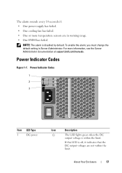
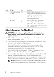
... voltages are in Server Administrator. Power Indicator Codes Figure 1-7. The alarm sounds every 10 seconds if: • One power supply has failed. • One cooling fan has failed. • One or more information, see the Server Administrator documentation at support.dell.com/manuals. NOTE: The alarm... is within the limit. About Your Enclosure 17 To enable the alarm, you must change the default setting in warning range. • One EMM has failed. Power Indicator Codes 1 2 3 Item LED Type 1 DC power Icon Description ...
... voltages are in Server Administrator. Power Indicator Codes Figure 1-7. The alarm sounds every 10 seconds if: • One power supply has failed. • One cooling fan has failed. • One or more information, see the Server Administrator documentation at support.dell.com/manuals. NOTE: The alarm... is within the limit. About Your Enclosure 17 To enable the alarm, you must change the default setting in warning range. • One EMM has failed. Power Indicator Codes 1 2 3 Item LED Type 1 DC power Icon Description ...
Hardware Owner's Manual
Page 18
... Server Administrator documentation provides information about managing your storage solution using the storage management service within the server administrator. • The Dell PowerEdge RAID Controller (PERC) H700 and H800 User's Guide provides information about configuring RAID. • Any media that ships with... and tools for updates on support.dell.com/manuals and read the updates first because they often supersede information in other documents. 18 About Your Enclosure Item LED Type Icon 2 Power supply/cooling fan fault 3 AC power Description The LED lights amber when ...
... Server Administrator documentation provides information about managing your storage solution using the storage management service within the server administrator. • The Dell PowerEdge RAID Controller (PERC) H700 and H800 User's Guide provides information about configuring RAID. • Any media that ships with... and tools for updates on support.dell.com/manuals and read the updates first because they often supersede information in other documents. 18 About Your Enclosure Item LED Type Icon 2 Power supply/cooling fan fault 3 AC power Description The LED lights amber when ...
Hardware Owner's Manual
Page 24
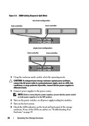
... the LEDs are amber, see "Troubleshooting Your Enclosure" on the front and back panel of the storage enclosure. NOTE: Before connecting the power supplies, ensure that the power switch on both power supplies is in Split Mode two-host configuration host controller host controller single-host configuration host controller host controller 4 Using the enclosure mode...
... the LEDs are amber, see "Troubleshooting Your Enclosure" on the front and back panel of the storage enclosure. NOTE: Before connecting the power supplies, ensure that the power switch on both power supplies is in Split Mode two-host configuration host controller host controller single-host configuration host controller host controller 4 Using the enclosure mode...

Hardware Owner's Manual
Page 25
...mode to unified mode-Some virtual disks may appear as necessary. 7 Turn on the enclosure by turning off the enclosure by turning on both power supply/cooling fan modules. 5 Change the position of the enclosure mode switch. 6 Rearrange the disks in the enclosure. NOTE: Split-mode configurations... do not support daisy-chaining of enclosures and redundant paths. 3 Turn off the host system. 4 Turn off both power supply/cooling fan modules. 8 Turn on the host system. 9 If required, recreate virtual disks in the enclosure as foreign if the configuration is not...
...mode to unified mode-Some virtual disks may appear as necessary. 7 Turn on the enclosure by turning off the enclosure by turning on both power supply/cooling fan modules. 5 Change the position of the enclosure mode switch. 6 Rearrange the disks in the enclosure. NOTE: Split-mode configurations... do not support daisy-chaining of enclosures and redundant paths. 3 Turn off the host system. 4 Turn off both power supply/cooling fan modules. 8 Turn on the host system. 9 If required, recreate virtual disks in the enclosure as foreign if the configuration is not...

Hardware Owner's Manual
Page 39
... instructions that is not authorized by a certified service technician. Power Supply/Cooling Fan Module Your enclosure supports two hot-swappable power supply/cooling fan modules. While the enclosure can be done by Dell is installed. 1 Turn off the power supply/cooling fan module. 2 Disconnect the power cable from a powered-on enclosure for the EMM. Installing an EMM CAUTION: Many...
... instructions that is not authorized by a certified service technician. Power Supply/Cooling Fan Module Your enclosure supports two hot-swappable power supply/cooling fan modules. While the enclosure can be done by Dell is installed. 1 Turn off the power supply/cooling fan module. 2 Disconnect the power cable from a powered-on enclosure for the EMM. Installing an EMM CAUTION: Many...
Hardware Owner's Manual
Page 40
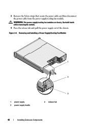
3 Remove the Velcro straps that secure the power cable and then disconnect the power cable from the power supply/cooling fan module. Removing and Installing a Power Supply/Cooling Fan Module OUT OUT 1 2 1 power supply 3 power supply handle 3 2 release tab 40 Installing Enclosure Components Figure 3-9. WARNING: The power supply/cooling fan modules are heavy. Use both hands while removing the module. 4 Press the release tab and pull the power supply out of the chassis.
3 Remove the Velcro straps that secure the power cable and then disconnect the power cable from the power supply/cooling fan module. Removing and Installing a Power Supply/Cooling Fan Module OUT OUT 1 2 1 power supply 3 power supply handle 3 2 release tab 40 Installing Enclosure Components Figure 3-9. WARNING: The power supply/cooling fan modules are heavy. Use both hands while removing the module. 4 Press the release tab and pull the power supply out of the chassis.
Hardware Owner's Manual
Page 41
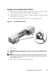
... cable with the Velcro strap. NOTE: If the enclosure is powered on the power supply/cooling fan module. Installing Enclosure Components 41 Installing a Power Supply/Cooling Fan Module 1 Slide the power supply/cooling fan module into the chassis until the AC power cable is connected to the power supply/cooling fan module and plug the cable into place. See Figure...
... cable with the Velcro strap. NOTE: If the enclosure is powered on the power supply/cooling fan module. Installing Enclosure Components 41 Installing a Power Supply/Cooling Fan Module 1 Slide the power supply/cooling fan module into the chassis until the AC power cable is connected to the power supply/cooling fan module and plug the cable into place. See Figure...

Hardware Owner's Manual
Page 44
...into place in your warranty. See Figure 3-12. 3 Replace the hard drives in PowerVault MD1200. Removing the Backplane 1 Turn off the enclosure and disconnect it from the electrical outlet. 2 Disconnect all the power cables to the chassis. 44 Installing Enclosure Components See Figure 3-11. - See "...technician. Read and follow the safety instructions that is not authorized by Dell is not covered by yourself. See "Removing the Control Panel" on page 42. 7 Remove the screws that secure the EMM/power supply cage to the enclosure. 5 Turn on the enclosure. 2 Slide ...
...into place in your warranty. See Figure 3-12. 3 Replace the hard drives in PowerVault MD1200. Removing the Backplane 1 Turn off the enclosure and disconnect it from the electrical outlet. 2 Disconnect all the power cables to the chassis. 44 Installing Enclosure Components See Figure 3-11. - See "...technician. Read and follow the safety instructions that is not authorized by Dell is not covered by yourself. See "Removing the Control Panel" on page 42. 7 Remove the screws that secure the EMM/power supply cage to the enclosure. 5 Turn on the enclosure. 2 Slide ...

Hardware Owner's Manual
Page 45
... the EMM/Power Supply Cage 2 1 EMM/power supply cage 1 2 screws (6) Installing Enclosure Components 45 See Figure 3-14 for PowerVault MD1200 or Figure 3-15 for PowerVault MD1220. 11 Remove the screws that secures the backplane to the chassis. See Figure 3-14 for PowerVault MD1200 or Figure 3-15 for PowerVault MD1220. 8... Grasp the cage removal ring at the bottom center of the enclosure and pull the EMM/power supply cage toward the back of the enclosure. See Figure ...
... the EMM/Power Supply Cage 2 1 EMM/power supply cage 1 2 screws (6) Installing Enclosure Components 45 See Figure 3-14 for PowerVault MD1200 or Figure 3-15 for PowerVault MD1220. 11 Remove the screws that secures the backplane to the chassis. See Figure 3-14 for PowerVault MD1200 or Figure 3-15 for PowerVault MD1220. 8... Grasp the cage removal ring at the bottom center of the enclosure and pull the EMM/power supply cage toward the back of the enclosure. See Figure ...


