
Glossary
Page 1
backup - A module that includes power supplies and fans. An information pathway between the processor and RAM. Common Information Model describes the management information utilized by an administrator, for security or tracking purposes. Dell™ Glossary NOTE: For additional information on...and a data bus for interchange of a program or data file. C - Advanced Configuration and Power Interface. An individual code assigned to direct configuration and power management. A CD, diskette, or USB memory key that is located. It provides mapping techniques for...
backup - A module that includes power supplies and fans. An information pathway between the processor and RAM. Common Information Model describes the management information utilized by an administrator, for security or tracking purposes. Dell™ Glossary NOTE: For additional information on...and a data bus for interchange of a program or data file. C - Advanced Configuration and Power Interface. An individual code assigned to direct configuration and power management. A CD, diskette, or USB memory key that is located. It provides mapping techniques for...

Glossary
Page 8
...as password protection. SNMP - Simple Network Management Protocol. system configuration information - termination - An unregistered (unbuffered) DDR3 memory module. A battery-powered unit that automatically supplies power to remotely monitor and manage workstations. USB - Used to describe a system that allows a network manager to your system's hardware and customize the... same set of your system's integral components, such as mice and keyboards. U-DIMM - Universal Serial Bus. Uninterruptible power supply. SMP - Symmetric multiprocessing. TCP/IP offload engine.
...as password protection. SNMP - Simple Network Management Protocol. system configuration information - termination - An unregistered (unbuffered) DDR3 memory module. A battery-powered unit that automatically supplies power to remotely monitor and manage workstations. USB - Used to describe a system that allows a network manager to your system's hardware and customize the... same set of your system's integral components, such as mice and keyboards. U-DIMM - Universal Serial Bus. Uninterruptible power supply. SMP - Symmetric multiprocessing. TCP/IP offload engine.

Glossary
Page 48
Simple Network Management Protocol SVGA - Watt-hour WMI - Symmetric multiprocessing I/O OS SNMP - Super video graphics array VGA と SVGA TCP/IP - Uninterruptible power supply USB - Volts alternating current VDC - Watt WH - Zero insertion force 48 Transmission Control Protocol/Internet Protocol TOE - Unregistered DDR3 UPS - Volt VAC - Video graphics array ...
Simple Network Management Protocol SVGA - Watt-hour WMI - Symmetric multiprocessing I/O OS SNMP - Super video graphics array VGA と SVGA TCP/IP - Uninterruptible power supply USB - Volts alternating current VDC - Watt WH - Zero insertion force 48 Transmission Control Protocol/Internet Protocol TOE - Unregistered DDR3 UPS - Volt VAC - Video graphics array ...

Glossary
Page 58
TCP/IP TCP/IP Offload Engine U-DIMM DDR3 Unregistered(Unbuffered) DDR3 Memory Module UPS Uninterruptible Power Supply USB Universal Serial Bus USB USB USB USB V - 볼트 (Volt VAC Volt Alternating Current VDC Volt Direct Current VGA Video Graphics Array VGA 와 ...; SVGA TCP/IP Transmission Control Protocol/Internet Protocol TOE - Windows Management Instrumentation 은 CIM ZIF Zero Insertion Force provider CIM management station managed system) 은 Dell OpenManage™ Server Administrator x x y x z 58
TCP/IP TCP/IP Offload Engine U-DIMM DDR3 Unregistered(Unbuffered) DDR3 Memory Module UPS Uninterruptible Power Supply USB Universal Serial Bus USB USB USB USB V - 볼트 (Volt VAC Volt Alternating Current VDC Volt Direct Current VGA Video Graphics Array VGA 와 ...; SVGA TCP/IP Transmission Control Protocol/Internet Protocol TOE - Windows Management Instrumentation 은 CIM ZIF Zero Insertion Force provider CIM management station managed system) 은 Dell OpenManage™ Server Administrator x x y x z 58

Getting Started Guide
Page 7
Turning On the System Press the power button on the system and the monitor. The power indicators should light. Getting Started With Your System 5 Plug the other end of the power cable into a loop as an uninterrupted power supply (UPS) or a power distribution unit (PDU). Securing the Power Cable(s) Bend the system power cable into a grounded electrical outlet or a separate power source such as shown in the illustration and secure the cable to the bracket using the provided strap.
Turning On the System Press the power button on the system and the monitor. The power indicators should light. Getting Started With Your System 5 Plug the other end of the power cable into a loop as an uninterrupted power supply (UPS) or a power distribution unit (PDU). Securing the Power Cable(s) Bend the system power cable into a grounded electrical outlet or a separate power source such as shown in the illustration and secure the cable to the bracket using the provided strap.
Getting Started Guide
Page 12
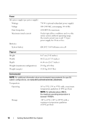
....0 kg (63.8 lbs) 15.85 kg (34.87 lbs) Environmental NOTE: For additional information about environmental measurements for 10 ms or less. Power AC power supply (per power supply) Wattage 750 W (optional redundant power supply) Voltage 100-240 VAC, autoranging, 50-60 Hz Heat dissipation 2450 BTU/hr maximum Maximum inrush current Under typical line conditions and...
....0 kg (63.8 lbs) 15.85 kg (34.87 lbs) Environmental NOTE: For additional information about environmental measurements for 10 ms or less. Power AC power supply (per power supply) Wattage 750 W (optional redundant power supply) Voltage 100-240 VAC, autoranging, 50-60 Hz Heat dissipation 2450 BTU/hr maximum Maximum inrush current Under typical line conditions and...

Setting Up Your Dell PowerVault NAS Solution
Page 1
...Dell PowerVault NX3100 storage system 4 2 5 3 6 Dell PowerVault MD12xx storage array (optional) 1. NOTE: The illustrations in this document are implemented on SAS HBA to expansion enclosure (optional) Power-Up Procedure You must consider any . Default Password The default password for lights-out management (optional) 3. iDRAC Enterprise port to the left of the power supplies... the terms of the agreement, please call 800-WWW-DELL (800-999-3355). After the storage arrays and enclosure(s) are found on the PowerVault NX3100 storage system. Using a Keyboard, Video, and Mouse Connect...
...Dell PowerVault NX3100 storage system 4 2 5 3 6 Dell PowerVault MD12xx storage array (optional) 1. NOTE: The illustrations in this document are implemented on SAS HBA to expansion enclosure (optional) Power-Up Procedure You must consider any . Default Password The default password for lights-out management (optional) 3. iDRAC Enterprise port to the left of the power supplies... the terms of the agreement, please call 800-WWW-DELL (800-999-3355). After the storage arrays and enclosure(s) are found on the PowerVault NX3100 storage system. Using a Keyboard, Video, and Mouse Connect...

Hardware Owner's Manual
Page 6
Replacing a Cooling Fan 79 Power Supplies 79 Removing a Redundant Power Supply 80 Installing a Redundant Power Supply 81 Removing the Power Supply Blank 82 Installing the Power Supply Blank 82 System Memory 82 General Memory Module Installation Guidelines 82 Mode-Specific Guidelines 84 Installing Memory Modules 87 Removing Memory Modules 89 Expansion Cards ...
Replacing a Cooling Fan 79 Power Supplies 79 Removing a Redundant Power Supply 80 Installing a Redundant Power Supply 81 Removing the Power Supply Blank 82 Installing the Power Supply Blank 82 System Memory 82 General Memory Module Installation Guidelines 82 Mode-Specific Guidelines 84 Installing Memory Modules 87 Removing Memory Modules 89 Expansion Cards ...

Hardware Owner's Manual
Page 8
... Troubleshooting a USB Device 130 Troubleshooting a Serial I/O Device 131 Troubleshooting a NIC 131 Troubleshooting a Wet System 132 Troubleshooting a Damaged System 134 Troubleshooting the System Battery 134 Troubleshooting Power Supplies 135 Troubleshooting System Cooling Problems 136 Troubleshooting a Fan 136 Troubleshooting System Memory 137 Troubleshooting an Internal USB Key 139 Troubleshooting a Hard Drive 140 Troubleshooting an...
... Troubleshooting a USB Device 130 Troubleshooting a Serial I/O Device 131 Troubleshooting a NIC 131 Troubleshooting a Wet System 132 Troubleshooting a Damaged System 134 Troubleshooting the System Battery 134 Troubleshooting Power Supplies 135 Troubleshooting System Cooling Problems 136 Troubleshooting a Fan 136 Troubleshooting System Memory 137 Troubleshooting an Internal USB Key 139 Troubleshooting a Hard Drive 140 Troubleshooting an...

Hardware Owner's Manual
Page 13
... on. When one of these buttons is pushed, the blue system status indicator on the back blinks until one of a paper clip. The power button controls the DC power supply output to locate a particular system within a rack. Used to troubleshoot software and device driver errors when using certain operating systems. This button can...
... on. When one of these buttons is pushed, the blue system status indicator on the back blinks until one of a paper clip. The power button controls the DC power supply output to locate a particular system within a rack. Used to troubleshoot software and device driver errors when using certain operating systems. This button can...
Hardware Owner's Manual
Page 18
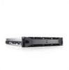
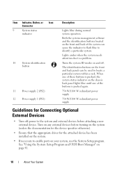
Item Indicator, Button, or Icon Connector 9 System status indicator 10 System identification button 11 Power supply 2 (PS2) 12 Power supply 1 (PS1) Description Lights blue during normal system operation. When one of these buttons is pushed, the system status indicator on ...driver for the attached device has been installed on the front and back of the buttons is pushed again. 750 W/1100 W redundant power supply 750 W/1100 W redundant power supply Guidelines for Connecting Optional External Devices • Turn off . Turn on your system, use the System Setup program. Lights amber when...
Item Indicator, Button, or Icon Connector 9 System status indicator 10 System identification button 11 Power supply 2 (PS2) 12 Power supply 1 (PS1) Description Lights blue during normal system operation. When one of these buttons is pushed, the system status indicator on ...driver for the attached device has been installed on the front and back of the buttons is pushed again. 750 W/1100 W redundant power supply 750 W/1100 W redundant power supply Guidelines for Connecting Optional External Devices • Turn off . Turn on your system, use the System Setup program. Lights amber when...
Hardware Owner's Manual
Page 19
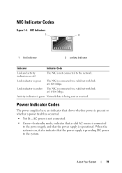
... connected to the network. Activity indicator is green Network data is connected to the system. When the system is on, it also indicates that the power supply is not connected to a valid network link at 1000 Mbps. NIC Indicators 1 2 1 link indicator 2 activity indicator Indicator Indicator Code Link and activity indicators are off...
... connected to the network. Activity indicator is green Network data is connected to the system. When the system is on, it also indicates that the power supply is not connected to a valid network link at 1000 Mbps. NIC Indicators 1 2 1 link indicator 2 activity indicator Indicator Indicator Code Link and activity indicators are off...
Hardware Owner's Manual
Page 20
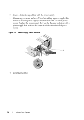
Power Supply Status Indicator 1 1 power supply status 20 About Your System Figure 1-5. • Amber-Indicates a problem with the other installed power supply. Replace the power supply that has the flashing indicator with a power supply that the power supply is mismatched with the power supply. • Alternating green and amber-When hot-adding a power supply, this indicates that matches the capacity of the other power supply.
Power Supply Status Indicator 1 1 power supply status 20 About Your System Figure 1-5. • Amber-Indicates a problem with the other installed power supply. Replace the power supply that has the flashing indicator with a power supply that the power supply is mismatched with the power supply. • Alternating green and amber-When hot-adding a power supply, this indicates that matches the capacity of the other power supply.
Hardware Owner's Manual
Page 25
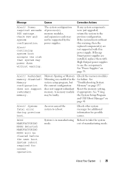
...Memory" on page 41. Check other system messages for additional information for failure. MANUFACTURING MODE will be supported by the power supplies. About Your System 25 If the system boots without warning. Memory configuration does not support redundant memory. The system ...Alert! Continuing system boot accepts the risk that system may be faulty. If Energy Smart power supplies are not supported with High Output power supplies to take the system mode. See "Power Supplies" on page 79. does not support redundant Reset the memory setting, memory. A memory ...
...Memory" on page 41. Check other system messages for additional information for failure. MANUFACTURING MODE will be supported by the power supplies. About Your System 25 If the system boots without warning. Memory configuration does not support redundant memory. The system ...Alert! Continuing system boot accepts the risk that system may be faulty. If Energy Smart power supplies are not supported with High Output power supplies to take the system mode. See "Power Supplies" on page 79. does not support redundant Reset the memory setting, memory. A memory ...

Hardware Owner's Manual
Page 38
..., then the replaced component(s) are installed in the system. You can obtain two power supplies of processor(s), memory modules, and expansion cards may not be supported by the power supplies. Warning! The recommended memory configuration is not optimal. See "Power Supplies" on one power supply until you can also run the system on page 79. PSU mismatch. See...
..., then the replaced component(s) are installed in the system. You can obtain two power supplies of processor(s), memory modules, and expansion cards may not be supported by the power supplies. Warning! The recommended memory configuration is not optimal. See "Power Supplies" on one power supply until you can also run the system on page 79. PSU mismatch. See...
Hardware Owner's Manual
Page 64
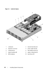
Figure 3-1. Inside the System 5 4 3 2 1 6 10 1 cooling fan 3 expansion-card riser 5 cooling shroud 7 memory modules (8) 9 SAS backplane 7 8 9 2 internal hard drives (2) 4 power supply bays (2) 6 heat sink/processor (2) 8 system cooling fans (4) 10 hard drives (12) 64 Installing System Components
Figure 3-1. Inside the System 5 4 3 2 1 6 10 1 cooling fan 3 expansion-card riser 5 cooling shroud 7 memory modules (8) 9 SAS backplane 7 8 9 2 internal hard drives (2) 4 power supply bays (2) 6 heat sink/processor (2) 8 system cooling fans (4) 10 hard drives (12) 64 Installing System Components
Hardware Owner's Manual
Page 77
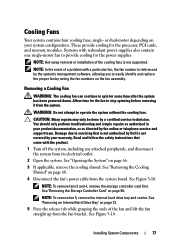
.... Allow time for some time after the system has been powered down. Read and follow the safety instructions that came with redundant power supplies also contain one single-motor fan to servicing that is not authorized by Dell is not supported. See "Removing the Cooling Shroud" on ...certified service technician. See Figure 3-10. NOTE: To remove fan 5, remove the internal hard drive bay and carrier. These provide cooling for the power supplies. See "Removing the Storage Controller Card" on page 66. 3 If applicable, remove the cooling shroud. Systems with the product. 1 Turn off...
.... Allow time for some time after the system has been powered down. Read and follow the safety instructions that came with redundant power supplies also contain one single-motor fan to servicing that is not authorized by Dell is not supported. See "Removing the Cooling Shroud" on ...certified service technician. See Figure 3-10. NOTE: To remove fan 5, remove the internal hard drive bay and carrier. These provide cooling for the power supplies. See "Removing the Storage Controller Card" on page 66. 3 If applicable, remove the cooling shroud. Systems with the product. 1 Turn off...
Hardware Owner's Manual
Page 79
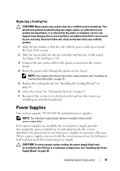
...CAUTION: To ensure proper system cooling, the power supply blank must be done by the online or...power load across both power supplies to servicing that the side with the system powered on the chassis. Installing System Components 79 Power Supplies Your system supports 750 W/1100 W redundant power supplies...not authorized by the remaining power supply. See "Installing the Power Supply Blank" on the power supply label. Replacing a Cooling ...two power supplies are installed, the second power supply provides hot-swappable, power redundancy. When a power supply is removed with the power cable...
...CAUTION: To ensure proper system cooling, the power supply blank must be done by the online or...power load across both power supplies to servicing that the side with the system powered on the chassis. Installing System Components 79 Power Supplies Your system supports 750 W/1100 W redundant power supplies...not authorized by the remaining power supply. See "Installing the Power Supply Blank" on the power supply label. Replacing a Cooling ...two power supplies are installed, the second power supply provides hot-swappable, power redundancy. When a power supply is removed with the power cable...

Hardware Owner's Manual
Page 80
... by Dell is not covered by the online or telephone service and support team. For information about the cable management arm, see the system's rack documentation. 3 Press the lever release latch and slide the power supply out of the chassis. NOTE: Install a power supply blank if you are not replacing the power supply. NOTE: If only one power supply...
... by Dell is not covered by the online or telephone service and support team. For information about the cable management arm, see the system's rack documentation. 3 Press the lever release latch and slide the power supply out of the chassis. NOTE: Install a power supply blank if you are not replacing the power supply. NOTE: If only one power supply...
Hardware Owner's Manual
Page 81
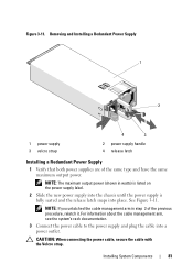
... and the release latch snaps into a power outlet. NOTE: The maximum output power (shown in step 2 of the same type and have the same maximum output power. Figure 3-11. Installing System Components 81 Removing and Installing a Redundant Power Supply 1 2 1 power supply 3 velcro strap 4 3 2 power supply handle 4 release latch Installing a Redundant Power Supply 1 Verify that both power supplies are of the previous procedure, relatch...
... and the release latch snaps into a power outlet. NOTE: The maximum output power (shown in step 2 of the same type and have the same maximum output power. Figure 3-11. Installing System Components 81 Removing and Installing a Redundant Power Supply 1 2 1 power supply 3 velcro strap 4 3 2 power supply handle 4 release latch Installing a Redundant Power Supply 1 Verify that both power supplies are of the previous procedure, relatch...


