Handling swollen Lithium-ion batteries
Page 1
...in recent years and have become standard in an approved shipping container (provided by Dell), to comply with your Dell computer. To discharge the battery, unplug the AC adapter from Dell. 1 Contact Dell product support at an approved recycling center. or its subsidiaries. One type of...: 2020-06-11 Previous Release Version: A04 Like most laptops, Dell laptops use a battery from Dell that is the lithium-ion polymer battery. Do not use lithium-ion batteries. A05 June 2020 Handling swollen Lithium-ion batteries Current Release Version: A05 Release Date: 2020-06-11 Previous Release...
...in recent years and have become standard in an approved shipping container (provided by Dell), to comply with your Dell computer. To discharge the battery, unplug the AC adapter from Dell. 1 Contact Dell product support at an approved recycling center. or its subsidiaries. One type of...: 2020-06-11 Previous Release Version: A04 Like most laptops, Dell laptops use a battery from Dell that is the lithium-ion polymer battery. Do not use lithium-ion batteries. A05 June 2020 Handling swollen Lithium-ion batteries Current Release Version: A05 Release Date: 2020-06-11 Previous Release...

Handling swollen Lithium-ion batteries
Page 2
For more information on how to improve the performance and lifespan of the laptop battery and to minimize the possibility of occurrence of charge cycles, or exposure to high heat. Frequently Asked Questions. 2 Lithium-ion batteries can swell for various reasons such as age, number of the issue, see Dell Laptop Battery -
For more information on how to improve the performance and lifespan of the laptop battery and to minimize the possibility of occurrence of charge cycles, or exposure to high heat. Frequently Asked Questions. 2 Lithium-ion batteries can swell for various reasons such as age, number of the issue, see Dell Laptop Battery -
Vostro 14-5468 Owners Manual
Page 3
... installing components...12 Recommended tools...12 Removing the back cover...12 Installing the back cover...13 Removing the battery...13 Installing the battery...14 Removing the battery cable...14 Installing the battery cable...15 Removing the memory module...15 Installing the memory module...16 Removing the solid state drive -...the hard drive bracket...21 Removing the WLAN card...21 Installing the WLAN card...22 Removing the coin cell battery...22 Installing the coin cell battery...23 Removing the Input-Output board...23 Installing the Input-Output board...24 Removing the fan...24 Installing ...
... installing components...12 Recommended tools...12 Removing the back cover...12 Installing the back cover...13 Removing the battery...13 Installing the battery...14 Removing the battery cable...14 Installing the battery cable...15 Removing the memory module...15 Installing the memory module...16 Removing the solid state drive -...the hard drive bracket...21 Removing the WLAN card...21 Installing the WLAN card...22 Removing the coin cell battery...22 Installing the coin cell battery...23 Removing the Input-Output board...23 Installing the Input-Output board...24 Removing the fan...24 Installing ...

Vostro 14-5468 Owners Manual
Page 5
... Specifications...61 Physical dimension specifications...61 System information specifications...61 Processor specifications...61 Memory specifications...61 Audio specifications...62 Video specifications...62 Communication specifications...62 Battery specifications...62 Ports and connector specifications...63 Display specifications...63 Touchpad specifications...64 Keyboard specifications...64 Adapter specifications...64 Environmental specifications...64 7 System setup options...
... Specifications...61 Physical dimension specifications...61 System information specifications...61 Processor specifications...61 Memory specifications...61 Audio specifications...62 Video specifications...62 Communication specifications...62 Battery specifications...62 Ports and connector specifications...63 Display specifications...63 Touchpad specifications...64 Keyboard specifications...64 Adapter specifications...64 Environmental specifications...64 7 System setup options...

Vostro 14-5468 Owners Manual
Page 6
ePSA diagnostics 75 LED error codes...75 Battery status lights...76 9 Contacting Dell...77 Contacting Dell...77 6 Contents POST Behavior screen options...72 Virtualization support screen options...73 Wireless screen options...73 Maintenance screen options...74 System Log screen options...74 8 Troubleshooting...75 Enhanced Pre-Boot System Assessment -
ePSA diagnostics 75 LED error codes...75 Battery status lights...76 9 Contacting Dell...77 Contacting Dell...77 6 Contents POST Behavior screen options...72 Virtualization support screen options...73 Wireless screen options...73 Maintenance screen options...74 System Log screen options...74 8 Troubleshooting...75 Enhanced Pre-Boot System Assessment -

Vostro 14-5468 Owners Manual
Page 8
... After you complete any replacement procedure, ensure you connect any telephone or network cables to your computer. Do not use only the battery designed for other Dell computers. 1 Connect any external devices, such as a port replicator or media base, and replace any cards, such as an ExpressCard...your computer CAUTION: To connect a network cable, first plug the cable into the network device and then plug it into the computer. 3 Replace the battery. 4 Replace the base cover. 5 Connect your computer. CAUTION: To avoid damage to their electrical outlets. 6 Turn on your computer. 8 Working...
... After you complete any replacement procedure, ensure you connect any telephone or network cables to your computer. Do not use only the battery designed for other Dell computers. 1 Connect any external devices, such as a port replicator or media base, and replace any cards, such as an ExpressCard...your computer CAUTION: To connect a network cable, first plug the cable into the network device and then plug it into the computer. 3 Replace the battery. 4 Replace the base cover. 5 Connect your computer. CAUTION: To avoid damage to their electrical outlets. 6 Turn on your computer. 8 Working...

Vostro 14-5468 Owners Manual
Page 9
Front view 2 Product overview 1 Digital-array microphone 3 Camera-status light 5 Display 2 Camera 4 Digital-array microphone 6 Power and battery status light/hard-drive activity light Product overview 9
Front view 2 Product overview 1 Digital-array microphone 3 Camera-status light 5 Display 2 Camera 4 Digital-array microphone 6 Power and battery status light/hard-drive activity light Product overview 9

Vostro 14-5468 Owners Manual
Page 13
... the computer. 3 Follow the procedure in After working inside your computer Removing the battery 1 Follow the procedure in Before working inside your computer. 2 Remove the back cover. 3 To remove the battery: a Disconnect the battery cable from all sides [1]. Removing and installing components 13 a Using a scribe, pry the edges of the back cover from... on the computer. 2 Tighten the screws to secure the base cover to the computer [2]. b Lift the back cover from the computer [3]. c Lift and remove the battery from the computer [2].
... the computer. 3 Follow the procedure in After working inside your computer Removing the battery 1 Follow the procedure in Before working inside your computer. 2 Remove the back cover. 3 To remove the battery: a Disconnect the battery cable from all sides [1]. Removing and installing components 13 a Using a scribe, pry the edges of the back cover from... on the computer. 2 Tighten the screws to secure the base cover to the computer [2]. b Lift the back cover from the computer [3]. c Lift and remove the battery from the computer [2].

Vostro 14-5468 Owners Manual
Page 14
Installing the battery 1 Insert the battery into the slot on the computer. 2 Install the screws that secure the battery to the computer. 3 Connect the battery cable to the connector on the system board. 4 Install the back cover. 5 Follow the procedure in After working inside your computer Removing the battery cable 1 Follow the procedure in Before working inside your computer. 2 Remove the: a back cover b battery 3 Disconnect the battery cable from its connector on the battery. 14 Removing and installing components
Installing the battery 1 Insert the battery into the slot on the computer. 2 Install the screws that secure the battery to the computer. 3 Connect the battery cable to the connector on the system board. 4 Install the back cover. 5 Follow the procedure in After working inside your computer Removing the battery cable 1 Follow the procedure in Before working inside your computer. 2 Remove the: a back cover b battery 3 Disconnect the battery cable from its connector on the battery. 14 Removing and installing components

Vostro 14-5468 Owners Manual
Page 15
Installing the battery cable 1 Connect the battery cable to the battery cable on the battery. 2 Install the: a battery b back cover 3 Follow the procedure in After working inside your computer Removing the memory module 1 Follow the procedure in Before working inside your computer. 2 Remove the: a back cover b battery 3 To remove the memory module: a Pull the retention clips from the connector on the system board. Removing and installing components 15 b Remove the memory module from the memory module until it pops up.
Installing the battery cable 1 Connect the battery cable to the battery cable on the battery. 2 Install the: a battery b back cover 3 Follow the procedure in After working inside your computer Removing the memory module 1 Follow the procedure in Before working inside your computer. 2 Remove the: a back cover b battery 3 To remove the memory module: a Pull the retention clips from the connector on the system board. Removing and installing components 15 b Remove the memory module from the memory module until it pops up.
Vostro 14-5468 Owners Manual
Page 16
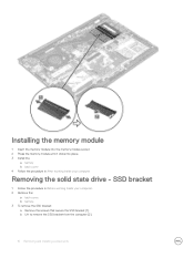
SSD bracket 1 Follow the procedure in After working inside your computer. 2 Remove the: a back cover. b Lift to remove the SSD bracket from the computer [2]. 16 Removing and installing components Installing the memory module 1 Insert the memory module into the memory module socket. 2 Press the memory module until it clicks into place. 3 Install the: a battery b back cover 4 Follow the procedure in Before working inside your computer Removing the solid state drive - b battery. 3 To remove the SSD bracket: a Remove the screws that secure the SSD bracket [1] .
SSD bracket 1 Follow the procedure in After working inside your computer. 2 Remove the: a back cover. b Lift to remove the SSD bracket from the computer [2]. 16 Removing and installing components Installing the memory module 1 Insert the memory module into the memory module socket. 2 Press the memory module until it clicks into place. 3 Install the: a battery b back cover 4 Follow the procedure in Before working inside your computer Removing the solid state drive - b battery. 3 To remove the SSD bracket: a Remove the screws that secure the SSD bracket [1] .

Vostro 14-5468 Owners Manual
Page 17
... computer. 2 Tighten the screws that secure the SSD to the computer [1] . SSD 1 Follow the procedure in After working inside your computer. 2 Remove the: a back cover. b battery. 3 To remove the hard drive: a Remove the screws that secure the SSD bracket . 3 Install the...
... computer. 2 Tighten the screws that secure the SSD to the computer [1] . SSD 1 Follow the procedure in After working inside your computer. 2 Remove the: a back cover. b battery. 3 To remove the hard drive: a Remove the screws that secure the SSD bracket . 3 Install the...

Vostro 14-5468 Owners Manual
Page 18
... computer Removing the hard drive 1 Follow the procedure in Before working inside your computer. 2 Remove the: a back cover b battery 3 To remove the hard drive: a Lift the tab to the computer. 3 Install the: a battery. b Remove the screws that secure the SSD to disconnect the hard drive cable from the computer [3]. 18 Removing and...
... computer Removing the hard drive 1 Follow the procedure in Before working inside your computer. 2 Remove the: a back cover b battery 3 To remove the hard drive: a Lift the tab to the computer. 3 Install the: a battery. b Remove the screws that secure the SSD to disconnect the hard drive cable from the computer [3]. 18 Removing and...
Vostro 14-5468 Owners Manual
Page 19
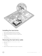
b back cover 5 Follow the procedure in After working inside your computer Removing the hard drive cable 1 Follow the procedure in Before working inside your computer. 2 Remove the: a back cover b battery c hard drive 3 Disconnect the hard drive cable from the connector on the system board. 4 Install the: a battery. Installing the hard drive 1 Insert the hard drive assembly into its slot on the computer. 2 Tighten the screws that secure the hard drive to the computer 3 Connect the hard drive cable to the connector on the hard drive. Removing and installing components 19
b back cover 5 Follow the procedure in After working inside your computer Removing the hard drive cable 1 Follow the procedure in Before working inside your computer. 2 Remove the: a back cover b battery c hard drive 3 Disconnect the hard drive cable from the connector on the system board. 4 Install the: a battery. Installing the hard drive 1 Insert the hard drive assembly into its slot on the computer. 2 Tighten the screws that secure the hard drive to the computer 3 Connect the hard drive cable to the connector on the hard drive. Removing and installing components 19
Vostro 14-5468 Owners Manual
Page 20
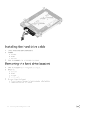
Installing the hard drive cable 1 Connect the hard drive cable to the hard drive. 2 Install the: a hard drive b battery c back cover 3 Follow the procedure in After working inside your computer Removing the hard drive bracket 1 Follow the procedure in Before working inside your computer. 2 Remove the: a back cover b battery c hard drive d hard-drive cable 3 To remove the hard-drive bracket: a Remove the screws that secure the hard-drive bracket to the hard drive. b Lift and remove the hard-drive bracket. 20 Removing and installing components
Installing the hard drive cable 1 Connect the hard drive cable to the hard drive. 2 Install the: a hard drive b battery c back cover 3 Follow the procedure in After working inside your computer Removing the hard drive bracket 1 Follow the procedure in Before working inside your computer. 2 Remove the: a back cover b battery c hard drive d hard-drive cable 3 To remove the hard-drive bracket: a Remove the screws that secure the hard-drive bracket to the hard drive. b Lift and remove the hard-drive bracket. 20 Removing and installing components
Vostro 14-5468 Owners Manual
Page 21
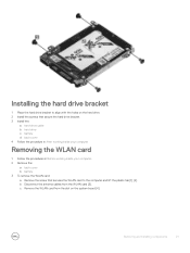
... antenna cables from the slot on the hard drive. 2 Install the screws that secure the hard drive bracket. 3 Install the: a hard-drive cable b hard drive c battery d back cover 4 Follow the procedure in After working inside your computer Removing the WLAN card 1 Follow the procedures in Before working inside your computer. 2 Remove...
... antenna cables from the slot on the hard drive. 2 Install the screws that secure the hard drive bracket. 3 Install the: a hard-drive cable b hard drive c battery d back cover 4 Follow the procedure in After working inside your computer Removing the WLAN card 1 Follow the procedures in Before working inside your computer. 2 Remove...

Vostro 14-5468 Owners Manual
Page 22
... cover. 6 Follow the procedure in After working inside your computer Removing the coin cell battery 1 Follow the procedure in Before working inside your computer. 2 Remove the: a back cover b battery 3 To remove the coin cell battery: a Pry the coin cell battery upwards from its slot using a scribe [1] . Installing the WLAN card 1 Insert the WLAN card.... 3 Tighten the screw to secure the WLAN card to the computer. 4 Connect the antenna cables to the connectors marked on the WLAN card. 5 Install the: a battery.
... cover. 6 Follow the procedure in After working inside your computer Removing the coin cell battery 1 Follow the procedure in Before working inside your computer. 2 Remove the: a back cover b battery 3 To remove the coin cell battery: a Pry the coin cell battery upwards from its slot using a scribe [1] . Installing the WLAN card 1 Insert the WLAN card.... 3 Tighten the screw to secure the WLAN card to the computer. 4 Connect the antenna cables to the connectors marked on the WLAN card. 5 Install the: a battery.

Vostro 14-5468 Owners Manual
Page 23
... procedure in After working inside your computer Removing the Input-Output board 1 Follow the procedure in Before working inside your computer. 2 Remove the: a back cover b battery c WLAN card 3 To remove the I/O board: a Disconnect the I/O board connector cable from the computer [4]. c Lift and remove the I /O board to the system board [3]. b Remove the...
... procedure in After working inside your computer Removing the Input-Output board 1 Follow the procedure in Before working inside your computer. 2 Remove the: a back cover b battery c WLAN card 3 To remove the I/O board: a Disconnect the I/O board connector cable from the computer [4]. c Lift and remove the I /O board to the system board [3]. b Remove the...
Vostro 14-5468 Owners Manual
Page 24
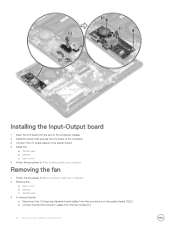
... the computer chassis. 2 Install the screw that secures the I/O board to the computer. 3 Connect the I/O board cables to the system board. 4 Install the: a WLAN card b battery c back cover 5 Follow the procedure in After working inside your computer Removing the fan 1 Follow the procedure in Before working inside your computer. 2 Remove the...
... the computer chassis. 2 Install the screw that secures the I/O board to the computer. 3 Connect the I/O board cables to the system board. 4 Install the: a WLAN card b battery c back cover 5 Follow the procedure in After working inside your computer Removing the fan 1 Follow the procedure in Before working inside your computer. 2 Remove the...

Vostro 14-5468 Owners Manual
Page 26
Installing the fan 1 Install the fan into the slot on the system board. 2 Tighten the screws to secure the fan module. 3 Connect the I/O board and system fan cable to the system board connectors. 4 Install the: a WLAN card b battery c back cover 5 Follow the procedure in After working inside your computer Removing the heatsink 1 Follow the procedure in Before working inside your computer. 2 Remove the: a back cover b battery c system fan 3 To remove the heatsink: a Remove the screws that secure the heatsink module to the computer chassis. 26 Removing and installing components
Installing the fan 1 Install the fan into the slot on the system board. 2 Tighten the screws to secure the fan module. 3 Connect the I/O board and system fan cable to the system board connectors. 4 Install the: a WLAN card b battery c back cover 5 Follow the procedure in After working inside your computer Removing the heatsink 1 Follow the procedure in Before working inside your computer. 2 Remove the: a back cover b battery c system fan 3 To remove the heatsink: a Remove the screws that secure the heatsink module to the computer chassis. 26 Removing and installing components


