Vostro 14-5468 Owners Manual
Page 3
...24 Removing the fan...24 Installing the fan...26 Removing the heatsink...26 Installing the heatsink...27 Removing the LED board...27 Contents 3 SSD bracket...16 Installing the solid state drive - Contents 1 Working on your computer...7 Safety instructions...7 Before working inside your computer...7 Turning ...tools...12 Removing the back cover...12 Installing the back cover...13 Removing the battery...13 Installing the battery...14 Removing the battery cable...14 Installing the battery cable...15 Removing the memory module...15 Installing the memory module...16 Removing the solid state drive...
...24 Removing the fan...24 Installing the fan...26 Removing the heatsink...26 Installing the heatsink...27 Removing the LED board...27 Contents 3 SSD bracket...16 Installing the solid state drive - Contents 1 Working on your computer...7 Safety instructions...7 Before working inside your computer...7 Turning ...tools...12 Removing the back cover...12 Installing the back cover...13 Removing the battery...13 Installing the battery...14 Removing the battery cable...14 Installing the battery cable...15 Removing the memory module...15 Installing the memory module...16 Removing the solid state drive...
Vostro 14-5468 Owners Manual
Page 16
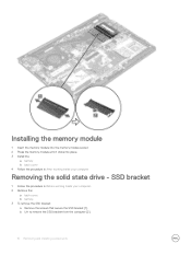
Installing the memory module 1 Insert the memory module into the memory module socket. 2 Press the memory module until it clicks into place. 3 Install the: a battery b back cover 4 Follow the procedure in Before working inside your computer Removing the solid state drive - SSD bracket 1 Follow the procedure in After working inside your computer. 2 Remove the: a back cover. b Lift to remove the SSD bracket from the computer [2]. 16 Removing and installing components b battery. 3 To remove the SSD bracket: a Remove the screws that secure the SSD bracket [1] .
Installing the memory module 1 Insert the memory module into the memory module socket. 2 Press the memory module until it clicks into place. 3 Install the: a battery b back cover 4 Follow the procedure in Before working inside your computer Removing the solid state drive - SSD bracket 1 Follow the procedure in After working inside your computer. 2 Remove the: a back cover. b Lift to remove the SSD bracket from the computer [2]. 16 Removing and installing components b battery. 3 To remove the SSD bracket: a Remove the screws that secure the SSD bracket [1] .

Vostro 14-5468 Owners Manual
Page 17
...cover. Removing and installing components 17 b Disconnect the SSD from its slot on the system board [2]. Installing the solid state drive - SSD bracket 1 Insert the SSD bracket into its connector on the computer. 2 Tighten the screws that secure the SSD to the computer [1] . b battery. 3 To ...remove the hard drive: a Remove the screws that secure the SSD bracket . 3 Install the: a ...
...cover. Removing and installing components 17 b Disconnect the SSD from its slot on the system board [2]. Installing the solid state drive - SSD bracket 1 Insert the SSD bracket into its connector on the computer. 2 Tighten the screws that secure the SSD to the computer [1] . b battery. 3 To ...remove the hard drive: a Remove the screws that secure the SSD bracket . 3 Install the: a ...

Vostro 14-5468 Owners Manual
Page 18
c Lift the hard drive from the connector on the computer. 2 Tighten the screws that secure the SSD to the computer. 3 Install the: a battery. b back cover. 4 Follow the procedure in After working inside your computer Removing the hard drive 1 Follow the procedure in ... screws that secure the hard drive to disconnect the hard drive cable from the computer [3]. 18 Removing and installing components Installing the Solid state drive - SSD 1 Insert the SSD into its slot on the system board [1] .
c Lift the hard drive from the connector on the computer. 2 Tighten the screws that secure the SSD to the computer. 3 Install the: a battery. b back cover. 4 Follow the procedure in After working inside your computer Removing the hard drive 1 Follow the procedure in ... screws that secure the hard drive to disconnect the hard drive cable from the computer [3]. 18 Removing and installing components Installing the Solid state drive - SSD 1 Insert the SSD into its slot on the system board [1] .

Vostro 14-5468 Owners Manual
Page 32
... procedure in After working inside your computer Removing the system board 1 Follow the procedure in Before working inside your computer. 2 Remove the: a back cover b battery c SSD bracket d SSD e WLAN card f system fan g heat sink h display assembly 3 Lift the tab [1,2,3,4,6] to disconnect the cables [5] from their connectors on the system board. 32 Removing...
... procedure in After working inside your computer Removing the system board 1 Follow the procedure in Before working inside your computer. 2 Remove the: a back cover b battery c SSD bracket d SSD e WLAN card f system fan g heat sink h display assembly 3 Lift the tab [1,2,3,4,6] to disconnect the cables [5] from their connectors on the system board. 32 Removing...

Vostro 14-5468 Owners Manual
Page 35
.... 4 Connect the following cables: a System board cable b Display power supply cable c Display connector cable 5 Install the: a display assembly b system fan c WLAN card d heat sink e SSD bracket f SSD g system fan h battery i back cover 6 Follow the procedure in After working inside your computer Removing the display assembly 1 Follow the procedure in Before working inside...
.... 4 Connect the following cables: a System board cable b Display power supply cable c Display connector cable 5 Install the: a display assembly b system fan c WLAN card d heat sink e SSD bracket f SSD g system fan h battery i back cover 6 Follow the procedure in After working inside your computer Removing the display assembly 1 Follow the procedure in Before working inside...
Vostro 14-5468 Owners Manual
Page 44
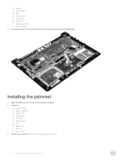
b battery c SSD bracket d SSD e WLAN card f system fan g heat sink h display assembly i system board 3 The palmrest can be removed after all other components have been disassembled. Installing the palmrest 1 Align the palmrest into its slot on the computer chassis. 2 Install the: a system board b display assembly c system fan d WLAN card e heat sink f SSD bracket g SSD h system fan i battery j back cover 3 Follow the procedure in After working inside your computer 44 Removing and installing components
b battery c SSD bracket d SSD e WLAN card f system fan g heat sink h display assembly i system board 3 The palmrest can be removed after all other components have been disassembled. Installing the palmrest 1 Align the palmrest into its slot on the computer chassis. 2 Install the: a system board b display assembly c system fan d WLAN card e heat sink f SSD bracket g SSD h system fan i battery j back cover 3 Follow the procedure in After working inside your computer 44 Removing and installing components
Vostro 14-5468 Owners Manual
Page 66
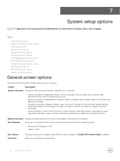
... Clock Speed, Minimum Clock Speed, Maximum Clock Speed, Processor L2 Cache, Processor L3 Cache, HT Capable, and 64-bit technology. • Device Information: SATA-0, M.2 PCIe SSD-0, Video Controller, Video BIOS Version, Video Memory, Panel Type, Native Resolution, Audio Controller, WiFi Device, WiGig Device, Cellular Device, Bluetooth Device. Boot Sequence Allows you...
... Clock Speed, Minimum Clock Speed, Maximum Clock Speed, Processor L2 Cache, Processor L3 Cache, HT Capable, and 64-bit technology. • Device Information: SATA-0, M.2 PCIe SSD-0, Video Controller, Video BIOS Version, Video Memory, Panel Type, Native Resolution, Audio Controller, WiFi Device, WiGig Device, Cellular Device, Bluetooth Device. Boot Sequence Allows you...
Vostro 14-5468 Owners Manual
Page 67
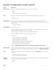
The options are: • SATA-1 • M.2 PCI-e SSD-0 SMART Reporting This field controls whether hard drive errors for OS. This technology is part of these settings. This field configures the integrated USB controller. ...) • Enable Thunderbolt Port (by default. The options are : • Disabled • AHCI • RAID On: This option is an optional feature. • Always Allows Dell Docks. The options are : • Enable Microphone (by default enabled) • Enable Internal Speaker (by default. • Enable SMART Reporting USB Configuration This is disabled...
The options are: • SATA-1 • M.2 PCI-e SSD-0 SMART Reporting This field controls whether hard drive errors for OS. This technology is part of these settings. This field configures the integrated USB controller. ...) • Enable Thunderbolt Port (by default. The options are : • Disabled • AHCI • RAID On: This option is an optional feature. • Always Allows Dell Docks. The options are : • Enable Microphone (by default enabled) • Enable Internal Speaker (by default. • Enable SMART Reporting USB Configuration This is disabled...
Vostro 14-5468 Owners Manual
Page 69
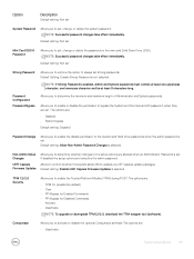
...NOTE: If Strong Password is set. The options are : • Deactivate System setup options 69 Default setting: Not set Mini Card SSD-0 Password Allows you to determine the minimum and maximum length of Administrator and System passwords. TPM 1.2/2.0 Security Allows you to set, change ...or delete the password on the mini card Solid State Drive (SSD). Non-Admin Setup Changes UEFI Capsule Firmware Updates Allows you to activate or disable the optional Computrace software The options are : •...
...NOTE: If Strong Password is set. The options are : • Deactivate System setup options 69 Default setting: Not set Mini Card SSD-0 Password Allows you to determine the minimum and maximum length of Administrator and System passwords. TPM 1.2/2.0 Security Allows you to set, change ...or delete the password on the mini card Solid State Drive (SSD). Non-Admin Setup Changes UEFI Capsule Firmware Updates Allows you to activate or disable the optional Computrace software The options are : •...


