
XPS 27 Service Manual
Page 4
Removing the memory modules 29 Prerequisites 29 Procedure 29 Replacing the memory modules 31 Procedure 31 Post-requisites 31 Removing the hard drive 32 Prerequisites 32 Procedure 32 Replacing the hard drive 35 Procedure 35 Post-requisites 35 Removing the system-board shield 36 Prerequisites 36 Procedure 36 Replacing the system-board shield 38 Procedure 38 Post-requisites 38 Removing the memory fan 39 Prerequisites 39 Procedure 39 Replacing the memory fan 41 Procedure 41 Post-requisites 41 4
Removing the memory modules 29 Prerequisites 29 Procedure 29 Replacing the memory modules 31 Procedure 31 Post-requisites 31 Removing the hard drive 32 Prerequisites 32 Procedure 32 Replacing the hard drive 35 Procedure 35 Post-requisites 35 Removing the system-board shield 36 Prerequisites 36 Procedure 36 Replacing the system-board shield 38 Procedure 38 Post-requisites 38 Removing the memory fan 39 Prerequisites 39 Procedure 39 Replacing the memory fan 41 Procedure 41 Post-requisites 41 4
XPS 27 Service Manual
Page 11
Removing the display panel 132 Prerequisites 132 Procedure 133 Replacing the display panel 134 Procedure 134 Post-requisites 137 BIOS setup program 139 BIOS overview 139 Entering the BIOS setup program 139 Clearing forgotten passwords 139 Prerequisites 140 Procedure 140 Post-requisites 141 Clearing CMOS settings 141 Prerequisites 141 Procedure 141 Post-requisites 142 Flashing the BIOS 143 System diagnostic lights 144 Getting help and contacting Dell 146 Self-help resources 146 Contacting Dell 146 11
Removing the display panel 132 Prerequisites 132 Procedure 133 Replacing the display panel 134 Procedure 134 Post-requisites 137 BIOS setup program 139 BIOS overview 139 Entering the BIOS setup program 139 Clearing forgotten passwords 139 Prerequisites 140 Procedure 140 Post-requisites 141 Clearing CMOS settings 141 Prerequisites 141 Procedure 141 Post-requisites 142 Flashing the BIOS 143 System diagnostic lights 144 Getting help and contacting Dell 146 Self-help resources 146 Contacting Dell 146 11

XPS 27 Service Manual
Page 12
... as keyboard, mouse, and monitor from your computer. 5 Remove any media card and optical disc from your computer, if applicable. 6 After the computer is unplugged, press and hold the power button for 5 seconds to protect your computer from potential damage and ensure your computer. - The shut-down . - Windows 10: Click Start → Power → Shut down instruction varies depending on the operating system installed on the configuration...
... as keyboard, mouse, and monitor from your computer. 5 Remove any media card and optical disc from your computer, if applicable. 6 After the computer is unplugged, press and hold the power button for 5 seconds to protect your computer from potential damage and ensure your computer. - The shut-down . - Windows 10: Click Start → Power → Shut down instruction varies depending on the operating system installed on the configuration...

XPS 27 Service Manual
Page 13
... any installed card from the media-card reader. When connecting cables, ensure that you finish working inside your computer, ground yourself by touching an unpainted metal surface, such as authorized or directed by the Dell technical assistance...connector pins. While you disconnect a cable, pull on its connector or on its pull tab, not on the cable itself. WARNING: Before working inside the computer, replace all power sources before connecting to dissipate static electricity, which could harm internal components. CAUTION: You should only perform troubleshooting and repairs...
... any installed card from the media-card reader. When connecting cables, ensure that you finish working inside your computer, ground yourself by touching an unpainted metal surface, such as authorized or directed by the Dell technical assistance...connector pins. While you disconnect a cable, pull on its connector or on its pull tab, not on the cable itself. WARNING: Before working inside the computer, replace all power sources before connecting to dissipate static electricity, which could harm internal components. CAUTION: You should only perform troubleshooting and repairs...

XPS 27 Service Manual
Page 14
Screw list Table 1. : Screw list Component Secured to Back-light cable System board Screw type M3X4 Quanti Screw image ty 1 Camera Middle frame M2X3 2 Chassis fan System board M2X3 4 Converter board Middle frame M3X4 3 Display Built-in Middle frame M2X3 2 Self Test button Hard-drive cage Middle frame M3X4 4 Hard-drive interposer I/O panel Hard-drive cage M2X3 4 Middle frame M3X4 4 I/O board I/O-board panel M3X4 1 Inner frame Middle frame M3X4 14 (touch screen) Inner frame (non-touch screen) Memory fan Middle frame M3X4 20 Middle frame M3X4 4 14
Screw list Table 1. : Screw list Component Secured to Back-light cable System board Screw type M3X4 Quanti Screw image ty 1 Camera Middle frame M2X3 2 Chassis fan System board M2X3 4 Converter board Middle frame M3X4 3 Display Built-in Middle frame M2X3 2 Self Test button Hard-drive cage Middle frame M3X4 4 Hard-drive interposer I/O panel Hard-drive cage M2X3 4 Middle frame M3X4 4 I/O board I/O-board panel M3X4 1 Inner frame Middle frame M3X4 14 (touch screen) Inner frame (non-touch screen) Memory fan Middle frame M3X4 20 Middle frame M3X4 4 14

XPS 27 Service Manual
Page 16
After working inside your computer CAUTION: Leaving stray or loose screws inside your computer may severely damage your computer. 1 Replace all screws and ensure that no stray screws remain inside your computer. 2 Connect any external devices, peripherals, or cables you removed before working on your computer. 3 Replace any media cards, discs, or any other parts that you removed before working on your computer. 4 Connect your computer and all attached devices to their electrical outlets. 5 Turn on your computer. 16
After working inside your computer CAUTION: Leaving stray or loose screws inside your computer may severely damage your computer. 1 Replace all screws and ensure that no stray screws remain inside your computer. 2 Connect any external devices, peripherals, or cables you removed before working on your computer. 3 Replace any media cards, discs, or any other parts that you removed before working on your computer. 4 Connect your computer and all attached devices to their electrical outlets. 5 Turn on your computer. 16

XPS 27 Service Manual
Page 19
Inside view of your computer (non-touch screen) Figure 2. : Inside view of your computer (non-touch screen) 1 2.5-inch hard drive 3 power-supply unit 5 microphone module 7 coin-cell battery 9 processor heat-sink 11 memory module 13 solid-state drive (M.2) 15 speakers (2) 17 I/O panel 19 USB dongle-port 2 hard-drive cage 4 chassis fan 6 system board 8 middle frame 10 processor 12 wireless-card shield 14 I/O board 16 memory fan 18 camera 20 display built-in self test button board 19
Inside view of your computer (non-touch screen) Figure 2. : Inside view of your computer (non-touch screen) 1 2.5-inch hard drive 3 power-supply unit 5 microphone module 7 coin-cell battery 9 processor heat-sink 11 memory module 13 solid-state drive (M.2) 15 speakers (2) 17 I/O panel 19 USB dongle-port 2 hard-drive cage 4 chassis fan 6 system board 8 middle frame 10 processor 12 wireless-card shield 14 I/O board 16 memory fan 18 camera 20 display built-in self test button board 19

XPS 27 Service Manual
Page 82
5 Lift the I/O panel off the middle frame. 6 Remove USB-dongle port. 7 Remove the Diagnostic light button board. 82
5 Lift the I/O panel off the middle frame. 6 Remove USB-dongle port. 7 Remove the Diagnostic light button board. 82

XPS 27 Service Manual
Page 83
... cover. 5 Replace the USB dongle-bay cover. 83 Procedure 1 Replace the Diagnostic light button board. 2 Replace USB-dongle port. 3 Connect the USB-dongle cable to the system board. 4 Align the screw holes on the middle frame. 5 Replace the four screws (M3X4) that secure the I /O-board panel with your computer and follow the instructions in Before working inside your computer. After working inside your computer, follow the steps in After working inside your computer. Replacing the I/O panel WARNING: Before working inside...
... cover. 5 Replace the USB dongle-bay cover. 83 Procedure 1 Replace the Diagnostic light button board. 2 Replace USB-dongle port. 3 Connect the USB-dongle cable to the system board. 4 Align the screw holes on the middle frame. 5 Replace the four screws (M3X4) that secure the I /O-board panel with your computer and follow the instructions in Before working inside your computer. After working inside your computer, follow the steps in After working inside your computer. Replacing the I/O panel WARNING: Before working inside...

XPS 27 Service Manual
Page 93
... the hard drive cables. 3 Disconnect the hard-drive power cable from the system board. 93 For more safety best practices, see the Regulatory Compliance home page at www.dell.com/ regulatory_compliance. After working inside your computer, follow the steps in After working inside your computer. Prerequisites 1 Remove the USB dongle-bay cover. 2 Remove the back cover. 3 Remove the stand. 4 Remove the hard drive. 5 Remove the system-board shield. 6 Remove the I/O panel. Removing the hard-drive cage WARNING: Before working inside your...
... the hard drive cables. 3 Disconnect the hard-drive power cable from the system board. 93 For more safety best practices, see the Regulatory Compliance home page at www.dell.com/ regulatory_compliance. After working inside your computer, follow the steps in After working inside your computer. Prerequisites 1 Remove the USB dongle-bay cover. 2 Remove the back cover. 3 Remove the stand. 4 Remove the hard drive. 5 Remove the system-board shield. 6 Remove the I/O panel. Removing the hard-drive cage WARNING: Before working inside your...
XPS 27 Service Manual
Page 113
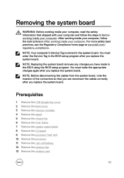
You must make the appropriate changes again after you replace the system board. Prerequisites 1 Remove the USB dongle-bay cover. 2 Remove the back cover. 3 Remove the memory modules. 4 Remove the stand. 5 Remove the chassis fan. 6 Remove the inner frame. 7 Remove the system-board shield. 8 Remove the I/O panel. 9 Remove the processor heat-sink. 10 Remove the processor. 11 Remove the coin-cell battery. 12 Remove the memory fan. 13 Remove the wireless card. 113 After working inside your computer, follow the steps in the BIOS setup program...
You must make the appropriate changes again after you replace the system board. Prerequisites 1 Remove the USB dongle-bay cover. 2 Remove the back cover. 3 Remove the memory modules. 4 Remove the stand. 5 Remove the chassis fan. 6 Remove the inner frame. 7 Remove the system-board shield. 8 Remove the I/O panel. 9 Remove the processor heat-sink. 10 Remove the processor. 11 Remove the coin-cell battery. 12 Remove the memory fan. 13 Remove the wireless card. 113 After working inside your computer, follow the steps in the BIOS setup program...
XPS 27 Service Manual
Page 117
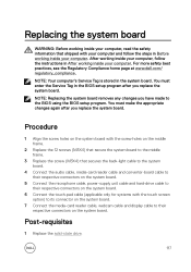
... 7 Connect the media-card reader cable, webcam cable and display cable to the BIOS using the BIOS setup program. Replacing the system board WARNING: Before working inside your computer, read the safety information that secures the back-light cable to the system board. 4 Connect the audio cable, media-card reader cable and converter-board cable to their respective connectors on the system board. 5 Connect the microphone cable, power-supply unit cable and hard-drive cable to their respective connectors on the system board. You must enter the Service Tag in After working inside your...
... 7 Connect the media-card reader cable, webcam cable and display cable to the BIOS using the BIOS setup program. Replacing the system board WARNING: Before working inside your computer, read the safety information that secures the back-light cable to the system board. 4 Connect the audio cable, media-card reader cable and converter-board cable to their respective connectors on the system board. 5 Connect the microphone cable, power-supply unit cable and hard-drive cable to their respective connectors on the system board. You must enter the Service Tag in After working inside your...

XPS 27 Service Manual
Page 121
... working inside your computer. Replacing the display assembly WARNING: Before working inside your computer, read the safety information that shipped with your computer and follow the instructions in self test button board. 2 Replace the system board. 3 Replace the camera. 4 Replace the media-card reader. 5 Replace the power-button board. 6 Replace the speakers. 7 Replace the converter board. 8 Replace the solid-state drive. 9 Replace the coin-cell battery. 10 Replace the hard-drive cage. 11 Replace the processor. 12 Replace the processor heat-sink. 13 Replace the I/O panel. 14 Replace...
... working inside your computer. Replacing the display assembly WARNING: Before working inside your computer, read the safety information that shipped with your computer and follow the instructions in self test button board. 2 Replace the system board. 3 Replace the camera. 4 Replace the media-card reader. 5 Replace the power-button board. 6 Replace the speakers. 7 Replace the converter board. 8 Replace the solid-state drive. 9 Replace the coin-cell battery. 10 Replace the hard-drive cage. 11 Replace the processor. 12 Replace the processor heat-sink. 13 Replace the I/O panel. 14 Replace...

XPS 27 Service Manual
Page 126
... frame. 6 Connect the backlight cable to its slot on the middle frame. 7 Connect the converter-board cable to its slot on the middle frame with your computer and follow the instructions in self test button board. 2 Replace the system board. 3 Replace the camera. 4 Replace the media-card reader. 5 Replace the power-button board. 6 Replace the speakers. 7 Replace the converter board. 8 Replace the solid-state drive. 9 Replace the coin-cell battery. 126 Post-requisites 1 Replace the display built-in After working inside your computer. Replacing the...
... frame. 6 Connect the backlight cable to its slot on the middle frame. 7 Connect the converter-board cable to its slot on the middle frame with your computer and follow the instructions in self test button board. 2 Replace the system board. 3 Replace the camera. 4 Replace the media-card reader. 5 Replace the power-button board. 6 Replace the speakers. 7 Replace the converter board. 8 Replace the solid-state drive. 9 Replace the coin-cell battery. 126 Post-requisites 1 Replace the display built-in After working inside your computer. Replacing the...
XPS 27 Service Manual
Page 139
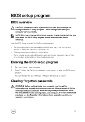
BIOS setup program BIOS overview CAUTION: Unless you change BIOS Setup program, it is displayed on or restart your computer, such as the user password, type of hard drive installed, and enabling or disabling base devices. Certain changes can change a user-selectable option, such as the amount of RAM and the size of the hard drive. • Change the system configuration information. • Set or change the user-definable settings in After working inside your computer. Clearing forgotten passwords WARNING: Before working inside your computer, read...
BIOS setup program BIOS overview CAUTION: Unless you change BIOS Setup program, it is displayed on or restart your computer, such as the user password, type of hard drive installed, and enabling or disabling base devices. Certain changes can change a user-selectable option, such as the amount of RAM and the size of the hard drive. • Change the system configuration information. • Set or change the user-definable settings in After working inside your computer. Clearing forgotten passwords WARNING: Before working inside your computer, read...

XPS 27 Service Manual
Page 144
... that the power supply is normal but another device in the computer is turned off . System diagnostic lights Light pattern Problem description 2,1 System board error 2,2 System board or power supply unit or power supply cable error 2,3 System board or memory or CPU error 2,4 Coin-cell battery error 2,5 BIOS failure 2,6 CPU failure 2,7 Memory or RAM failure 3,3 Memory error 3,5 Memory error 3,6 BIOS Recovery Image Not Found 3,7 BIOS Recovery Image Found But Invalid 144 The power status light blinks amber along with beep codes indicating failures. The following...
... that the power supply is normal but another device in the computer is turned off . System diagnostic lights Light pattern Problem description 2,1 System board error 2,2 System board or power supply unit or power supply cable error 2,3 System board or memory or CPU error 2,4 Coin-cell battery error 2,5 BIOS failure 2,6 CPU failure 2,7 Memory or RAM failure 3,3 Memory error 3,5 Memory error 3,6 BIOS Recovery Image Not Found 3,7 BIOS Recovery Image Found But Invalid 144 The power status light blinks amber along with beep codes indicating failures. The following...

XPS 27 Service Manual
Page 145
The computer may emit a series of beeps during start-up if the errors or problems cannot be displayed. Camera is in use. • Solid white - The repetitive beep codes help the user troubleshoot problems with the computer. Camera status light: Indicates whether the camera is in use . • Off - Camera is not in use . 145
The computer may emit a series of beeps during start-up if the errors or problems cannot be displayed. Camera is in use. • Solid white - The repetitive beep codes help the user troubleshoot problems with the computer. Camera status light: Indicates whether the camera is in use . • Off - Camera is not in use . 145
XPS 27 Setup and Specifications
Page 14
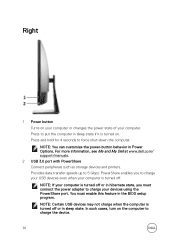
... computer in sleep state. NOTE: If your devices using the PowerShare port. Right 1 Power button Turns on your computer or changes the power state of your computer is turned off. Press and hold for 4 seconds to 5 Gbps. For more information, see Me and My Dell at www.dell.com/ support/manuals. 2 USB 3.0 port with PowerShare Connect peripherals such as storage devices and printers. You must connect the power adapter to charge...
... computer in sleep state. NOTE: If your devices using the PowerShare port. Right 1 Power button Turns on your computer or changes the power state of your computer is turned off. Press and hold for 4 seconds to 5 Gbps. For more information, see Me and My Dell at www.dell.com/ support/manuals. 2 USB 3.0 port with PowerShare Connect peripherals such as storage devices and printers. You must connect the power adapter to charge...

XPS 27 Setup and Specifications
Page 15
... rates up to 10 Gbps for USB 3.1 Gen 2 and up to 40 Gbps for Thunderbolt 3. 2 Network port Connect an Ethernet (RJ45) cable from a router or a broadband modem for network or internet access. 3 Power-supply diagnostics button Press to an external display using a display adapter. Back 1 Thunderbolt 3 (USB Type-C) ports (2) Supports USB 3.1 Gen 2, DisplayPort 1.2, Thunderbolt 3 and also enables you to connect to check the power‑supply state. 4 Power-supply diagnostics light Indicates the power-supply state. 5 DisplayPort Connect an external display or a projector. 6 USB 3.0 ports (4) 15
... rates up to 10 Gbps for USB 3.1 Gen 2 and up to 40 Gbps for Thunderbolt 3. 2 Network port Connect an Ethernet (RJ45) cable from a router or a broadband modem for network or internet access. 3 Power-supply diagnostics button Press to an external display using a display adapter. Back 1 Thunderbolt 3 (USB Type-C) ports (2) Supports USB 3.1 Gen 2, DisplayPort 1.2, Thunderbolt 3 and also enables you to connect to check the power‑supply state. 4 Power-supply diagnostics light Indicates the power-supply state. 5 DisplayPort Connect an external display or a projector. 6 USB 3.0 ports (4) 15
XPS 27 Setup and Specifications
Page 19
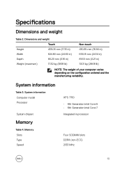
Memory Slots Type Speed XPS 7760 • 6th Generation Intel Core i5 • 6th Generation Intel Core i7 Integrated in ) 13.01 kg (28.68 lb) NOTE: The weight of your computer varies depending on the configuration ordered and the manufacturing variability. System information Computer model Processor System chipset Memory Table 4. Dimensions and weight Height Width Depth ...38.18 lb) Non-touch 430.35 mm (16.94 in) 613.05 mm (24.14 in) 81.60 mm (3.21 in processor Four SODIMM slots DDR4 (non-ECC) 2133 MHz 19 System information Table 3. Specifications Dimensions and weight Table 2.
Memory Slots Type Speed XPS 7760 • 6th Generation Intel Core i5 • 6th Generation Intel Core i7 Integrated in ) 13.01 kg (28.68 lb) NOTE: The weight of your computer varies depending on the configuration ordered and the manufacturing variability. System information Computer model Processor System chipset Memory Table 4. Dimensions and weight Height Width Depth ...38.18 lb) Non-touch 430.35 mm (16.94 in) 613.05 mm (24.14 in) 81.60 mm (3.21 in processor Four SODIMM slots DDR4 (non-ECC) 2133 MHz 19 System information Table 3. Specifications Dimensions and weight Table 2.


