

Owner's Manual (PDF)
Page 4
... Procedure 31 11 Replacing the System-Board Shield 33 Procedure 33 Postrequisites 33 12 Removing the Power-Supply Unit 35 Prerequisites 35 Procedure 35 13 Replacing the Power-Supply Unit 37 Procedure 37 Postrequisites 37 14 Removing the Memory Module(s 39 Prerequisites 39 Procedure 39 15 Replacing the Memory Module(s 41 Procedure 41 Postrequisites 41 16 Removing the Coin-Cell Battery 43 Prerequisites 43...
... Procedure 31 11 Replacing the System-Board Shield 33 Procedure 33 Postrequisites 33 12 Removing the Power-Supply Unit 35 Prerequisites 35 Procedure 35 13 Replacing the Power-Supply Unit 37 Procedure 37 Postrequisites 37 14 Removing the Memory Module(s 39 Prerequisites 39 Procedure 39 15 Replacing the Memory Module(s 41 Procedure 41 Postrequisites 41 16 Removing the Coin-Cell Battery 43 Prerequisites 43...
Owner's Manual (PDF)
Page 8
... 114 Entering the Service Tag in system setup 114 52 Removing the Speakers 115 Prerequisites 115 Procedure 115 53 Replacing the Speakers 117 Procedure 117 Postrequisites 117 54 Removing the Power-Button Assembly . . . . 119 Prerequisites 119 Procedure 119 55 Replacing the Power-Button Assembly . . . . 121 Procedure 121 Postrequisites 121 56 Removing the Side I/O-Board 123 Prerequisites 123 Procedure 124 57 Replacing the Side-I/O Board 125...
... 114 Entering the Service Tag in system setup 114 52 Removing the Speakers 115 Prerequisites 115 Procedure 115 53 Replacing the Speakers 117 Procedure 117 Postrequisites 117 54 Removing the Power-Button Assembly . . . . 119 Prerequisites 119 Procedure 119 55 Replacing the Power-Button Assembly . . . . 121 Procedure 121 Postrequisites 121 56 Removing the Side I/O-Board 123 Prerequisites 123 Procedure 124 57 Replacing the Side-I/O Board 125...
Owner's Manual (PDF)
Page 9
60 Removing the Display Panel 133 Prerequisites 133 Procedure 133 61 Replacing the Display Panel 139 Procedure 139 Postrequisites 140 62 Removing the Camera Module 141 Prerequisites 141 Procedure 142 63 Replacing the Camera Module 143 Procedure 143 Postrequisites 143 64 Removing the Microphone Modules 145 Prerequisites 145 Procedure 146 65 Replacing the Microphone Modules 147 Procedure 147 Postrequisites 147 66 Removing the Infrared (IR) Module 149 Prerequisites 149 Procedure 150...
60 Removing the Display Panel 133 Prerequisites 133 Procedure 133 61 Replacing the Display Panel 139 Procedure 139 Postrequisites 140 62 Removing the Camera Module 141 Prerequisites 141 Procedure 142 63 Replacing the Camera Module 143 Procedure 143 Postrequisites 143 64 Removing the Microphone Modules 145 Prerequisites 145 Procedure 146 65 Replacing the Microphone Modules 147 Procedure 147 Postrequisites 147 66 Removing the Infrared (IR) Module 149 Prerequisites 149 Procedure 150...
Owner's Manual (PDF)
Page 12
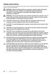
..., replace all power sources before connecting to the power source. After you must disengage before disconnecting the cable. CAUTION: When you work surface is authorized to remove the computer cover and access any connector pins. CAUTION: To disconnect a network cable, first unplug the cable from your computer and then unplug the cable from potential damage and ensure your personal safety. CAUTION: Only a certified service...
..., replace all power sources before connecting to the power source. After you must disengage before disconnecting the cable. CAUTION: When you work surface is authorized to remove the computer cover and access any connector pins. CAUTION: To disconnect a network cable, first unplug the cable from your computer and then unplug the cable from potential damage and ensure your personal safety. CAUTION: Only a certified service...
Owner's Manual (PDF)
Page 13
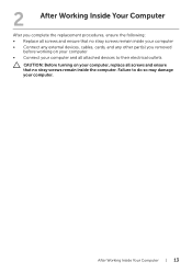
... their electrical outlets CAUTION: Before turning on your computer, replace all screws and ensure that no stray screws remain inside your computer • Connect any external devices, cables, cards, and any other part(s) you removed before working on your computer • Connect your computer and all attached devices to do so may damage your computer. 2 After Working Inside Your Computer After you complete...
... their electrical outlets CAUTION: Before turning on your computer, replace all screws and ensure that no stray screws remain inside your computer • Connect any external devices, cables, cards, and any other part(s) you removed before working on your computer • Connect your computer and all attached devices to do so may damage your computer. 2 After Working Inside Your Computer After you complete...
Owner's Manual (PDF)
Page 15
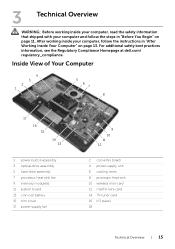
... "After Working Inside Your Computer" on page 11. Inside View of Your Computer 4 3 2 1 5 6 7 8 17 16 15 14 13 1 power-button assembly 3 optical-drive assembly 5 hard-drive assembly 7 processor heat-sink fan 9 memory module(s) 11 system board 13 coin-cell battery 15 trim cover 17 power-supply fan 9 10 11 12 2 converter board 4 power-supply unit 6 cooling vents 8 processor heat-sink 10 wireless mini-card 12 mSATA mini-card 14...
... "After Working Inside Your Computer" on page 11. Inside View of Your Computer 4 3 2 1 5 6 7 8 17 16 15 14 13 1 power-button assembly 3 optical-drive assembly 5 hard-drive assembly 7 processor heat-sink fan 9 memory module(s) 11 system board 13 coin-cell battery 15 trim cover 17 power-supply fan 9 10 11 12 2 converter board 4 power-supply unit 6 cooling vents 8 processor heat-sink 10 wireless mini-card 12 mSATA mini-card 14...
Owner's Manual (PDF)
Page 40
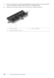
3 Use your fingertips to carefully spread apart the securing clips on each end of the memory-module connector until the memory module pops up. 4 Remove the memory module from the memory-module connector. 3 1 2 1 securing-clips (2) 3 memory-module connector 2 memory module 40 | Removing the Memory Module(s)
3 Use your fingertips to carefully spread apart the securing clips on each end of the memory-module connector until the memory module pops up. 4 Remove the memory module from the memory-module connector. 3 1 2 1 securing-clips (2) 3 memory-module connector 2 memory module 40 | Removing the Memory Module(s)

Owner's Manual (PDF)
Page 41
... a 45-degree angle and press the memory module down until it . 2 3 1 1 tab 3 memory module 2 memory-module connector 3 Slide the memory-module shield on page 11. See "Replacing the Back Cover" on the memory-module connector. 2 Slide the memory module firmly into place. After working inside your computer and follow the instructions in "Before You Begin" on the system-board shield and replace the screw that shipped with the...
... a 45-degree angle and press the memory module down until it . 2 3 1 1 tab 3 memory module 2 memory-module connector 3 Slide the memory-module shield on page 11. See "Replacing the Back Cover" on the memory-module connector. 2 Slide the memory module firmly into place. After working inside your computer and follow the instructions in "Before You Begin" on the system-board shield and replace the screw that shipped with the...

Owner's Manual (PDF)
Page 43
.... CAUTION: Removing the coin-cell battery resets the BIOS settings to the manufacturer's instructions. Prerequisites 1 Remove the back cover. For additional safety best practices information, see the Regulatory Compliance Homepage at dell.com/ regulatory_compliance. See "Removing the System-Board Shield" on page 19. 2 Remove the system-board shield. See "Removing the Back Cover" on page 31. Discard used batteries according to default. WARNING: The battery may explode if installed incorrectly...
.... CAUTION: Removing the coin-cell battery resets the BIOS settings to the manufacturer's instructions. Prerequisites 1 Remove the back cover. For additional safety best practices information, see the Regulatory Compliance Homepage at dell.com/ regulatory_compliance. See "Removing the System-Board Shield" on page 19. 2 Remove the system-board shield. See "Removing the Back Cover" on page 31. Discard used batteries according to default. WARNING: The battery may explode if installed incorrectly...
Owner's Manual (PDF)
Page 111
... Compliance Homepage at dell.com/ regulatory_compliance. See "Removing the Trim Cover" on page 91. 5 Remove the system-board shield. NOTE: Your computer's Service Tag is stored in "After Working Inside Your Computer" on page 13. See "Removing the mSATA Mini-Card" on page 39. 9 Remove the TV-tuner mini-card. Removing the System Board | 111 See "Removing the Memory Module(s)" on page 71. 11 Remove the wireless mini-card.
... Compliance Homepage at dell.com/ regulatory_compliance. See "Removing the Trim Cover" on page 91. 5 Remove the system-board shield. NOTE: Your computer's Service Tag is stored in "After Working Inside Your Computer" on page 13. See "Removing the mSATA Mini-Card" on page 39. 9 Remove the TV-tuner mini-card. Removing the System Board | 111 See "Removing the Memory Module(s)" on page 71. 11 Remove the wireless mini-card.

Owner's Manual (PDF)
Page 112
... cables from the system board: • Speaker cable • Power-button cable • Converter cable • Volume/Display-settings control cable • Hard-drive data cable • Hard-drive power cable • Optical-drive data cable • Optical-drive power cable • Main and processor power-supply cables • LVDS cable • Touchscreen cable • Processor heat-sink fan cable • Display-power cable • Camera cable • Infrared-receiver cable NOTE: For information on the location of the connectors, see "System-Board Components" on page 16. 2 Remove...
... cables from the system board: • Speaker cable • Power-button cable • Converter cable • Volume/Display-settings control cable • Hard-drive data cable • Hard-drive power cable • Optical-drive data cable • Optical-drive power cable • Main and processor power-supply cables • LVDS cable • Touchscreen cable • Processor heat-sink fan cable • Display-power cable • Camera cable • Infrared-receiver cable NOTE: For information on the location of the connectors, see "System-Board Components" on page 16. 2 Remove...
Owner's Manual (PDF)
Page 113
...; Power-button cable • Converter cable • Volume/Display-settings control cable • Hard-drive power cable • Hard-drive data cable • Optical-drive power cable • Optical-drive data cable • Main and processor power-supply cables • LVDS cable • Touchscreen cable • Processor heat-sink fan cable • Display-power cable • Camera cable • Infrared-receiver cable Replacing the System Board | 113 After working inside your computer and follow the instructions in "Before You Begin" on page 11. You must enter the Service Tag...
...; Power-button cable • Converter cable • Volume/Display-settings control cable • Hard-drive power cable • Hard-drive data cable • Optical-drive power cable • Optical-drive data cable • Main and processor power-supply cables • LVDS cable • Touchscreen cable • Processor heat-sink fan cable • Display-power cable • Camera cable • Infrared-receiver cable Replacing the System Board | 113 After working inside your computer and follow the instructions in "Before You Begin" on page 11. You must enter the Service Tag...
Owner's Manual (PDF)
Page 114
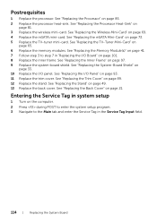
.... See "Replacing the Trim Cover" on page 85. 2 Replace the processor heat-sink. See "Replacing the Processor Heat-Sink" on page 33. 10 Replace the I /O Panel" on page 65. 6 Replace the memory modules. See "Replacing the System-Board Shield" on page 81. 3 Replace the wireless mini-card. Entering the Service Tag in system setup 1 Turn on page 69. 4 Replace the mSATA mini-card. Postrequisites 1 Replace the processor. See "Replacing the Wireless Mini-Card" on...
.... See "Replacing the Trim Cover" on page 85. 2 Replace the processor heat-sink. See "Replacing the Processor Heat-Sink" on page 33. 10 Replace the I /O Panel" on page 65. 6 Replace the memory modules. See "Replacing the System-Board Shield" on page 81. 3 Replace the wireless mini-card. Entering the Service Tag in system setup 1 Turn on page 69. 4 Replace the mSATA mini-card. Postrequisites 1 Replace the processor. See "Replacing the Wireless Mini-Card" on...
Owner's Manual (PDF)
Page 150
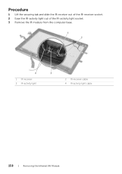
Procedure 1 Lift the securing tab and slide the IR receiver out of the IR-receiver socket. 2 Ease the IR-activity light out of the IR-activity light socket. 3 Remove the IR module from the computer base. 1 2 4 1 IR receiver 3 IR-activity light 3 2 IR-receiver cable 4 IR-activity light cable 150 | Removing the Infrared (IR) Module
Procedure 1 Lift the securing tab and slide the IR receiver out of the IR-receiver socket. 2 Ease the IR-activity light out of the IR-activity light socket. 3 Remove the IR module from the computer base. 1 2 4 1 IR receiver 3 IR-activity light 3 2 IR-receiver cable 4 IR-activity light cable 150 | Removing the Infrared (IR) Module
Owner's Manual (PDF)
Page 157
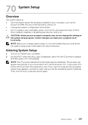
... amount of RAM, the size of the hard drive, and so on • Change the system configuration information • Set or change a user-selectable option, such as the user password, type of hard drive installed, enabling or disabling base devices, and so on (or restart) your computer. 2 During POST, when the DELL logo is displayed, watch for it is lost. Then, turn off your computer work incorrectly. 70 System Setup Overview Use system setup to...
... amount of RAM, the size of the hard drive, and so on • Change the system configuration information • Set or change a user-selectable option, such as the user password, type of hard drive installed, enabling or disabling base devices, and so on (or restart) your computer. 2 During POST, when the DELL logo is displayed, watch for it is lost. Then, turn off your computer work incorrectly. 70 System Setup Overview Use system setup to...
Owner's Manual (PDF)
Page 158
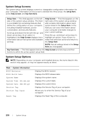
... make changes to enter the Service Tag of your computer and installed devices, the items listed in the Setup Item are changeable. Displays the current date. Displays the Service Tag of the computer. 158 | System Setup Help Screen - In this section may appear, or may not appear exactly as listed. System Setup Options NOTE: Depending on the screen is divided into three areas: the setup item, active help screen, and key functions...
... make changes to enter the Service Tag of your computer and installed devices, the items listed in the Setup Item are changeable. Displays the current date. Displays the Service Tag of the computer. 158 | System Setup Help Screen - In this section may appear, or may not appear exactly as listed. System Setup Options NOTE: Depending on the screen is divided into three areas: the setup item, active help screen, and key functions...

Owner's Manual (PDF)
Page 160
... enable or disable the onboard LAN controller. Side USB Ports Allows you to use turbo boost when required. Advanced → Onboard Device Configuration Onboard Audio Controller Allows you to enable or disable the onboard audio controller. Limit CPUID Value If enabled, limits the maximum value the processor CPUID function will allow your computer. Boot Numlock Key Select power-on state for numlock. Keyboard Errors Displays keyboard related errors during boot. CPU XD Support If enabled, will support. Advanced → USB Configuration Rear USB Ports...
... enable or disable the onboard LAN controller. Side USB Ports Allows you to use turbo boost when required. Advanced → Onboard Device Configuration Onboard Audio Controller Allows you to enable or disable the onboard audio controller. Limit CPUID Value If enabled, limits the maximum value the processor CPUID function will allow your computer. Boot Numlock Key Select power-on state for numlock. Keyboard Errors Displays keyboard related errors during boot. CPU XD Support If enabled, will support. Advanced → USB Configuration Rear USB Ports...

Owner's Manual (PDF)
Page 161
... restored. Power Wake Up by Integrated LAN/WLAN AC Recovery DeepSx Power Policies USB PowerShare in S4/S5 State USB PowerShare in S4/S5 state. Allows you to set a supervisor password. Allows you to enter the BIOS setup during POST. Displays the status of the supervisor password. You cannot use the user password to configure the DeepSx mode. System Setup | 161 Allows you to load the default BIOS settings. Allows you to change the user password...
... restored. Power Wake Up by Integrated LAN/WLAN AC Recovery DeepSx Power Policies USB PowerShare in S4/S5 State USB PowerShare in S4/S5 state. Allows you to set a supervisor password. Allows you to enter the BIOS setup during POST. Displays the status of the supervisor password. You cannot use the user password to configure the DeepSx mode. System Setup | 161 Allows you to load the default BIOS settings. Allows you to change the user password...

Owner's Manual (PDF)
Page 162
... Dell Diagnostics from the Drivers and Utilities disc. Changing Boot Sequence Changing Boot Sequence for the Current Boot You can use this feature to change the boot priority of the device. 162 | System Setup The Boot Device Menu appears, listing all available boot devices. 4 On the Boot Device Menu choose the device you see the operating system's desktop. Changing Boot Sequence for Future Boots 1 Enter system setup. The previous boot sequence is restored at the next boot. 1 If you are booting to a USB memory key, highlight USB Storage Device...
... Dell Diagnostics from the Drivers and Utilities disc. Changing Boot Sequence Changing Boot Sequence for the Current Boot You can use this feature to change the boot priority of the device. 162 | System Setup The Boot Device Menu appears, listing all available boot devices. 4 On the Boot Device Menu choose the device you see the operating system's desktop. Changing Boot Sequence for Future Boots 1 Enter system setup. The previous boot sequence is restored at the next boot. 1 If you are booting to a USB memory key, highlight USB Storage Device...
Owner's Manual (PDF)
Page 165
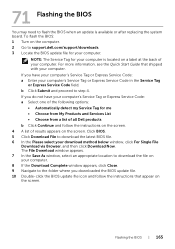
... Express Service Code: a Enter your download method below window, click For Single File Download via Browser, and then click Download Now. Flashing the BIOS | 165 Click BIOS. 5 Click Download File to support.dell.com/support/downloads. 3 Locate the BIOS update file for your computer. 71 Flashing the BIOS You may need to step 4. If you downloaded the BIOS update file. 10 Double-click the BIOS update file icon and follow the instructions on the screen. 4 A list of all Dell products...
... Express Service Code: a Enter your download method below window, click For Single File Download via Browser, and then click Download Now. Flashing the BIOS | 165 Click BIOS. 5 Click Download File to support.dell.com/support/downloads. 3 Locate the BIOS update file for your computer. 71 Flashing the BIOS You may need to step 4. If you downloaded the BIOS update file. 10 Double-click the BIOS update file icon and follow the instructions on the screen. 4 A list of all Dell products...


