

Owner's Manual (PDF)
Page 4
...-Supply Unit 35 Prerequisites 35 Procedure 35 13 Replacing the Power-Supply Unit 37 Procedure 37 Postrequisites 37 14 Removing the Memory Module(s 39 Prerequisites 39 Procedure 39 15 Replacing the Memory Module(s 41 Procedure 41 Postrequisites 41 16 Removing the Coin-Cell Battery 43 Prerequisites 43 Procedure 43 17 Replacing the...
...-Supply Unit 35 Prerequisites 35 Procedure 35 13 Replacing the Power-Supply Unit 37 Procedure 37 Postrequisites 37 14 Removing the Memory Module(s 39 Prerequisites 39 Procedure 39 15 Replacing the Memory Module(s 41 Procedure 41 Postrequisites 41 16 Removing the Coin-Cell Battery 43 Prerequisites 43 Procedure 43 17 Replacing the...
Owner's Manual (PDF)
Page 15
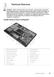
...the instructions in "Before You Begin" on page 13. For additional safety best practices information, see the Regulatory Compliance Homepage at dell.com/ regulatory_compliance. 3 Technical Overview WARNING: Before working inside your computer, read the safety information that shipped with your computer, follow...2 1 5 6 7 8 17 16 15 14 13 1 power-button assembly 3 optical-drive assembly 5 hard-drive assembly 7 processor heat-sink fan 9 memory module(s) 11 system board 13 coin-cell battery 15 trim cover 17 power-supply fan 9 10 11 12 2 converter board 4 power-supply unit 6 cooling vents...
...the instructions in "Before You Begin" on page 13. For additional safety best practices information, see the Regulatory Compliance Homepage at dell.com/ regulatory_compliance. 3 Technical Overview WARNING: Before working inside your computer, read the safety information that shipped with your computer, follow...2 1 5 6 7 8 17 16 15 14 13 1 power-button assembly 3 optical-drive assembly 5 hard-drive assembly 7 processor heat-sink fan 9 memory module(s) 11 system board 13 coin-cell battery 15 trim cover 17 power-supply fan 9 10 11 12 2 converter board 4 power-supply unit 6 cooling vents...

Owner's Manual (PDF)
Page 39
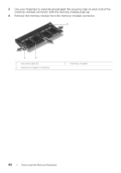
... follow the instructions in "Before You Begin" on page 11. For additional safety best practices information, see the Regulatory Compliance Homepage at dell.com/ regulatory_compliance. See "Removing the Back Cover" on page 13. After working inside your computer, follow the steps in "After Working... Inside Your Computer" on page 19. 14 Removing the Memory Module(s) WARNING: Before working inside your computer, read the safety information that secures the memory-module shield to the system-board shield. 2 Slide the memory-module shield toward the bottom of the computer to remove it...
... follow the instructions in "Before You Begin" on page 11. For additional safety best practices information, see the Regulatory Compliance Homepage at dell.com/ regulatory_compliance. See "Removing the Back Cover" on page 13. After working inside your computer, follow the steps in "After Working... Inside Your Computer" on page 19. 14 Removing the Memory Module(s) WARNING: Before working inside your computer, read the safety information that secures the memory-module shield to the system-board shield. 2 Slide the memory-module shield toward the bottom of the computer to remove it...
Owner's Manual (PDF)
Page 40
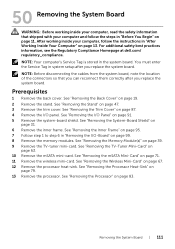
3 Use your fingertips to carefully spread apart the securing clips on each end of the memory-module connector until the memory module pops up. 4 Remove the memory module from the memory-module connector. 3 1 2 1 securing-clips (2) 3 memory-module connector 2 memory module 40 | Removing the Memory Module(s)
3 Use your fingertips to carefully spread apart the securing clips on each end of the memory-module connector until the memory module pops up. 4 Remove the memory module from the memory-module connector. 3 1 2 1 securing-clips (2) 3 memory-module connector 2 memory module 40 | Removing the Memory Module(s)

Owner's Manual (PDF)
Page 41
If you do not hear the click, remove the memory module and reinstall it clicks into the connector at dell.com/ regulatory_compliance. Replacing the Memory Module(s) | 41 Procedure 1 Align the notch on the memory module with your computer, follow the steps in "After Working Inside Your Computer" on page 11. See "Replacing the Back Cover...
If you do not hear the click, remove the memory module and reinstall it clicks into the connector at dell.com/ regulatory_compliance. Replacing the Memory Module(s) | 41 Procedure 1 Align the notch on the memory module with your computer, follow the steps in "After Working Inside Your Computer" on page 11. See "Replacing the Back Cover...

Owner's Manual (PDF)
Page 42
42 | Replacing the Memory Module(s)
42 | Replacing the Memory Module(s)
Owner's Manual (PDF)
Page 111
... panel. See "Removing the Processor Heat-Sink" on page 83. For additional safety best practices information, see the Regulatory Compliance Homepage at dell.com/ regulatory_compliance. NOTE: Before disconnecting the cables from the system board, note the location of the connectors so that shipped with your computer ...and follow the instructions in "After Working Inside Your Computer" on page 99. 8 Remove the memory modules. See "Removing the Trim Cover" on page 87. 4 Remove the I /O Panel" on page 91. 5 Remove the system-board shield...
... panel. See "Removing the Processor Heat-Sink" on page 83. For additional safety best practices information, see the Regulatory Compliance Homepage at dell.com/ regulatory_compliance. NOTE: Before disconnecting the cables from the system board, note the location of the connectors so that shipped with your computer ...and follow the instructions in "After Working Inside Your Computer" on page 99. 8 Remove the memory modules. See "Removing the Trim Cover" on page 87. 4 Remove the I /O Panel" on page 91. 5 Remove the system-board shield...
Owner's Manual (PDF)
Page 114
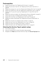
... Input field. 114 | Replacing the System Board Postrequisites 1 Replace the processor. See "Replacing the I /O Board" on page 101. 8 Replace the inner frame. See "Replacing the Memory Module(s)" on page 97. 9 Replace the system-board shield. See "Replacing the Wireless Mini-Card" on page 65. 6 Replace the... memory modules. See "Replacing the TV-Tuner Mini-Card" on page 69. 4 Replace the mSATA mini-card. See "Replacing the Inner Frame" on page 41. 7 Follow ...
... Input field. 114 | Replacing the System Board Postrequisites 1 Replace the processor. See "Replacing the I /O Board" on page 101. 8 Replace the inner frame. See "Replacing the Memory Module(s)" on page 97. 9 Replace the system-board shield. See "Replacing the Wireless Mini-Card" on page 65. 6 Replace the... memory modules. See "Replacing the TV-Tuner Mini-Card" on page 69. 4 Replace the mSATA mini-card. See "Replacing the Inner Frame" on page 41. 7 Follow ...
Owner's Manual (PDF)
Page 159
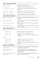
... on your computer. Displays the processor's total L1 cache size. Displays the device identification code. Displays the size of memory (RAM) technology used in your computer. Displays the type of the SATA device present in your computer. Displays the ...Information Processor Type Processor ID Processor Core Count Processor L1 Cache Processor L2 Cache Processor L3 Cache Main → Memory Information Memory Installed Memory Available Memory Running Speed Memory Technology Main → SATA Information SATA 1 Device Type Device ID Device Size SATA 2 Device Type Device ID...
... on your computer. Displays the processor's total L1 cache size. Displays the device identification code. Displays the size of memory (RAM) technology used in your computer. Displays the type of the SATA device present in your computer. Displays the ...Information Processor Type Processor ID Processor Core Count Processor L1 Cache Processor L2 Cache Processor L3 Cache Main → Memory Information Memory Installed Memory Available Memory Running Speed Memory Technology Main → SATA Information SATA 1 Device Type Device ID Device Size SATA 2 Device Type Device ID...

Owner's Manual (PDF)
Page 162
... through the list of devices. 4 Press plus (+) or minus (-) to change the current boot sequence, for example, to boot from the optical drive to run Dell Diagnostics from . See "Entering System Setup" on (or restart) your current boot sequence in the lower-right corner of the screen, press . Changing Boot Sequence... access the menu. The Boot Device Menu appears, listing all available boot devices. 4 On the Boot Device Menu choose the device you want to a USB memory key, highlight USB Storage Device and press .
... through the list of devices. 4 Press plus (+) or minus (-) to change the current boot sequence, for example, to boot from the optical drive to run Dell Diagnostics from . See "Entering System Setup" on (or restart) your current boot sequence in the lower-right corner of the screen, press . Changing Boot Sequence... access the menu. The Boot Device Menu appears, listing all available boot devices. 4 On the Boot Device Menu choose the device you want to a USB memory key, highlight USB Storage Device and press .


