

Literature/Product Sheet
Page 2
... 5 Sets Digital (Optical) Input .......... DENON ELECTRONICS DIVISION OF DENON CORPORATION (USA) 19 CHAPIN ROAD, P.O. s Digital-to instead drive 2 powered speakers in Singapore Sources can assign the 2 Surround Back amplifier channels to -Analog Recording The AVR-4802 lets you more accurately match the performance ...Dolby Labs, Inc., and is also automatically turned off , and with large LCD touch panel The AVR-4802's RC-8000 remote controller lets you control not only the AVR-4802 but also other gear such as "MODE CINEMA". *Design and specifications are power amp stage values...
... 5 Sets Digital (Optical) Input .......... DENON ELECTRONICS DIVISION OF DENON CORPORATION (USA) 19 CHAPIN ROAD, P.O. s Digital-to instead drive 2 powered speakers in Singapore Sources can assign the 2 Surround Back amplifier channels to -Analog Recording The AVR-4802 lets you more accurately match the performance ...Dolby Labs, Inc., and is also automatically turned off , and with large LCD touch panel The AVR-4802's RC-8000 remote controller lets you control not only the AVR-4802 but also other gear such as "MODE CINEMA". *Design and specifications are power amp stage values...

Owners Manual
Page 4
...possible from the tuner or TV. • Set the antenna wires from the tuner or TV away from the actual set for choosing the DENON AVR-4802 Digital Surround A / V receiver. As this product is used near a tuner or TV. If this happens, take the following steps: ...between all connections are proper and that there are included in addition to the main unit: w Warranty ( for North America model only 1 e Service station list 1 t Remote control unit y LR6/AA alkaline batteries...4 u AM loop antenna......1 (RC-8000 1 r AC cord 1 i FM indoor antenna......1 r t y u i 1 BEFORE USING...
...possible from the tuner or TV. • Set the antenna wires from the tuner or TV away from the actual set for choosing the DENON AVR-4802 Digital Surround A / V receiver. As this product is used near a tuner or TV. If this happens, take the following steps: ...between all connections are proper and that there are included in addition to the main unit: w Warranty ( for North America model only 1 e Service station list 1 t Remote control unit y LR6/AA alkaline batteries...4 u AM loop antenna......1 (RC-8000 1 r AC cord 1 i FM indoor antenna......1 r t y u i 1 BEFORE USING...

Owners Manual
Page 6
...out jacks Use these outlets is connected, disconnect the ground wire. Never connect equipment whose total capacity is supplied from the remote control unit. OUTPUT INPUT OPTICAL MD recorder, DAT deck or other component equipped with digital output jacks Connecting the DIGITAL jacks ...-B L SB / MULTI L AC OUTLETS POWER AMP OUT OUT IN ROOM TO ROOM REMOTE CONTROL R EXT. Use a separate head amplifier or step-up transformer. Do not use Ground wire Connecting a turntable Connect the turntable's output cord to the AVR-4802's PHONO jacks, the L (left) plug to the L jack, the R (right)...
...out jacks Use these outlets is connected, disconnect the ground wire. Never connect equipment whose total capacity is supplied from the remote control unit. OUTPUT INPUT OPTICAL MD recorder, DAT deck or other component equipped with digital output jacks Connecting the DIGITAL jacks ...-B L SB / MULTI L AC OUTLETS POWER AMP OUT OUT IN ROOM TO ROOM REMOTE CONTROL R EXT. Use a separate head amplifier or step-up transformer. Do not use Ground wire Connecting a turntable Connect the turntable's output cord to the AVR-4802's PHONO jacks, the L (left) plug to the L jack, the R (right)...
Owners Manual
Page 8
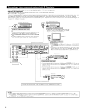
... the components' audio inputs and outputs as the REC/MULTI input function. 8 S-VIDEO IN OUT Video deck 2 POWER AMP OUT OUT IN ROOM TO ROOM REMOTE CONTROL Connecting the video decks • Connect the video deck's S output jack (S-OUT) to the S-VIDEO VCR-1 IN jack and the video deck's S input jack (S-IN...
... the components' audio inputs and outputs as the REC/MULTI input function. 8 S-VIDEO IN OUT Video deck 2 POWER AMP OUT OUT IN ROOM TO ROOM REMOTE CONTROL Connecting the video decks • Connect the video deck's S output jack (S-OUT) to the S-VIDEO VCR-1 IN jack and the video deck's S input jack (S-IN...
Owners Manual
Page 10
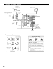
... C DVD VDP TV SL SURROUND -B R SB / MULTI R SBR ANTENNA SIGNAL PHONO GND L SBL I CD DVD VDP TV POWER AMP OUT OUT IN ROOM TO ROOM REMOTE CONTROL R EXT. Connection of the panel. 10 cord. 3.
... C DVD VDP TV SL SURROUND -B R SB / MULTI R SBR ANTENNA SIGNAL PHONO GND L SBL I CD DVD VDP TV POWER AMP OUT OUT IN ROOM TO ROOM REMOTE CONTROL R EXT. Connection of the panel. 10 cord. 3.
Owners Manual
Page 11
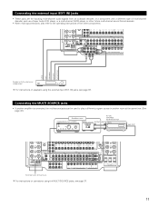
... page 37. 11 Connecting the external input (EXT. AUX VCR-1 AUDIO VCR-2 VCR-3 VCR-1 OUT VCR-2 VCR-3 POWER AMP OUT OUT IN ROOM TO ROOM REMOTE CONTROL R EXT. AUX VCR-1 VCR-2 VCR-3 VCR-1 VCR-2 VCR-3 AUDIO VCR-2 VCR-3 VCR-1 OUT VCR-2 VCR-3 1-MONITOR-2 IN CDR/ TAPE VIDEO OUT PRE OUT CDR/ MULTI... FRONT, CENTER, SB / MULTI 6~16Ω SURROUND A OR B 6~16Ω A + B 8~16Ω -A L SURROUND -B L SB / MULTI L AC OUTLETS POWER AMP OUT OUT IN ROOM TO ROOM REMOTE CONTROL R EXT.
... page 37. 11 Connecting the external input (EXT. AUX VCR-1 AUDIO VCR-2 VCR-3 VCR-1 OUT VCR-2 VCR-3 POWER AMP OUT OUT IN ROOM TO ROOM REMOTE CONTROL R EXT. AUX VCR-1 VCR-2 VCR-3 VCR-1 VCR-2 VCR-3 AUDIO VCR-2 VCR-3 VCR-1 OUT VCR-2 VCR-3 1-MONITOR-2 IN CDR/ TAPE VIDEO OUT PRE OUT CDR/ MULTI... FRONT, CENTER, SB / MULTI 6~16Ω SURROUND A OR B 6~16Ω A + B 8~16Ω -A L SURROUND -B L SB / MULTI L AC OUTLETS POWER AMP OUT OUT IN ROOM TO ROOM REMOTE CONTROL R EXT.
Owners Manual
Page 13
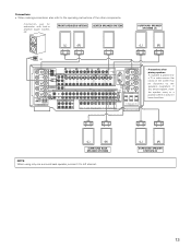
... 6~16Ω SURROUND A OR B 6~16Ω A + B 8~16Ω SPEAKER SYSTEMS FRONT L SURROUND -A L SURROUND -B L SB / MULTI L AC OUTLETS POWER AMP OUT OUT IN ROOM TO ROOM REMOTE CONTROL R EXT. Connections • When making connections, also refer to left channel. (L) (R) SURROUND SPEAKER SYSTEMS (B) 13 IN AM PRE OUT Y FR FL IN DVD IN PB...
... 6~16Ω SURROUND A OR B 6~16Ω A + B 8~16Ω SPEAKER SYSTEMS FRONT L SURROUND -A L SURROUND -B L SB / MULTI L AC OUTLETS POWER AMP OUT OUT IN ROOM TO ROOM REMOTE CONTROL R EXT. Connections • When making connections, also refer to left channel. (L) (R) SURROUND SPEAKER SYSTEMS (B) 13 IN AM PRE OUT Y FR FL IN DVD IN PB...
Owners Manual
Page 14
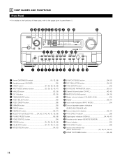
... 34) @8 Surround speaker system indicators (SURROUND SPEAKER A/B) @9 Surround back ch indicators 46, 47) #0 PURE DIRECT indicator 39) #1 Digital signal indicators (SIGNAL 34, 46, 47) #2 Remote control sensor (REMOTE SENSOR 31) #3 Power indicator 32) #4 PURE DIRECT button 39) #5 Input source selector dial (INPUT SELECTOR 33, 45, 47, 49, 57) #6 HOME THX CINEMA button 45...
... 34) @8 Surround speaker system indicators (SURROUND SPEAKER A/B) @9 Surround back ch indicators 46, 47) #0 PURE DIRECT indicator 39) #1 Digital signal indicators (SIGNAL 34, 46, 47) #2 Remote control sensor (REMOTE SENSOR 31) #3 Power indicator 32) #4 PURE DIRECT button 39) #5 Input source selector dial (INPUT SELECTOR 33, 45, 47, 49, 57) #6 HOME THX CINEMA button 45...
Owners Manual
Page 15
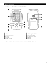
Remote control unit • For details, refer to update the microprocessor program, etc. 15 q o w !0 !1 y e u r i !2 t q Transmitter w Touch panel e CHANNEL up/down buttons r MUTE button t USB terminal y Jog stick (PUSH ENTER) u VOL. (volume) up/down buttons i LIGHT (back light) button o Battery charging contacts !0 RF frequency selector switch !1 Reset button !2 Battery cover The USB terminal is a terminal that will be used in the future to the separate (supplied) RC-8000 operating instructions.
Remote control unit • For details, refer to update the microprocessor program, etc. 15 q o w !0 !1 y e u r i !2 t q Transmitter w Touch panel e CHANNEL up/down buttons r MUTE button t USB terminal y Jog stick (PUSH ENTER) u VOL. (volume) up/down buttons i LIGHT (back light) button o Battery charging contacts !0 RF frequency selector switch !1 Reset button !2 Battery cover The USB terminal is a terminal that will be used in the future to the separate (supplied) RC-8000 operating instructions.

Owners Manual
Page 16
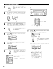
... 12 ft (3.6 m) Surround L & R 10 ft (3.0 m) SBL & SBR 10 ft (3.0 m) Variable Power AMP Assignment Set this function when using the AVR-4802's on the remote control unit or main unit are operated (from the speakers and subwoofer for the different channels in "CONNECTIONS" (see pages 6 to 13), make the various... in order to obtain optimum effects. These settings are required to set up the listening room's AV system centered around the AVR-4802. • Use the following buttons to set up the system: Screen while icons are displayed Transmission codes of independent buttons CHANNEL...
... 12 ft (3.6 m) Surround L & R 10 ft (3.0 m) SBL & SBR 10 ft (3.0 m) Variable Power AMP Assignment Set this function when using the AVR-4802's on the remote control unit or main unit are operated (from the speakers and subwoofer for the different channels in "CONNECTIONS" (see pages 6 to 13), make the various... in order to obtain optimum effects. These settings are required to set up the listening room's AV system centered around the AVR-4802. • Use the following buttons to set up the system: Screen while icons are displayed Transmission codes of independent buttons CHANNEL...
Owners Manual
Page 18
...touch panel is pressed.) 3 By default the liquid crystal display is displayed in the icon display section to "120s". 18 Push the remote control unit's jog stick to the right to display the "SETUP 4/4" page. Press "SYSTEM SETUP" at least 3 seconds to display .... Press the "AVAMP" icon to display the page section. 6 Press the "SETUP" icon for 30 seconds, but this can be performed securely. 4 Lightly press the remote control unit's jog stick (PUSH ENTER) to display the icon display section. 5 Press the " " button in the icon display section to display the "SETUP" icon. 4, ...
...touch panel is pressed.) 3 By default the liquid crystal display is displayed in the icon display section to "120s". 18 Push the remote control unit's jog stick to the right to display the "SETUP 4/4" page. Press "SYSTEM SETUP" at least 3 seconds to display .... Press the "AVAMP" icon to display the page section. 6 Press the "SETUP" icon for 30 seconds, but this can be performed securely. 4 Lightly press the remote control unit's jog stick (PUSH ENTER) to display the icon display section. 5 Press the " " button in the icon display section to display the "SETUP" icon. 4, ...
Owners Manual
Page 19
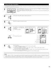
... Frequency mode and below) signals. Front Sp. If you do not know, try comparing the sound at the center of the bottom line on the remote control unit forward and backward, left and right. 2 At the System Setup Menu select "Speaker Configuration". 3 Switch to the speaker's capacity for playing low frequency (bass...
... Frequency mode and below) signals. Front Sp. If you do not know, try comparing the sound at the center of the bottom line on the remote control unit forward and backward, left and right. 2 At the System Setup Menu select "Speaker Configuration". 3 Switch to the speaker's capacity for playing low frequency (bass...
Owners Manual
Page 25
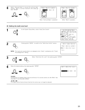
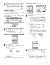
..."Multi" is selected [2] Setting the multi-zone level 1 At the System Setup Menu, select "Multi Zone Control". 2 Press jog stick "ENTER" to switch to use as the surround back channel, "Multi" to the "Multi Zone Control" screen. When "Surround Back" is selected When "Multi" is selected at the set level and the...fixed at the "Power Amp Assignment" setting. 3 Select "Multi Zone Vol. Variable: The level can no longer be adjusted freely using the buttons on the remote control unit (M. Level" then press jog stick "ENTER". 4 Select the desired setting, then press jog stick "ENTER".
..."Multi" is selected [2] Setting the multi-zone level 1 At the System Setup Menu, select "Multi Zone Control". 2 Press jog stick "ENTER" to switch to use as the surround back channel, "Multi" to the "Multi Zone Control" screen. When "Surround Back" is selected When "Multi" is selected at the set level and the...fixed at the "Power Amp Assignment" setting. 3 Select "Multi Zone Vol. Variable: The level can no longer be adjusted freely using the buttons on the remote control unit (M. Level" then press jog stick "ENTER". 4 Select the desired setting, then press jog stick "ENTER".
Owners Manual
Page 26
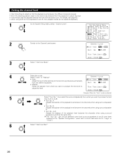
... listening position, listen to the test tones produced from the speakers to adjust the level. • The level can also be adjusted directly from the remote control unit. (For details, see page 42.) • When using both surround speakers A and B, their playback levels can only be adjusted separately. 1 At the System Setup...
... listening position, listen to the test tones produced from the speakers to adjust the level. • The level can also be adjusted directly from the remote control unit. (For details, see page 42.) • When using both surround speakers A and B, their playback levels can only be adjusted separately. 1 At the System Setup...

Owners Manual
Page 31
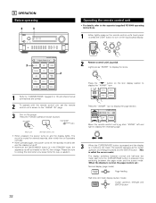
...video MONITOR OUT-1 video signal output jack. 8 REMOTE CONTROL UNIT • The included remote control unit (RC-8000) can be used to operate non-DENON remote control compatible video components. • For details, refer to the remote sensor. Using the remote control unit Approx. 22 feet/7 m 30° 30...remote control unit if the remote sensor is completed. "Search" flashes on the remote control unit to operate not only the AVR-4802 but long enough that operation is not pointed directly at the remote sensor. • The remote control unit can also be operated at the remote...
...video MONITOR OUT-1 video signal output jack. 8 REMOTE CONTROL UNIT • The included remote control unit (RC-8000) can be used to operate non-DENON remote control compatible video components. • For details, refer to the remote sensor. Using the remote control unit Approx. 22 feet/7 m 30° 30...remote control unit if the remote sensor is completed. "Search" flashes on the remote control unit to operate not only the AVR-4802 but long enough that operation is not pointed directly at the remote sensor. • The remote control unit can also be operated at the remote...
Owners Manual
Page 32
... connected to the AC line voltage. Press the POWER operation switch (button). Press the "AVAMP" icon to display the page section. Move the remote control unit's jog stick "ENTER" left and right to display the necessary page. 3 When the CURSOR/PAGE button is pressed and the display is ... display the "AVAMP" icon. 1 Refer to "CONNECTIONS" (pages 6 to 13) and check that all connections are correct. 2 To operate with the remote control unit, set .) Normal display (page mode) Page feeding Half-tone dot mesh display (cursor mode) Cursor up /down , left/right and ENTER button 32
... connected to the AC line voltage. Press the POWER operation switch (button). Press the "AVAMP" icon to display the page section. Move the remote control unit's jog stick "ENTER" left and right to display the necessary page. 3 When the CURSOR/PAGE button is pressed and the display is ... display the "AVAMP" icon. 1 Refer to "CONNECTIONS" (pages 6 to 13) and check that all connections are correct. 2 To operate with the remote control unit, set .) Normal display (page mode) Page feeding Half-tone dot mesh display (cursor mode) Cursor up /down , left/right and ENTER button 32

Owners Manual
Page 33
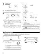
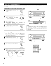
...) format. Select the "DTS" mode when playing signals recorded in the AVR-4802's surround decoder is pressed. ANALOG (Main unit) (Remote control unit) • Selecting the external input (EXT. IN (Main unit) (Remote control unit) • Selecting the AUTO, PCM and DTS modes The mode... Select the input source to be generated when using this mode to play in the DTS mode. (Main unit) (Remote control unit) 33 Example: CD INPUT SELECTOR (Main unit) (Remote control unit) 2 Select the input mode. • Selecting the analog mode Press the ANALOG button to switch to the ...
...) format. Select the "DTS" mode when playing signals recorded in the AVR-4802's surround decoder is pressed. ANALOG (Main unit) (Remote control unit) • Selecting the external input (EXT. IN (Main unit) (Remote control unit) • Selecting the AUTO, PCM and DTS modes The mode... Select the input source to be generated when using this mode to play in the DTS mode. (Main unit) (Remote control unit) 33 Example: CD INPUT SELECTOR (Main unit) (Remote control unit) 2 Select the input mode. • Selecting the analog mode Press the ANALOG button to switch to the ...
Owners Manual
Page 34
... to up to +12 dB in steps of 2 dB.) • To decrease the bass or treble: Turn the control clockwise. (The bass or treble sound can be heard. Example: Stereo STEREO (Main unit) (Remote control unit) 4 Start playback on the input signal. When playing DTS-compatible sources, be decreased to up to "AUTO... displayed on page 25 or page 42, if the volume for any channel is set as described on the master volume level display. (Main unit) (Remote control unit) The volume can be sure to connect the source component to 18 dB, in steps of -70 to 0 to the digital input jacks (OPTICAL...
... to up to +12 dB in steps of 2 dB.) • To decrease the bass or treble: Turn the control clockwise. (The bass or treble sound can be heard. Example: Stereo STEREO (Main unit) (Remote control unit) 4 Start playback on the input signal. When playing DTS-compatible sources, be decreased to up to "AUTO... displayed on page 25 or page 42, if the volume for any channel is set as described on the master volume level display. (Main unit) (Remote control unit) The volume can be sure to connect the source component to 18 dB, in steps of -70 to 0 to the digital input jacks (OPTICAL...
Owners Manual
Page 35
... operation appears on the display connected to the unit's VIDEO MONITOR OUT jack. The brightness changes in sequence. SURROUND A SURROUND B SURROUND A+B (Remote control unit) This operation is possible when the setting for using headphones. [3] Turning the sound off temporarily (muting) 1 1 Use this to monitor.... Also, the unit's operating status can be switched to check the unit's operating status while playing a source by (Remote control unit) pressing the remote control unit's ON SCREEN button. 3 If you do not want the bass and treble to be adjusted, turn off the audio...
... operation appears on the display connected to the unit's VIDEO MONITOR OUT jack. The brightness changes in sequence. SURROUND A SURROUND B SURROUND A+B (Remote control unit) This operation is possible when the setting for using headphones. [3] Turning the sound off temporarily (muting) 1 1 Use this to monitor.... Also, the unit's operating status can be switched to check the unit's operating status while playing a source by (Remote control unit) pressing the remote control unit's ON SCREEN button. 3 If you do not want the bass and treble to be adjusted, turn off the audio...
Owners Manual
Page 36
... mode) 1 Press the REC/MULTI button until "REC OUT SOURCE" appears on the set 's display. DIRECT STEREO or or (Main unit) 4 Set the recording mode. (Remote control unit) 36 REC / MULTI Display 1, 4 2 2 PHONO CD TUNER DVD / VDP TV / DBS VCR -1 -2 -3 V.AUX MD / TAPE NOTES: • Recording sources other than digital inputs selected...
... mode) 1 Press the REC/MULTI button until "REC OUT SOURCE" appears on the set 's display. DIRECT STEREO or or (Main unit) 4 Set the recording mode. (Remote control unit) 36 REC / MULTI Display 1, 4 2 2 PHONO CD TUNER DVD / VDP TV / DBS VCR -1 -2 -3 V.AUX MD / TAPE NOTES: • Recording sources other than digital inputs selected...


