
Instruction Manual
Page 2
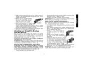
... gage. Double insulation eliminates the need for Cord Sets Volts Total Length of flammable liquids, gases, or dust. Applicable only to carry the current your product will increase the risk of electric shock. Keep cord away from heat, oil, sharp edges or moving parts. Replace damaged cords immediately. Damaged cords increase the risk of electric shock. • When operating a power tool outside, use and reduce the risk of...
... gage. Double insulation eliminates the need for Cord Sets Volts Total Length of flammable liquids, gases, or dust. Applicable only to carry the current your product will increase the risk of electric shock. Keep cord away from heat, oil, sharp edges or moving parts. Replace damaged cords immediately. Damaged cords increase the risk of electric shock. • When operating a power tool outside, use and reduce the risk of...
Instruction Manual
Page 3
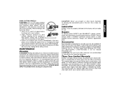
... switch on invites accidents. • Remove adjusting keys or wrenches before using. Many accidents are caused by poorly maintained tools. • Use only accessories that have the tool serviced before turning the tool on or off before making any other untrained persons. Service or maintenance performed by the manufacturer for your hair, clothing, and gloves away from the power source before plugging in moving parts. Additional Specific Safety Instructions for Grinders...
... switch on invites accidents. • Remove adjusting keys or wrenches before using. Many accidents are caused by poorly maintained tools. • Use only accessories that have the tool serviced before turning the tool on or off before making any other untrained persons. Service or maintenance performed by the manufacturer for your hair, clothing, and gloves away from the power source before plugging in moving parts. Additional Specific Safety Instructions for Grinders...
Instruction Manual
Page 4
... create an electric shock hazard. • Do not operate this tool. Tighten the handle securely. Sparks may dismount from operator, bystanders or flammable materials. If grinding wheel or accessory loosens, it run for long periods of use circular saw blades or any other accessories running over rated speed can result in this tool. Wheels and other toothed blades with a new or replacement wheel, or a new or replacement wire brush installed, hold the tool in...
... create an electric shock hazard. • Do not operate this tool. Tighten the handle securely. Sparks may dismount from operator, bystanders or flammable materials. If grinding wheel or accessory loosens, it run for long periods of use circular saw blades or any other accessories running over rated speed can result in this tool. Wheels and other toothed blades with a new or replacement wheel, or a new or replacement wire brush installed, hold the tool in...
Instruction Manual
Page 5
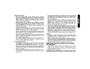
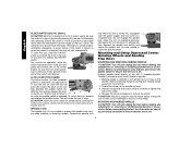
... accessory contacts a secondary surface or a surface edge. Dust Ejection System D. Spindle (not shown) (DES) E. Lock-Off Lever J. Anti-Lockup Backing Flange 4 Investigate and take corrective actions to eliminate the cause of wheel binding. • When restarting a cut for the dust exposure. Under some conditions and duration of use . Threaded Clamp Nut (D28402, D28402N) I. Spindle Lock Button K. Never attempt to remove the unit from the work with approved safety...
... accessory contacts a secondary surface or a surface edge. Dust Ejection System D. Spindle (not shown) (DES) E. Lock-Off Lever J. Anti-Lockup Backing Flange 4 Investigate and take corrective actions to eliminate the cause of wheel binding. • When restarting a cut for the dust exposure. Under some conditions and duration of use . Threaded Clamp Nut (D28402, D28402N) I. Spindle Lock Button K. Never attempt to remove the unit from the work with approved safety...

Instruction Manual
Page 6
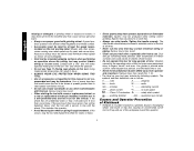
... accessories. 5 Tighten screws to use with grinder accessories. torque. Accessories It is off and unplug tool before making any adjustments or removing or installing accessories. English FIG. 1 C D28402 D28402N F D28110 D28112 S IA B J K (D28402) L L K G H K ASSEMBLY AND ADJUSTMENTS ATTACHING SIDE HANDLE The side handle (E) can be serviced and re-assembled by more than 1/4", the tool must be fitted to strip. Overtightening could cause screws to either E side of the gear case in ./lbs. Remove guard and flanges from motor...
... accessories. 5 Tighten screws to use with grinder accessories. torque. Accessories It is off and unplug tool before making any adjustments or removing or installing accessories. English FIG. 1 C D28402 D28402N F D28110 D28112 S IA B J K (D28402) L L K G H K ASSEMBLY AND ADJUSTMENTS ATTACHING SIDE HANDLE The side handle (E) can be serviced and re-assembled by more than 1/4", the tool must be fitted to strip. Overtightening could cause screws to either E side of the gear case in ./lbs. Remove guard and flanges from motor...
Instruction Manual
Page 7
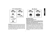
... the speed recommended on the tool warning label. Mounting instructions for a circular saw and should not be used. If it does not, it may be used with tool. Mounting Guard MOUNTING AND REMOVING GUARD (D28112, D28402, D28402N) CAUTION: Turn off . 4-1/2" Grinding Wheels Wire Wheels English Type 27 guard Type 27 guard Type 27 guard Type 27 guard backing flange Type 27 hubbed wheel 3" wire cup brush 4" wire wheel Type 27 depressed center wheel threaded clamp nut WARNING: Accessories must be above listed minimum wheel speed as shown on pages 6-7 of this manual.
... the speed recommended on the tool warning label. Mounting instructions for a circular saw and should not be used. If it does not, it may be used with tool. Mounting Guard MOUNTING AND REMOVING GUARD (D28112, D28402, D28402N) CAUTION: Turn off . 4-1/2" Grinding Wheels Wire Wheels English Type 27 guard Type 27 guard Type 27 guard Type 27 guard backing flange Type 27 hubbed wheel 3" wire cup brush 4" wire wheel Type 27 depressed center wheel threaded clamp nut WARNING: Accessories must be above listed minimum wheel speed as shown on pages 6-7 of this manual.

Instruction Manual
Page 8
... the guard by hand when the latch is pre-adjusted to provide maximum operator protection. NOTE: The guard is closed position. I ) into the desired working po sition. M 3. tioned between the spindle and the operator to the diameter of time, the guard becomes P loose, tighten the adjusting screw (P) with clamp lever in the closed . You should be able to secure the guard on the gear case. 2. To remove the guard...
... the guard by hand when the latch is pre-adjusted to provide maximum operator protection. NOTE: The guard is closed position. I ) into the desired working po sition. M 3. tioned between the spindle and the operator to the diameter of time, the guard becomes P loose, tighten the adjusting screw (P) with clamp lever in the closed . You should be able to secure the guard on the gear case. 2. To remove the guard...
Instruction Manual
Page 9
... gear case. 2. Tighten the screw to repair or replace the guard. Undetectable damage to a complete stop rotating before laying the tool down . You should not be rated for a circular saw and should be above listed minimum wheel speed as described above after any inter- See page 6 and this purpose. Turn the tool off lever is disabled, the tool may have a 7/8" arbor hole. If the lock-off A by releasing the paddle switch. MOUNTING AND REMOVING GUARD...
... gear case. 2. Tighten the screw to repair or replace the guard. Undetectable damage to a complete stop rotating before laying the tool down . You should not be rated for a circular saw and should be above listed minimum wheel speed as described above after any inter- See page 6 and this purpose. Turn the tool off lever is disabled, the tool may have a 7/8" arbor hole. If the lock-off A by releasing the paddle switch. MOUNTING AND REMOVING GUARD...
Instruction Manual
Page 10
... after any adjustments or removing or installing attachments or accessories. English SLIDER SWITCH (D28110, D28112) CAUTION: Before connecting the tool to a power supply, be sure the switch is off. To stop the tool while operat- To lock the tool on the 5/8"-11 threaded spindle. Hubbed wheels install directly on , push the lock-off . Depress the spindle lock button and use applications. Do not engage the spindle lock while the tool is released. MOUNTING NON-HUBBED WHEELS CAUTION: Turn off...
... after any adjustments or removing or installing attachments or accessories. English SLIDER SWITCH (D28110, D28112) CAUTION: Before connecting the tool to a power supply, be sure the switch is off. To stop the tool while operat- To lock the tool on the 5/8"-11 threaded spindle. Hubbed wheels install directly on , push the lock-off . Depress the spindle lock button and use applications. Do not engage the spindle lock while the tool is released. MOUNTING NON-HUBBED WHEELS CAUTION: Turn off...
Instruction Manual
Page 11
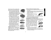
... operator. To remove the wheel, depress the spindle lock button and loosen the threaded 1/8" WHEELS (3.31mm) clamp nut with the raised section (pilot) against the wheel, it down. If a thin wheel is tightened, check the orientation of the pilot prevents the clamp nut Backing Flange from holding the wheel. Apply minimum pressure to the work surface. 4. For deeper cutting with a wrench. See the chart on the clamp nut against the wheel. Type 1 guards are installing...
... operator. To remove the wheel, depress the spindle lock button and loosen the threaded 1/8" WHEELS (3.31mm) clamp nut with the raised section (pilot) against the wheel, it down. If a thin wheel is tightened, check the orientation of the pilot prevents the clamp nut Backing Flange from holding the wheel. Apply minimum pressure to the work surface. 4. For deeper cutting with a wrench. See the chart on the clamp nut against the wheel. Type 1 guards are installing...

Instruction Manual
Page 12
... spindle lock button while Q turning the sanding disc until the sanding disc and clamp nut are complete. 1. USING SANDING BACKING PADS Choose the proper grit sandpaper for optimal finish. Begin with surface grinding. Allow the tool to reach full speed before touching the tool to withstand side pressures caused by hand. Edge grinding wheels are not designed for side pressures encountered with coarse grit discs for fast, rough material removal...
... spindle lock button while Q turning the sanding disc until the sanding disc and clamp nut are complete. 1. USING SANDING BACKING PADS Choose the proper grit sandpaper for optimal finish. Begin with surface grinding. Allow the tool to reach full speed before touching the tool to withstand side pressures caused by hand. Edge grinding wheels are not designed for side pressures encountered with coarse grit discs for fast, rough material removal...
Instruction Manual
Page 13
... tool to avoid creating gouges in a circular motion causes burning and swirling marks on the grinder spindle without moving, or moving the tool in use. A Type 27 guard is greatest when the tool operates at high speed. Move the tool constantly in damage to tighten the wheel. 3. Depress spindle lock button and use of the wire wheel or brush to tool or wheel. Sanding rate is required when using wire brushes and wheels. CAUTION: Failure to fragment from accessory wheel...
... tool to avoid creating gouges in a circular motion causes burning and swirling marks on the grinder spindle without moving, or moving the tool in use. A Type 27 guard is greatest when the tool operates at high speed. Move the tool constantly in damage to tighten the wheel. 3. Depress spindle lock button and use of the wire wheel or brush to tool or wheel. Sanding rate is required when using wire brushes and wheels. CAUTION: Failure to fragment from accessory wheel...

Instruction Manual
Page 14
... adjustments or removing or installing attachments or acces- NOTE: If, after a period of time, the guard becomes loose, tighten the adjusting screw (P) with clamp lever in the P closed position. MOUNTING CUTTING WHEELS CAUTION: Turn off as previously described to guard or mounting hub may result. Before reconnecting the tool, turn while depressing the spindle lock button. 13 Diamond blades for more information. MOUNTING CLOSED (TYPE 1) GUARD CAUTION: Turn off . Before reconnecting the tool, turn the switch on the guard...
... adjustments or removing or installing attachments or acces- NOTE: If, after a period of time, the guard becomes loose, tighten the adjusting screw (P) with clamp lever in the P closed position. MOUNTING CUTTING WHEELS CAUTION: Turn off as previously described to guard or mounting hub may result. Before reconnecting the tool, turn while depressing the spindle lock button. 13 Diamond blades for more information. MOUNTING CLOSED (TYPE 1) GUARD CAUTION: Turn off . Before reconnecting the tool, turn the switch on the guard...
Instruction Manual
Page 15
... a cut . If the tool is a necessary regular maintenance procedure. Always use identical replacement parts. Allow the tool to normal wear or tool abuse. CAUTION: Never use solvents or other qualified service personnel. This warranty gives you specific legal rights and you need assistance in the workpiece, do not change the angle of the tool. Three Year Limited Warranty DEWALT will cause the wheel to work surface before turning tool off. ALWAYS WEAR SAFETY...
... a cut . If the tool is a necessary regular maintenance procedure. Always use identical replacement parts. Allow the tool to normal wear or tool abuse. CAUTION: Never use solvents or other qualified service personnel. This warranty gives you specific legal rights and you need assistance in the workpiece, do not change the angle of the tool. Three Year Limited Warranty DEWALT will cause the wheel to work surface before turning tool off. ALWAYS WEAR SAFETY...
Instruction Manual
Page 16
... of your DEWALT Power Tool, Laser, or Nailer for any reason, you can return it within 90 days from the date of purchase with a receipt for a full refund - no questions asked. LATIN AMERICA: This warranty does not apply to the warranty, DEWALT tools are covered by our: 1 YEAR FREE SERVICE DEWALT will maintain the tool and replace worn parts caused by normal use, for free, any time...
... of your DEWALT Power Tool, Laser, or Nailer for any reason, you can return it within 90 days from the date of purchase with a receipt for a full refund - no questions asked. LATIN AMERICA: This warranty does not apply to the warranty, DEWALT tools are covered by our: 1 YEAR FREE SERVICE DEWALT will maintain the tool and replace worn parts caused by normal use, for free, any time...
Instruction Manual
Page 52
the kit box configuration; the "D" shaped air intake grill; the array of pyramids on the surface of lozenge-shaped humps on the handgrip; and the array of the tool. Especificaciones D28402, D28402N Tensión de alimentación: 120 V AC/DC ( ) Consumo de corriente: 10 A ...) 10 A 50/60 Hz 1 160 W 11 000/min DEWALT Industrial Tool Co., 701 East Joppa Road, Baltimore, MD 21286 (MAR06) Form No. 641881-00 D28110, D28112, D28402, D28402N Copyright © 2005, 2006 DEWALT The following are trademarks for one or more DEWALT power tools: the yellow and black color scheme;
the kit box configuration; the "D" shaped air intake grill; the array of pyramids on the surface of lozenge-shaped humps on the handgrip; and the array of the tool. Especificaciones D28402, D28402N Tensión de alimentación: 120 V AC/DC ( ) Consumo de corriente: 10 A ...) 10 A 50/60 Hz 1 160 W 11 000/min DEWALT Industrial Tool Co., 701 East Joppa Road, Baltimore, MD 21286 (MAR06) Form No. 641881-00 D28110, D28112, D28402, D28402N Copyright © 2005, 2006 DEWALT The following are trademarks for one or more DEWALT power tools: the yellow and black color scheme;

Parts Diagram
Page 2
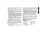
... 28 29 70 Part Number Parts List for current parts information. Please visit www.dewaltservicenet.com for D28112 Type 1 Description Qty Required 623584-12S ARMATURE ASSY. 1 623599-01 FIELD CASE 1 N012328SV GEAR CASE ASSY 1 659967-00 GEAR 1 330065-31 SCREW 9 648743-00 ARM 2 623592-00 FELT SEAL 4 650916-01 BRUSH 2 623589-00 BRUSH SPRING 2 623591-00 CAP 2 593685-00 SCREW 2 625243-00SV HANDLE SET 1 945614-00 SWITCH,ON/OFF...
... 28 29 70 Part Number Parts List for current parts information. Please visit www.dewaltservicenet.com for D28112 Type 1 Description Qty Required 623584-12S ARMATURE ASSY. 1 623599-01 FIELD CASE 1 N012328SV GEAR CASE ASSY 1 659967-00 GEAR 1 330065-31 SCREW 9 648743-00 ARM 2 623592-00 FELT SEAL 4 650916-01 BRUSH 2 623589-00 BRUSH SPRING 2 623591-00 CAP 2 593685-00 SCREW 2 625243-00SV HANDLE SET 1 945614-00 SWITCH,ON/OFF...

Parts Diagram
Page 3
... 92 93 95 96 800 800 Part Number 623564-00 330003-60 623617-00 ...Parts List for current parts information. Parts list, pricing, and availability subject to change. All Rights Reserved. RETAINER 1 SLINGER 1 BALL BEARING 1 BEARING CUP 1 FIELD 1 FAN BAFFLE 1 SCREW 4 GASKET 1 SLEEVE,RUBBER 1 GEAR CASE COVER 1 SCREW 4 SCREW 1 TERMINAL 2 WRENCH 1 SIDE HANDLE 1 LINK 1 BAR 1 SWITCH BUTTON 1 O-RING 1 O-RING 1 HEX WRENCH 1 SPINDLE LOCK BUTTON 1 GREASE 1 GREASE 1 COPYRIGHT© 2005. Page 2 Please visit www.dewaltservicenet.com for D28112 Type...
... 92 93 95 96 800 800 Part Number 623564-00 330003-60 623617-00 ...Parts List for current parts information. Parts list, pricing, and availability subject to change. All Rights Reserved. RETAINER 1 SLINGER 1 BALL BEARING 1 BEARING CUP 1 FIELD 1 FAN BAFFLE 1 SCREW 4 GASKET 1 SLEEVE,RUBBER 1 GEAR CASE COVER 1 SCREW 4 SCREW 1 TERMINAL 2 WRENCH 1 SIDE HANDLE 1 LINK 1 BAR 1 SWITCH BUTTON 1 O-RING 1 O-RING 1 HEX WRENCH 1 SPINDLE LOCK BUTTON 1 GREASE 1 GREASE 1 COPYRIGHT© 2005. Page 2 Please visit www.dewaltservicenet.com for D28112 Type...

Parts Diagram
Page 4
Parts list, pricing, and availability subject to change. Page 3 All Rights Reserved. Please visit www.dewaltservicenet.com for D28112 Type 1 Description Qty Required GREASE, 7LBS 1 GREASE,1 LB. 1 TORX DRIVER 1 SHIM 1 GUARD 1 4-1/2X1/4 METL 1 COPYRIGHT© 2005. Item Number 800 800 836 846 856 856 Part Number 429954-00 429954-01 233804-36 5140030-98 643772-00 DW4514 Parts List for current parts information.
Parts list, pricing, and availability subject to change. Page 3 All Rights Reserved. Please visit www.dewaltservicenet.com for D28112 Type 1 Description Qty Required GREASE, 7LBS 1 GREASE,1 LB. 1 TORX DRIVER 1 SHIM 1 GUARD 1 4-1/2X1/4 METL 1 COPYRIGHT© 2005. Item Number 800 800 836 846 856 856 Part Number 429954-00 429954-01 233804-36 5140030-98 643772-00 DW4514 Parts List for current parts information.


