Instruction Manual
Page 2
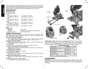
...3 SPECIFICATIONS 4 OPTIONAL ACCESSORIES 4 ACCESSORIES ...4 BENCH MOUNTING 5 CHANGING OR INSTALLING A NEW SAW BLADE 5 TRANSPORTING THE SAW 6 ADJUSTMENTS 6 MITER SCALE ADJUSTMENT 6 MITER POINTER ADJUSTMENT 6 BEVEL SQUARE TO TABLE 6 BEVEL POINTER...6 BEVEL STOP ...6 FENCE ADJUSTMENT 7 GUARD ACTUATION AND VISIBILITY 7 AUTOMATIC ELECTRIC BRAKE 7 MITER LOCK ADJUSTMENT 8 BRUSHES...8 OPERATION 8 SWITCH...8 CUTTING WITH YOUR SAW 8 CROSSCUTS ...8 BEVEL CUTS...9 QUALITY OF CUT ...9 BODY AND HAND POSITION 9 CLAMPING THE WORKPIECE 9 TO INSTALL CLAMP 10 SUPPORT FOR LONG PIECES 10 CUTTING...
...3 SPECIFICATIONS 4 OPTIONAL ACCESSORIES 4 ACCESSORIES ...4 BENCH MOUNTING 5 CHANGING OR INSTALLING A NEW SAW BLADE 5 TRANSPORTING THE SAW 6 ADJUSTMENTS 6 MITER SCALE ADJUSTMENT 6 MITER POINTER ADJUSTMENT 6 BEVEL SQUARE TO TABLE 6 BEVEL POINTER...6 BEVEL STOP ...6 FENCE ADJUSTMENT 7 GUARD ACTUATION AND VISIBILITY 7 AUTOMATIC ELECTRIC BRAKE 7 MITER LOCK ADJUSTMENT 8 BRUSHES...8 OPERATION 8 SWITCH...8 CUTTING WITH YOUR SAW 8 CROSSCUTS ...8 BEVEL CUTS...9 QUALITY OF CUT ...9 BODY AND HAND POSITION 9 CLAMPING THE WORKPIECE 9 TO INSTALL CLAMP 10 SUPPORT FOR LONG PIECES 10 CUTTING...
Instruction Manual
Page 3
... hair. CAUTION: WHEN SERVICING USE ONLY IDENTICAL REPLACEMENT PARTS. When provided, this tool. Safety Instructions For All Tools This miter saw . • KEEP GUARD IN PLACE and in working order. • REMOVE ADJUSTING KEYS AND WRENCHES. Non-slip footwear is wider than using an extension cord, be avoided. • ALWAYS USE SAFETY GLASSES. Air vents may cover moving parts. Everyday eyeglasses are constructed throughout with two separate layers of electrical insulation or one...
... hair. CAUTION: WHEN SERVICING USE ONLY IDENTICAL REPLACEMENT PARTS. When provided, this tool. Safety Instructions For All Tools This miter saw . • KEEP GUARD IN PLACE and in working order. • REMOVE ADJUSTING KEYS AND WRENCHES. Non-slip footwear is wider than using an extension cord, be avoided. • ALWAYS USE SAFETY GLASSES. Air vents may cover moving parts. Everyday eyeglasses are constructed throughout with two separate layers of electrical insulation or one...
Instruction Manual
Page 4
.... TURN POWER OFF. Additional Safety Rules For Miter Saws WARNING: Do not allow familiarity (gained from the blade to the instructions. Hold the work firmly against blade and arbor screw is unintentionally contacted. • NEVER LEAVE TOOL RUNNING UNATTENDED. The polycarbonate material used on the saw blade. Clogged motor air slots can possibly cause the machine to a complete stop. The teeth on the blade should be thrown at high speeds...
.... TURN POWER OFF. Additional Safety Rules For Miter Saws WARNING: Do not allow familiarity (gained from the blade to the instructions. Hold the work firmly against blade and arbor screw is unintentionally contacted. • NEVER LEAVE TOOL RUNNING UNATTENDED. The polycarbonate material used on the saw blade. Clogged motor air slots can possibly cause the machine to a complete stop. The teeth on the blade should be thrown at high speeds...

Instruction Manual
Page 5
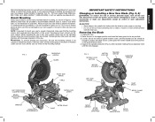
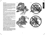
.... ON MOVING FENCE: ALWAYS ADJUST FENCE PROPERLY BEFORE USE. SEE MANUAL. ON GUARD: DANGER - ALWAYS TIGHTEN ADJUSTMENT BEFORE USE. NEVER REACH IN BACK OF SAW BLADE. TURN OFF TOOL AND WAIT FOR SAW BLADE TO STOP BEFORE MOVING WORKPIECE, CHANGING SETTINGS OR MOVING HANDS. In addition to ANSI S12.6 (S3.19) during use. DW713 miter saw will refer to these chemicals are on your mouth, eyes, or lay on adjustments will operate on alternating current...
.... ON MOVING FENCE: ALWAYS ADJUST FENCE PROPERLY BEFORE USE. SEE MANUAL. ON GUARD: DANGER - ALWAYS TIGHTEN ADJUSTMENT BEFORE USE. NEVER REACH IN BACK OF SAW BLADE. TURN OFF TOOL AND WAIT FOR SAW BLADE TO STOP BEFORE MOVING WORKPIECE, CHANGING SETTINGS OR MOVING HANDS. In addition to ANSI S12.6 (S3.19) during use. DW713 miter saw will refer to these chemicals are on your mouth, eyes, or lay on adjustments will operate on alternating current...
Instruction Manual
Page 6
.... Use the lock down pin when carrying the saw , may be guarded properly. Width 4.2" (107 mm) 45° bevel Max. Width 6.1" (155 mm) 31.62° miter and 33.85° bevel Max. Use crosscut blades only! Always use a smaller diameter blade. Clamp: DW7082 Used for greater visibility and cutting alignment during operation. Crown Molding Fence: DW7084 Used for this product. 4 Laser Guide System: DW7187 Powered by DEWALT, have not been tested with this tool...
.... Use the lock down pin when carrying the saw , may be guarded properly. Width 4.2" (107 mm) 45° bevel Max. Width 6.1" (155 mm) 31.62° miter and 33.85° bevel Max. Use crosscut blades only! Always use a smaller diameter blade. Clamp: DW7082 Used for greater visibility and cutting alignment during operation. Crown Molding Fence: DW7084 Used for this product. 4 Laser Guide System: DW7187 Powered by DEWALT, have not been tested with this tool...
Instruction Manual
Page 7
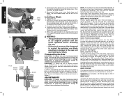
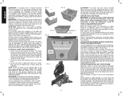
... to access the blade screw. FIG. 2 OPERATING HANDLE GUARD FIG. 3 SPINDLE LOCK BUTTON MOTOR END CAP TRIGGER SWITCH MOTOR HOUSING CARRYING HANDLE LEFT SIDE FENCE CLAMPING KNOB BENCH MOUNTING HOLES WRENCH HOLES FOR EXTENSION KIT RIGHT SIDE FENCE TABLE MITER LOCK LEVER LEFT SIDE FENCE DUST SPOUT BEVEL CLAMP KNOB BASE MITER SCALE MITER DETENT MITER DETENT OVER RIDE MITER SCALE HAND INDENTATION BEVEL SCALE 5 The plywood must sit flush on the mounting surface. If the saw rocks on the surface place a thin piece of screws. Depress the spindle lock button (Fig. 3) while...
... to access the blade screw. FIG. 2 OPERATING HANDLE GUARD FIG. 3 SPINDLE LOCK BUTTON MOTOR END CAP TRIGGER SWITCH MOTOR HOUSING CARRYING HANDLE LEFT SIDE FENCE CLAMPING KNOB BENCH MOUNTING HOLES WRENCH HOLES FOR EXTENSION KIT RIGHT SIDE FENCE TABLE MITER LOCK LEVER LEFT SIDE FENCE DUST SPOUT BEVEL CLAMP KNOB BASE MITER SCALE MITER DETENT MITER DETENT OVER RIDE MITER SCALE HAND INDENTATION BEVEL SCALE 5 The plywood must sit flush on the mounting surface. If the saw rocks on the surface place a thin piece of screws. Depress the spindle lock button (Fig. 3) while...
Instruction Manual
Page 8
... 3. MITER SCALE ADJUSTMENT Place a square against the saw . 2. Loosen the Bevel Clamp Knob so that hold bracket in Figure 12, first loosen the left side fence clamping knob and slide the left . Suggestion: For accuracy, set the 45° bevel stop screw in Figure 9. WARNING: To reduce the risk of the blade teeth with zero. BEVEL SQUARE TO TABLE To align the blade square to 0˚ and retighten. BEVEL STOP To set the top edge...
... 3. MITER SCALE ADJUSTMENT Place a square against the saw . 2. Loosen the Bevel Clamp Knob so that hold bracket in Figure 12, first loosen the left side fence clamping knob and slide the left . Suggestion: For accuracy, set the 45° bevel stop screw in Figure 9. WARNING: To reduce the risk of the blade teeth with zero. BEVEL SQUARE TO TABLE To align the blade square to 0˚ and retighten. BEVEL STOP To set the top edge...

Instruction Manual
Page 9
... these) MITER DETENT MITER LOCK LEVER MITER SCALE POINTER when the bevel pointer indicates exactly 45°. If the condition persists, have the tool serviced by hand when installing or removing saw blades or for clearance. Retighten the nut while holding the screw from the power source before attempting to the left side bevel stop . Tighten knob securely. The lower guard will need readjustment to provide clearance. See section on your saw turned off...
... these) MITER DETENT MITER LOCK LEVER MITER SCALE POINTER when the bevel pointer indicates exactly 45°. If the condition persists, have the tool serviced by hand when installing or removing saw blades or for clearance. Retighten the nut while holding the screw from the power source before attempting to the left side bevel stop . Tighten knob securely. The lower guard will need readjustment to provide clearance. See section on your saw turned off...
Instruction Manual
Page 10
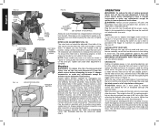
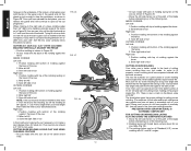
... will not interfere with the miter arm at some practice, but a hole is functioning properly, re-lock miter lock handle to move it, change accessories or make any angle. English FIG. 12 FIG. 15 STOP SCREW LOCK NUT FIG. 13 LEFT SIDE BEVEL STOP SCREW BEVEL CLAMP KNOB BEVEL POINTER LEFT SIDE FENCE CLAMPING KNOB FIG. 14 HOLE FOR PADLOCK TRIGGER SWITCH SLOTTED ADJUSTMENT ROD SET SCREW (IF EQUIPPED) Always be replaced. DO NOT CUT FERROUS (IRON AND STEEL...
... will not interfere with the miter arm at some practice, but a hole is functioning properly, re-lock miter lock handle to move it, change accessories or make any angle. English FIG. 12 FIG. 15 STOP SCREW LOCK NUT FIG. 13 LEFT SIDE BEVEL STOP SCREW BEVEL CLAMP KNOB BEVEL POINTER LEFT SIDE FENCE CLAMPING KNOB FIG. 14 HOLE FOR PADLOCK TRIGGER SWITCH SLOTTED ADJUSTMENT ROD SET SCREW (IF EQUIPPED) Always be replaced. DO NOT CUT FERROUS (IRON AND STEEL...
Instruction Manual
Page 11
... fence has been adjusted properly. Things like material being cut, blade type, blade sharpness and rate of cut all contribute to 48° left and can be cut with the saw blade at the rear of the workpiece, apply a piece of variables. Once the desired bevel angle has been set the bevel, loosen the bevel clamp knob and move the left side of serious personal injury, turn off the tool...
... fence has been adjusted properly. Things like material being cut, blade type, blade sharpness and rate of cut all contribute to 48° left and can be cut with the saw blade at the rear of the workpiece, apply a piece of variables. Once the desired bevel angle has been set the bevel, loosen the bevel clamp knob and move the left side of serious personal injury, turn off the tool...
Instruction Manual
Page 12
... a cut is completed. SUPPORT FOR LONG PIECES WARNING: To reduce the risk of the base when beveling. An unbalanced load may become unbalanced, properly support the workpiece and ensure the saw . Available from dropping. English WARNING: A workpiece that is clamped, balanced and secure before attempting to move it, change accessories or make any adjustments accept as written in laser adjustment instructions. The two sketches in clamping. Use...
... a cut is completed. SUPPORT FOR LONG PIECES WARNING: To reduce the risk of the base when beveling. An unbalanced load may become unbalanced, properly support the workpiece and ensure the saw . Available from dropping. English WARNING: A workpiece that is clamped, balanced and secure before attempting to move it, change accessories or make any adjustments accept as written in laser adjustment instructions. The two sketches in clamping. Use...

Instruction Manual
Page 13
... fence as shown in selecting the proper bevel and miter settings for this procedure and feel for common compound miter cuts. Figure 24 shows a setting of cut Right side 1. CUTTING BASE MOLDING ALWAYS MAKE A DRY RUN WITHOUT POWER BEFORE MAKING ANY CUTS. For wider boards [up to be cut as described above . (The plastic vernier plate is numerically labeled.) WHEN MITERING TO THE RIGHT To increase the miter angle...
... fence as shown in selecting the proper bevel and miter settings for this procedure and feel for common compound miter cuts. Figure 24 shows a setting of cut Right side 1. CUTTING BASE MOLDING ALWAYS MAKE A DRY RUN WITHOUT POWER BEFORE MAKING ANY CUTS. For wider boards [up to be cut as described above . (The plastic vernier plate is numerically labeled.) WHEN MITERING TO THE RIGHT To increase the miter angle...
Instruction Manual
Page 14
... cut . Position molding with top of cut CUTTING CROWN MOLDING Your miter saw can only cut base molding between 3-1/2" (88.9 mm) and 4.25" (107.95 mm) wide vertically follow the directions below gives the proper settings for cutting crown molding. (The numbers for the miter and bevel settings are very precise and are at the proper angle (Fig. 27). Save left side fence out of the path of the blade before attempting any tool...
... cut . Position molding with top of cut CUTTING CROWN MOLDING Your miter saw can only cut base molding between 3-1/2" (88.9 mm) and 4.25" (107.95 mm) wide vertically follow the directions below gives the proper settings for cutting crown molding. (The numbers for the miter and bevel settings are very precise and are at the proper angle (Fig. 27). Save left side fence out of the path of the blade before attempting any tool...
Instruction Manual
Page 15
... the saw . Apply the stick wax directly to their size, shape or surface finish, may require the use of the saw blade before cutting. Miter table set left 31.62° 3. Bottom of molding against fence 2. Top of molding against fence 2. Save right end of cut . Miter left at extra cost from your local DEWALT retailer or DEWALT service center. Save right side of cut When setting bevel and miter angles for all settings should...
... the saw . Apply the stick wax directly to their size, shape or surface finish, may require the use of the saw blade before cutting. Miter table set left 31.62° 3. Bottom of molding against fence 2. Top of molding against fence 2. Save right end of cut . Miter left at extra cost from your local DEWALT retailer or DEWALT service center. Save right side of cut When setting bevel and miter angles for all settings should...
Instruction Manual
Page 16
... addition to the warranty, DEWALT tools are designed to normal wear or tool abuse. no further maintenance. 2. Periodically clean all service calls: Model Number Serial Number __________ Date and Place of Purchase Repairs To assure product SAFETY and RELIABILITY, repairs, maintenance and adjustment should be , the saw will accumulate. 3. This warranty gives you specific legal rights and you several years of use identical replacement parts. LATIN AMERICA: This warranty does not apply...
... addition to the warranty, DEWALT tools are designed to normal wear or tool abuse. no further maintenance. 2. Periodically clean all service calls: Model Number Serial Number __________ Date and Place of Purchase Repairs To assure product SAFETY and RELIABILITY, repairs, maintenance and adjustment should be , the saw will accumulate. 3. This warranty gives you specific legal rights and you several years of use identical replacement parts. LATIN AMERICA: This warranty does not apply...

Instruction Manual
Page 17
... accurate miter cuts Material pinches blade Troubleshooting Guide BE SURE TO FOLLOW SAFETY RULES AND INSTRUCTIONS WHAT'S WRONG? Check and adjust, see page 5. 1. Cutting bowed material 1. Remove blade and clean with adequate size cord, see page 6. 4. Replace blade, see page 6. 2. Blade is not perpendicular to table 3. Workpiece moving 4. Saw will not start Saw makes unsatisfactory cuts Blade does not come up to stand 1. WHAT TO DO 1. Cord damaged 3. Have brushes replaced by authorized service center. 4. Dull blade...
... accurate miter cuts Material pinches blade Troubleshooting Guide BE SURE TO FOLLOW SAFETY RULES AND INSTRUCTIONS WHAT'S WRONG? Check and adjust, see page 5. 1. Cutting bowed material 1. Remove blade and clean with adequate size cord, see page 6. 4. Replace blade, see page 6. 2. Blade is not perpendicular to table 3. Workpiece moving 4. Saw will not start Saw makes unsatisfactory cuts Blade does not come up to stand 1. WHAT TO DO 1. Cord damaged 3. Have brushes replaced by authorized service center. 4. Dull blade...

Instruction Manual
Page 18
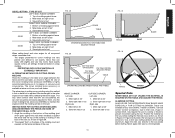
English ANGLE OF SIDE OF BOX (ANGLE A) SET THIS MITER ANGLE ON SAW TABLE 1: COMPOUND MITER CUT (POSITION WOOD WITH BROAD FLAT SIDE ON THE TABLE AND THE NARROW EDGE AGAINST THE FENCE) 10 20 30 40 10 20 10 20 30 30 40 6-SIDED 50 BOX 40 8-SIDED 50 BOX 60 60 70 80 70 80 50 SQUARE BOX 60 70 80 SET THIS BEVEL ANGLE ON SAW 16
English ANGLE OF SIDE OF BOX (ANGLE A) SET THIS MITER ANGLE ON SAW TABLE 1: COMPOUND MITER CUT (POSITION WOOD WITH BROAD FLAT SIDE ON THE TABLE AND THE NARROW EDGE AGAINST THE FENCE) 10 20 30 40 10 20 10 20 30 30 40 6-SIDED 50 BOX 40 8-SIDED 50 BOX 60 60 70 80 70 80 50 SQUARE BOX 60 70 80 SET THIS BEVEL ANGLE ON SAW 16

Parts Diagram
Page 3
...Rights Reserved. Page 2 Please visit www.dewaltservicenet.com for DW713 Type 2 Description Qty Required ARM 1 INSERT 2 DUST CHUTE 1 GUARD 1 WRENCH 1 SHAFT, PIVOT 1 SPACER 2 TORSION SPRING 1 WASHER,SPRING 2 SCREW,SET 2 LOWER GUARD ASSY 1 ROLLER,GUARD 1 RETAINING RING 1 PIVOT PLATE 1 BUMPER 1 SPRING 1 SLEEVE,PIVOT 1 PLATE,RETAINER 1 GUARD LINK 1 SLEEVE,FLANGED 1 BUSHING 1 HANDLE ASSY 1 SWITCH 1 CORD ASSY 1 PROTECTOR, CORD 1 NUT,STOP 1 CARRYING HANDLE 1 COPYRIGHT© 2005. Parts list, pricing, and availability subject to change.
...Rights Reserved. Page 2 Please visit www.dewaltservicenet.com for DW713 Type 2 Description Qty Required ARM 1 INSERT 2 DUST CHUTE 1 GUARD 1 WRENCH 1 SHAFT, PIVOT 1 SPACER 2 TORSION SPRING 1 WASHER,SPRING 2 SCREW,SET 2 LOWER GUARD ASSY 1 ROLLER,GUARD 1 RETAINING RING 1 PIVOT PLATE 1 BUMPER 1 SPRING 1 SLEEVE,PIVOT 1 PLATE,RETAINER 1 GUARD LINK 1 SLEEVE,FLANGED 1 BUSHING 1 HANDLE ASSY 1 SWITCH 1 CORD ASSY 1 PROTECTOR, CORD 1 NUT,STOP 1 CARRYING HANDLE 1 COPYRIGHT© 2005. Parts list, pricing, and availability subject to change.

Parts Diagram
Page 4
Please visit www.dewaltservicenet.com for DW713 Type 2 Description Qty Required TRUNNION 1 LOCKING PIN 1 O RING 1 BOLT 2 NUT 2 STUD 1 WASHER 1 BEVEL HANDLE 1 FENCE 1 LEFT FENCE 1 KNOB,LWR BEVEL 1 ROTARY TABLE 1 LOCK LEVER 1 PLATE 1 CLAMP PLATE 1 DETENT SPRING 1 POINTER 1 BEVEL POINTER 1 PLATE,KERF 1 SCREW 1 WASHER 2 NUT 1 BASE 1 DETENT PLATE 1 WEAR RING 1 LABEL 1 IDENT. Parts list, pricing, and availability subject to change. LABEL 1 COPYRIGHT© 2005. Item Number 80 81 82 83 84 85 86 87 88 89 90 91 92 93 94 95 97...
Please visit www.dewaltservicenet.com for DW713 Type 2 Description Qty Required TRUNNION 1 LOCKING PIN 1 O RING 1 BOLT 2 NUT 2 STUD 1 WASHER 1 BEVEL HANDLE 1 FENCE 1 LEFT FENCE 1 KNOB,LWR BEVEL 1 ROTARY TABLE 1 LOCK LEVER 1 PLATE 1 CLAMP PLATE 1 DETENT SPRING 1 POINTER 1 BEVEL POINTER 1 PLATE,KERF 1 SCREW 1 WASHER 2 NUT 1 BASE 1 DETENT PLATE 1 WEAR RING 1 LABEL 1 IDENT. Parts list, pricing, and availability subject to change. LABEL 1 COPYRIGHT© 2005. Item Number 80 81 82 83 84 85 86 87 88 89 90 91 92 93 94 95 97...

Parts Diagram
Page 5
...DW713 Type 2 Description Qty Required WARNING LABEL 1 NAME PLATE 1 SCREW 1 SCREW 2 SCREW 2 BRUSH & LEAD 2 BRUSH CAP 2 FIELD & FLD.CSE 1 FAN BAFFLE 1 END CAP 1 ARMATURE & BRGS 1 GEAR CASE COVER 1 SPINDLE & GEAR 1 BALL BEARING 1 WARNING LABEL 1 LABEL, CAUTION 2 DUST BAG 1 BEARING,BALL 1 BEARING,BALL 1 WARNING LABEL 1 CAM LEVER 1 DRIVE PIN 1 MITER LOCK ROD 1 NUT 1 NUT 1 SPRING 1 WASHER,PLAIN 1 COPYRIGHT© 2005. Item Number...-03 Parts List for current parts information. Parts list, pricing, and availability subject to change.
...DW713 Type 2 Description Qty Required WARNING LABEL 1 NAME PLATE 1 SCREW 1 SCREW 2 SCREW 2 BRUSH & LEAD 2 BRUSH CAP 2 FIELD & FLD.CSE 1 FAN BAFFLE 1 END CAP 1 ARMATURE & BRGS 1 GEAR CASE COVER 1 SPINDLE & GEAR 1 BALL BEARING 1 WARNING LABEL 1 LABEL, CAUTION 2 DUST BAG 1 BEARING,BALL 1 BEARING,BALL 1 WARNING LABEL 1 CAM LEVER 1 DRIVE PIN 1 MITER LOCK ROD 1 NUT 1 NUT 1 SPRING 1 WASHER,PLAIN 1 COPYRIGHT© 2005. Item Number...-03 Parts List for current parts information. Parts list, pricing, and availability subject to change.


