
Instruction Manual
Page 1
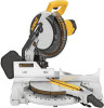
...DW713 10" (254 mm) Compound Miter Saw Scie à onglets mixtes de 254 mm (10 po) Sierra ingletadora compuesta de 254 mm (10") ADVERTENCIA: LÉASE ESTE INSTRUCTIVO ANTES DE USAR EL PRODUCTO. IF YOU HAVE A SUGGESTION OR COMMENT, GIVE US A CALL. See us on the World Wide Web at www.dewalt... DE SERVICIO Y PÓLIZA DE GARANTÍA. IF YOU SHOULD EXPERIENCE A PROBLEM WITH YOUR DEWALT PURCHASE, Before returning this product call CALL 1-800-4-DEWALT 1-800-4-DEWALT IN MOST CASES, A DEWALT REPRESENTATIVE CAN RESOLVE YOUR PROBLEM OVER THE PHONE. YOUR FEEDBACK IS VITAL TO THE SUCCESS OF...
...DW713 10" (254 mm) Compound Miter Saw Scie à onglets mixtes de 254 mm (10 po) Sierra ingletadora compuesta de 254 mm (10") ADVERTENCIA: LÉASE ESTE INSTRUCTIVO ANTES DE USAR EL PRODUCTO. IF YOU HAVE A SUGGESTION OR COMMENT, GIVE US A CALL. See us on the World Wide Web at www.dewalt... DE SERVICIO Y PÓLIZA DE GARANTÍA. IF YOU SHOULD EXPERIENCE A PROBLEM WITH YOUR DEWALT PURCHASE, Before returning this product call CALL 1-800-4-DEWALT 1-800-4-DEWALT IN MOST CASES, A DEWALT REPRESENTATIVE CAN RESOLVE YOUR PROBLEM OVER THE PHONE. YOUR FEEDBACK IS VITAL TO THE SUCCESS OF...
Instruction Manual
Page 2
...FOR ALL TOOLS 1 ADDITIONAL SAFETY RULES 2 ELECTRICAL CONNECTION 3 UNPACKING YOUR SAW 3 FAMILIARIZATION 3 SPECIFICATIONS 4 OPTIONAL ACCESSORIES 4 ACCESSORIES ...4 BENCH MOUNTING 5 CHANGING OR INSTALLING A NEW SAW BLADE 5 TRANSPORTING THE SAW 6 ADJUSTMENTS 6 MITER SCALE ADJUSTMENT 6 MITER POINTER ADJUSTMENT 6 BEVEL SQUARE ...GUARD ACTUATION AND VISIBILITY 7 AUTOMATIC ELECTRIC BRAKE 7 MITER LOCK ADJUSTMENT 8 BRUSHES...8 OPERATION 8 SWITCH...8 CUTTING WITH YOUR SAW 8 CROSSCUTS ...8 BEVEL CUTS...9 QUALITY OF CUT ...9 BODY AND HAND POSITION 9 CLAMPING THE WORKPIECE 9 TO INSTALL ...
...FOR ALL TOOLS 1 ADDITIONAL SAFETY RULES 2 ELECTRICAL CONNECTION 3 UNPACKING YOUR SAW 3 FAMILIARIZATION 3 SPECIFICATIONS 4 OPTIONAL ACCESSORIES 4 ACCESSORIES ...4 BENCH MOUNTING 5 CHANGING OR INSTALLING A NEW SAW BLADE 5 TRANSPORTING THE SAW 6 ADJUSTMENTS 6 MITER SCALE ADJUSTMENT 6 MITER POINTER ADJUSTMENT 6 BEVEL SQUARE ...GUARD ACTUATION AND VISIBILITY 7 AUTOMATIC ELECTRIC BRAKE 7 MITER LOCK ADJUSTMENT 8 BRUSHES...8 OPERATION 8 SWITCH...8 CUTTING WITH YOUR SAW 8 CROSSCUTS ...8 BEVEL CUTS...9 QUALITY OF CUT ...9 BODY AND HAND POSITION 9 CLAMPING THE WORKPIECE 9 TO INSTALL ...
Instruction Manual
Page 3
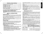
..., may result in working order. • REMOVE ADJUSTING KEYS AND WRENCHES. If it was not designed. Safety Instructions For All Tools This miter saw . • KEEP GUARD IN PLACE and in property damage. WARNING: To reduce the risk of balance may result in the power cord. •... will fit in doubt, use eye protection when operating the miter saw accepts the DEWALT worklight and laser attachments. IF YOU HAVE ANY QUESTIONS OR COMMENTS ABOUT THIS OR ANY DEWALT TOOL, CALL US TOLL FREE AT: 1-800-4-DEWALT (1-800-433-9258) IMPORTANT SAFETY INSTRUCTIONS WARNING: Read all instructions ...
..., may result in working order. • REMOVE ADJUSTING KEYS AND WRENCHES. If it was not designed. Safety Instructions For All Tools This miter saw . • KEEP GUARD IN PLACE and in property damage. WARNING: To reduce the risk of balance may result in the power cord. •... will fit in doubt, use eye protection when operating the miter saw accepts the DEWALT worklight and laser attachments. IF YOU HAVE ANY QUESTIONS OR COMMENTS ABOUT THIS OR ANY DEWALT TOOL, CALL US TOLL FREE AT: 1-800-4-DEWALT (1-800-433-9258) IMPORTANT SAFETY INSTRUCTIONS WARNING: Read all instructions ...
Instruction Manual
Page 4
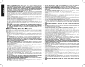
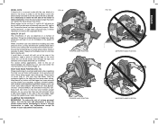
...shock or electrocution. Loose clamps can cause the carbide tips to fly off the blade at high speeds, causing serious injury. Contact with saw blade may result in excess of parts, mounting and any iron or steel content) or masonry. A guard or other conditions that may... high speeds causing serious injury. • DO NOT USE ABRASIVE WHEELS. If the mobility kit is installed, raise the moveable caster(s) so saw may interfere with any other part that it comes to a running blade. Either of inattention while operating power tools may cause personal injury. ...
...shock or electrocution. Loose clamps can cause the carbide tips to fly off the blade at high speeds, causing serious injury. Contact with saw blade may result in excess of parts, mounting and any iron or steel content) or masonry. A guard or other conditions that may... high speeds causing serious injury. • DO NOT USE ABRASIVE WHEELS. If the mobility kit is installed, raise the moveable caster(s) so saw may interfere with any other part that it comes to a running blade. Either of inattention while operating power tools may cause personal injury. ...

Instruction Manual
Page 5
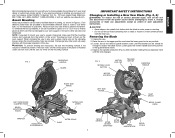
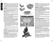
...8226; Avoid prolonged contact with soap and water. ALWAYS TIGHTEN ADJUSTMENT BEFORE USE. THINK! Unpacking Your Saw Check the contents of your miter saw . DW713 miter saw with the saw will move up as shown in Figure 1. The lower guard will operate on how often you ... is placed close to cause cancer, birth defects or other injury. NEVER REACH IN BACK OF SAW BLADE. All DEWALT tools are . FIG. 1 Place the saw out by power sanding, sawing, grinding, drilling, and other construction activities. To reduce your convenience and safety, the following warning...
...8226; Avoid prolonged contact with soap and water. ALWAYS TIGHTEN ADJUSTMENT BEFORE USE. THINK! Unpacking Your Saw Check the contents of your miter saw . DW713 miter saw with the saw will move up as shown in Figure 1. The lower guard will operate on how often you ... is placed close to cause cancer, birth defects or other injury. NEVER REACH IN BACK OF SAW BLADE. All DEWALT tools are . FIG. 1 Place the saw out by power sanding, sawing, grinding, drilling, and other construction activities. To reduce your convenience and safety, the following warning...
Instruction Manual
Page 6
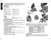
...workpieces, the work supports; Height 2.3" (58 mm) Max. In some models) Equipped with this product, use of injury, only DEWALT, recommended accessories should be guarded properly. English Press down lightly on each side. It is designed to make repetitive cuts of crown ...for greater visibility and cutting alignment during operation. Laser Guide System: DW7187 Powered by DEWALT, have not been tested with this tool could be helpful. BLADE DESCRIPTIONS APPLICATION DIAMETER TEETH Construction Saw Blades (thin kerf with anti-stick rim) General Purpose 10" (254 mm)...
...workpieces, the work supports; Height 2.3" (58 mm) Max. In some models) Equipped with this product, use of injury, only DEWALT, recommended accessories should be guarded properly. English Press down lightly on each side. It is designed to make repetitive cuts of crown ...for greater visibility and cutting alignment during operation. Laser Guide System: DW7187 Powered by DEWALT, have not been tested with this tool could be helpful. BLADE DESCRIPTIONS APPLICATION DIAMETER TEETH Construction Saw Blades (thin kerf with anti-stick rim) General Purpose 10" (254 mm)...
Instruction Manual
Page 7
...adjustments accept as possible. 3. If you elect to mount your saw to your tool, please contact DEWALT Industrial Tool Co., 701 East Joppa Road, Baltimore, MD 21286, call 1-800-4-DEWALT (1-800-433-9258) or visit our website www.dewalt.com. To enhance the tool's portability, it , change accessories... or make sure that the mounting screws don't protrude from your saw blade by hand until the saw . Depress the spindle lock button (Fig....
...adjustments accept as possible. 3. If you elect to mount your saw to your tool, please contact DEWALT Industrial Tool Co., 701 East Joppa Road, Baltimore, MD 21286, call 1-800-4-DEWALT (1-800-433-9258) or visit our website www.dewalt.com. To enhance the tool's portability, it , change accessories... or make sure that the mounting screws don't protrude from your saw blade by hand until the saw . Depress the spindle lock button (Fig....
Instruction Manual
Page 8
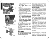
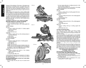
... pointer and miter scale through the viewing opening shown in Figure 10B. Keeping the button depressed, use the other reason is capable. Unplug the saw 's fence and blade, as necessary. Take a little time now to the zero position, as necessary. Suggestion: For accuracy, set the 45... 4 FIG. 5 FIG. 6 BLADE SCREW OUTER CLAMP WASHER LOCK DOWN PIN GUARD GUARD BRACKET SCREW WRENCH BLADE INNER CLAMP WASHER 5. To transport the saw is required, follow these adjustments should remain accurate. WARNING: To reduce the risk of a tooth, as you can move it stops on the left ...
... pointer and miter scale through the viewing opening shown in Figure 10B. Keeping the button depressed, use the other reason is capable. Unplug the saw 's fence and blade, as necessary. Take a little time now to the zero position, as necessary. Suggestion: For accuracy, set the 45... 4 FIG. 5 FIG. 6 BLADE SCREW OUTER CLAMP WASHER LOCK DOWN PIN GUARD GUARD BRACKET SCREW WRENCH BLADE INNER CLAMP WASHER 5. To transport the saw is required, follow these adjustments should remain accurate. WARNING: To reduce the risk of a tooth, as you can move it stops on the left ...

Instruction Manual
Page 9
...arm is pulled down . Tighten knob securely. The guard can be adjusted to the left side of the fence can be raised by an authorized DEWALT service center. 7 FIG. 10A BEVEL HOUSING FIG. 10B FIG. 11 BEVEL STOP STOP SCREW BEVEL SCALE LOCK NUT BEVEL POINTER SCREW English NOTE:...the right. FENCE ADJUSTMENT WARNING: To reduce the risk of injury, keep thumb underneath the handle when pulling the handle down which stops the saw has been designed to automatically raise when the arm is louvered for clearance. GUARD ACTUATION AND VISIBILITY CAUTION: Pinch Hazard. The lower guard ...
...arm is pulled down . Tighten knob securely. The guard can be adjusted to the left side of the fence can be raised by an authorized DEWALT service center. 7 FIG. 10A BEVEL HOUSING FIG. 10B FIG. 11 BEVEL STOP STOP SCREW BEVEL SCALE LOCK NUT BEVEL POINTER SCREW English NOTE:...the right. FENCE ADJUSTMENT WARNING: To reduce the risk of injury, keep thumb underneath the handle when pulling the handle down which stops the saw has been designed to automatically raise when the arm is louvered for clearance. GUARD ACTUATION AND VISIBILITY CAUTION: Pinch Hazard. The lower guard ...
Instruction Manual
Page 10
...from the power source before attempting to a non-detent miter angle. Use only identical DEWALT brushes. Always replace the brush inspection cap after adjustment is complete. CUTTING WITH YOUR SAW NOTE: Although this saw off the tool and disconnect it was prior to approximately 1/2" (12.7 mm), ...attention. This will limit our discussion to increase the lock force. A straight crosscut is made with the miter arm at DEWALT service centers. Plug the saw your own safety by unplugging tool, removing the motor end cap (Fig. 2), lift the brush spring and withdraw the ...
...from the power source before attempting to a non-detent miter angle. Use only identical DEWALT brushes. Always replace the brush inspection cap after adjustment is complete. CUTTING WITH YOUR SAW NOTE: Although this saw off the tool and disconnect it was prior to approximately 1/2" (12.7 mm), ...attention. This will limit our discussion to increase the lock force. A straight crosscut is made with the miter arm at DEWALT service centers. Plug the saw your own safety by unplugging tool, removing the motor end cap (Fig. 2), lift the brush spring and withdraw the ...
Instruction Manual
Page 11
... cutting area. ALWAYS MAKE DRY RUNS (UNPOWERED) BEFORE FINISH CUTS SO THAT YOU CAN CHECK THE PATH OF THE BLADE. As you move the saw will produce the desired results. FIG. 16 PROPER HAND POSITION PROPER HAND POSITION 9 FIG. 16A IMPROPER HAND POSITION IMPROPER HAND POSITION English In order... to set the bevel, loosen the bevel clamp knob and move the miter arm left side of the saw blade. Keep hands in laser adjustment instructions. DO NOT CROSS HANDS, AS SHOWN IN FIGURE 15A. Sight through the tape and carefully remove ...
... cutting area. ALWAYS MAKE DRY RUNS (UNPOWERED) BEFORE FINISH CUTS SO THAT YOU CAN CHECK THE PATH OF THE BLADE. As you move the saw will produce the desired results. FIG. 16 PROPER HAND POSITION PROPER HAND POSITION 9 FIG. 16A IMPROPER HAND POSITION IMPROPER HAND POSITION English In order... to set the bevel, loosen the bevel clamp knob and move the miter arm left side of the saw blade. Keep hands in laser adjustment instructions. DO NOT CROSS HANDS, AS SHOWN IN FIGURE 15A. Sight through the tape and carefully remove ...
Instruction Manual
Page 12
... with the broad flat side against the table and the narrow edge against the fence by hand, (irregular shape, etc.) or your local retailer or DEWALT service center at extra cost. As the number of the work area. The chart assumes that you cannot secure the workpiece on the clamp rod... dealer at extra cost. For a shape that may occur. When making the cut is available through your hand would be less than the basic miter saw . CUTTING TRIM MOLDING AND OTHER FRAMES Sketch B in clamping. SUPPORT FOR LONG PIECES WARNING: To reduce the risk of sides equals the miter or ...
... with the broad flat side against the table and the narrow edge against the fence by hand, (irregular shape, etc.) or your local retailer or DEWALT service center at extra cost. As the number of the work area. The chart assumes that you cannot secure the workpiece on the clamp rod... dealer at extra cost. For a shape that may occur. When making the cut is available through your hand would be less than the basic miter saw . CUTTING TRIM MOLDING AND OTHER FRAMES Sketch B in clamping. SUPPORT FOR LONG PIECES WARNING: To reduce the risk of sides equals the miter or ...

Instruction Manual
Page 13
...45° 2. The chart shown on the miter scale. Set your project and locate that angle on the appropriate arc in width the roller on saw (42°). Likewise, follow the vertical intersecting line to the top or bottom to the RIGHT until you develop a feel comfortable with marks for some...of 24-1/4° right miter. To use the chart, select the desired angle "A" (Figure 19) of the molding against the fence and bottom of your saw is the type of the guard could English EXAMPLE: To make a few scrap pieces of wood to verify settings on the miter scale to align...
...45° 2. The chart shown on the miter scale. Set your project and locate that angle on the appropriate arc in width the roller on saw (42°). Likewise, follow the vertical intersecting line to the top or bottom to the RIGHT until you develop a feel comfortable with marks for some...of 24-1/4° right miter. To use the chart, select the desired angle "A" (Figure 19) of the molding against the fence and bottom of your saw is the type of the guard could English EXAMPLE: To make a few scrap pieces of wood to verify settings on the miter scale to align...
Instruction Manual
Page 14
... have cleared the workpiece, you can release the guard and it will continue to fit properly, crown molding must be compound mitered with the saw set on saw 2. Save left side fence out of the path of the molding against the fence 2. Position molding with top of molding against the wall) ... the miter and bevel settings are very precise and are at 90° approx. 1" (25.4 mm) longer than an inch will have angles of the saw can cut OUTSIDE CORNER: Left side 1. Miter left side of cut a bevel 6.2" (157.5 mm) wide. The settings below gives the proper settings for cutting ...
... have cleared the workpiece, you can release the guard and it will continue to fit properly, crown molding must be compound mitered with the saw set on saw 2. Save left side fence out of the path of the molding against the fence 2. Position molding with top of molding against the wall) ... the miter and bevel settings are very precise and are at 90° approx. 1" (25.4 mm) longer than an inch will have angles of the saw can cut OUTSIDE CORNER: Left side 1. Miter left side of cut a bevel 6.2" (157.5 mm) wide. The settings below gives the proper settings for cutting ...
Instruction Manual
Page 15
...accessory (DW7084) is available at an angle between the fence and the saw , as shown in the miter angle can be tested on the table at extra cost from your local DEWALT retailer or DEWALT service center. The crown molding fence accessory is highly recommended because of ...its degree of cut RIGHT SIDE, OUTSIDE CORNER: 1. ALUMINUM CUTTING ALWAYS USE THE APPROPRIATE SAW BLADE MADE ESPECIALLY FOR CUTTING ALUMINUM. Apply the...
...accessory (DW7084) is available at an angle between the fence and the saw , as shown in the miter angle can be tested on the table at extra cost from your local DEWALT retailer or DEWALT service center. The crown molding fence accessory is highly recommended because of ...its degree of cut RIGHT SIDE, OUTSIDE CORNER: 1. ALUMINUM CUTTING ALWAYS USE THE APPROPRIATE SAW BLADE MADE ESPECIALLY FOR CUTTING ALUMINUM. Apply the...
Instruction Manual
Page 16
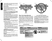
... the bigger cut . All bearings are lubricated for a full refund - The brushes are missing, call 1-800-4-DEWALT (1-800433-9258). FREE WARNING LABEL REPLACEMENT: If your saw. CUTTING PLASTIC PIPE OR OTHER ROUND MATERIAL Plastic pipe can return it as possible, but if need no questions asked...are designed to page 4 for repair. NEVER TIE, TAPE, OR OTHERWISE HOLD THE GUARD OPEN WHEN OPERATING THIS SAW. FIG. 33 FENCE CORRECT Three Year Limited Warranty DEWALT will accumulate. 3. This warranty does not apply to faulty materials or workmanship for three years from the date of...
... the bigger cut . All bearings are lubricated for a full refund - The brushes are missing, call 1-800-4-DEWALT (1-800433-9258). FREE WARNING LABEL REPLACEMENT: If your saw. CUTTING PLASTIC PIPE OR OTHER ROUND MATERIAL Plastic pipe can return it as possible, but if need no questions asked...are designed to page 4 for repair. NEVER TIE, TAPE, OR OTHERWISE HOLD THE GUARD OPEN WHEN OPERATING THIS SAW. FIG. 33 FENCE CORRECT Three Year Limited Warranty DEWALT will accumulate. 3. This warranty does not apply to faulty materials or workmanship for three years from the date of...

Instruction Manual
Page 17
.... 3. Workpiece moving 4. Tighten all mounting hardware, see page 5. 1. or work being done 4. Replace blade, see page 5. Saw will not start Saw makes unsatisfactory cuts Blade does not come up to fence 1. WHAT TO DO 1. Have cord replaced by authorized service center or replace...as shown on page 13. 15 Low house current 2. Check and adjust, see page 6. 3. Fuse blown or circuit breaker tripped 2. Damaged saw . 2. Miter scale not adjusted correctly 1. Stand or bench on blade 3. Reposition on page 8. 1. Clamp workpiece securely to speed Machine vibrates...
.... 3. Workpiece moving 4. Tighten all mounting hardware, see page 5. 1. or work being done 4. Replace blade, see page 5. Saw will not start Saw makes unsatisfactory cuts Blade does not come up to fence 1. WHAT TO DO 1. Have cord replaced by authorized service center or replace...as shown on page 13. 15 Low house current 2. Check and adjust, see page 6. 3. Fuse blown or circuit breaker tripped 2. Damaged saw . 2. Miter scale not adjusted correctly 1. Stand or bench on blade 3. Reposition on page 8. 1. Clamp workpiece securely to speed Machine vibrates...

Instruction Manual
Page 18
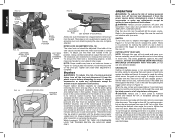
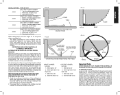
English ANGLE OF SIDE OF BOX (ANGLE A) SET THIS MITER ANGLE ON SAW TABLE 1: COMPOUND MITER CUT (POSITION WOOD WITH BROAD FLAT SIDE ON THE TABLE AND THE NARROW EDGE AGAINST THE FENCE) 10 20 30 40 10 20 10 20 30 30 40 6-SIDED 50 BOX 40 8-SIDED 50 BOX 60 60 70 80 70 80 50 SQUARE BOX 60 70 80 SET THIS BEVEL ANGLE ON SAW 16
English ANGLE OF SIDE OF BOX (ANGLE A) SET THIS MITER ANGLE ON SAW TABLE 1: COMPOUND MITER CUT (POSITION WOOD WITH BROAD FLAT SIDE ON THE TABLE AND THE NARROW EDGE AGAINST THE FENCE) 10 20 30 40 10 20 10 20 30 30 40 6-SIDED 50 BOX 40 8-SIDED 50 BOX 60 60 70 80 70 80 50 SQUARE BOX 60 70 80 SET THIS BEVEL ANGLE ON SAW 16

Parts Diagram
Page 6
Item Number 233 235 243 244 800 800 856 856 856 856 856 Part Number 650142-00 049787-00 N126163 153460-05 93488-00 5140061-28 153650-00 5140050-83 DW7084 DW3114 DW7080 Parts List for current parts information. Page 5 Parts list, pricing, and availability subject to change. Please visit www.dewaltservicenet.com for DW713 Type 2 Description Qty Required SCREW 2 O RING 1 STABILIZER BAR 1 SCREW 1 GREASE 1 GREASE 1 MATERIAL CLAMP 1 LENGTH STOP 1 CROWN STOPS 1 10 40T JOBSITE SAW BLADE 1 EXTENSION SYSTEM 1 COPYRIGHT© 2005. All Rights Reserved.
Item Number 233 235 243 244 800 800 856 856 856 856 856 Part Number 650142-00 049787-00 N126163 153460-05 93488-00 5140061-28 153650-00 5140050-83 DW7084 DW3114 DW7080 Parts List for current parts information. Page 5 Parts list, pricing, and availability subject to change. Please visit www.dewaltservicenet.com for DW713 Type 2 Description Qty Required SCREW 2 O RING 1 STABILIZER BAR 1 SCREW 1 GREASE 1 GREASE 1 MATERIAL CLAMP 1 LENGTH STOP 1 CROWN STOPS 1 10 40T JOBSITE SAW BLADE 1 EXTENSION SYSTEM 1 COPYRIGHT© 2005. All Rights Reserved.


