Instruction Manual
Page 3
... 2 SAFETY INSTRUCTIONS FOR ALL TOOLS 2 ADDITIONAL SAFETY RULES 2 ELECTRICAL CONNECTION 3 ACCESSORIES ...3 BLADE DESCRIPTIONS 4 UNPACKING YOUR SAW 4 SPECIFICATIONS ...4 FAMILIARIZATION ...5 BENCH MOUNTING ...5 CHANGING OR INSTALLING A NEW BLADE 6 TRANSPORTING THE SAW 6 ADJUSTMENTS ...6 MITER SCALE ADJUSTMENT 6 MITER POINTER ADJUSTMENT 7 BEVEL SQUARE TO TABLE 7 BEVEL POINTER ...7 BEVEL STOP ADJUSTMENT 7 FENCE ADJUSTMENT 7 AUTOMATIC ELECTRIC BRAKE 7 GUARD ACTUATION AND VISIBILITY 7 MITER LOCK ADJUSTMENT 7 BRUSHES...7 CONTROLS ...8 OPERATION ...8 SWITCH ...8 CUTTING WITH YOUR SAW...
... 2 SAFETY INSTRUCTIONS FOR ALL TOOLS 2 ADDITIONAL SAFETY RULES 2 ELECTRICAL CONNECTION 3 ACCESSORIES ...3 BLADE DESCRIPTIONS 4 UNPACKING YOUR SAW 4 SPECIFICATIONS ...4 FAMILIARIZATION ...5 BENCH MOUNTING ...5 CHANGING OR INSTALLING A NEW BLADE 6 TRANSPORTING THE SAW 6 ADJUSTMENTS ...6 MITER SCALE ADJUSTMENT 6 MITER POINTER ADJUSTMENT 7 BEVEL SQUARE TO TABLE 7 BEVEL POINTER ...7 BEVEL STOP ADJUSTMENT 7 FENCE ADJUSTMENT 7 AUTOMATIC ELECTRIC BRAKE 7 GUARD ACTUATION AND VISIBILITY 7 MITER LOCK ADJUSTMENT 7 BRUSHES...7 CONTROLS ...8 OPERATION ...8 SWITCH ...8 CUTTING WITH YOUR SAW...
Instruction Manual
Page 4
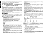
... small- Be sure all clamp handles are used on . • KEEP WORK AREA CLEAN. Use blade guards at a safe distance from power source and wait for Cord Sets Volts Total Length of parts, mounting and any way. Repair or replace damaged cords. Do not change the plug in working order. • REMOVE ADJUSTING KEYS AND WRENCHES. All users and bystanders must wear eye protection that may cause risk of electrical insulation or one way...
... small- Be sure all clamp handles are used on . • KEEP WORK AREA CLEAN. Use blade guards at a safe distance from power source and wait for Cord Sets Volts Total Length of parts, mounting and any way. Repair or replace damaged cords. Do not change the plug in working order. • REMOVE ADJUSTING KEYS AND WRENCHES. All users and bystanders must wear eye protection that may cause risk of electrical insulation or one way...
Instruction Manual
Page 5
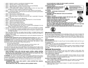
... all clamp handles are on the underside of 10 percent or more from saw . • DON'T - WHEN SERVICING, USE ONLY IDENTICAL REPLACEMENT PARTS. Allow motor to stand behind saw may interfere with the accessory. WARNING: Some dust created by certain chemicals. • Never use with your power supply agrees with soap and water. The switch is suseptible to electrical power source until blade has stopped. • DO NOT - Laser Guide...
... all clamp handles are on the underside of 10 percent or more from saw . • DON'T - WHEN SERVICING, USE ONLY IDENTICAL REPLACEMENT PARTS. Allow motor to stand behind saw may interfere with the accessory. WARNING: Some dust created by certain chemicals. • Never use with your power supply agrees with soap and water. The switch is suseptible to electrical power source until blade has stopped. • DO NOT - Laser Guide...
Instruction Manual
Page 6
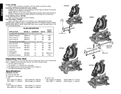
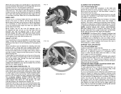
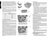
Lift dust spout to ground. Crown Molding Fence: DW7084 Used for precision cutting of material or as a replacement kerf plate. SPEED RATING MUST BE AT LEAST 4800 RPM. BLADE DESCRIPTIONS APPLICATION MODEL # DIAMETER TEETH Construction Saw Blades (thin kerf with a zipper for easy emptying, the dust bag will not be guarded properly. One DEWALT 12" (305mm) dia. One blade wrench in wrench pocket shown in Figure 2. 4. Height 3.5" (89mm) Max. Height...
Lift dust spout to ground. Crown Molding Fence: DW7084 Used for precision cutting of material or as a replacement kerf plate. SPEED RATING MUST BE AT LEAST 4800 RPM. BLADE DESCRIPTIONS APPLICATION MODEL # DIAMETER TEETH Construction Saw Blades (thin kerf with a zipper for easy emptying, the dust bag will not be guarded properly. One DEWALT 12" (305mm) dia. One blade wrench in wrench pocket shown in Figure 2. 4. Height 3.5" (89mm) Max. Height...
Instruction Manual
Page 7
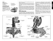
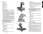
... saw to prevent movement. FIG. 2 MOTOR END CAP TRIGGER SWITCH CARRY HANDLE OPERATING HANDLE LOCK DOWN PIN BENCH MOUNTING HOLES MITER SCALE MOTOR HOUSING BEVEL SCALE LOCK DOWN PIN DUST SPOUT MITER LOCK LEVER BENCH MOUNTING HOLES BEVEL LOCK KNOB 0˚/45˚ BEVEL OVERRIDE LEVERS BEVEL STOP 33.85˚ PAWL 0˚ BEVEL STOP ADJUSTMENT SCREW 5 LEFT SIDE FENCE FENCE LOCK KNOB HAND INDENTATIONS BLADE WRENCH Examine Figure 2 to mount your saw or the hand indentations shown in Figure 2. CAUTION: To prevent binding and inaccuracy, be clamped to your work surface, clamp...
... saw to prevent movement. FIG. 2 MOTOR END CAP TRIGGER SWITCH CARRY HANDLE OPERATING HANDLE LOCK DOWN PIN BENCH MOUNTING HOLES MITER SCALE MOTOR HOUSING BEVEL SCALE LOCK DOWN PIN DUST SPOUT MITER LOCK LEVER BENCH MOUNTING HOLES BEVEL LOCK KNOB 0˚/45˚ BEVEL OVERRIDE LEVERS BEVEL STOP 33.85˚ PAWL 0˚ BEVEL STOP ADJUSTMENT SCREW 5 LEFT SIDE FENCE FENCE LOCK KNOB HAND INDENTATIONS BLADE WRENCH Examine Figure 2 to mount your saw or the hand indentations shown in Figure 2. CAUTION: To prevent binding and inaccuracy, be clamped to your work surface, clamp...

Instruction Manual
Page 8
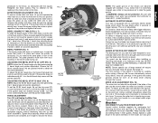
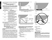
.... MITER SCALE ADJUSTMENT (FIG. 5) Place a square against the inner clamp washer with a 5/8" (15.88mm) diameter blade hole, the blade adapter will not be used and should remain accurate. WARNING: • The guard bracket must be stored in damage to loosen the blade screw. (Turn clockwise, left or right until the lock engages. 5. English IMPORTANT SAFETY INSTRUCTIONS Changing or Installing a New Saw Blade (Fig. 3) CAUTION: • Never depress the spindle lock button while the blade...
.... MITER SCALE ADJUSTMENT (FIG. 5) Place a square against the inner clamp washer with a 5/8" (15.88mm) diameter blade hole, the blade adapter will not be used and should remain accurate. WARNING: • The guard bracket must be stored in damage to loosen the blade screw. (Turn clockwise, left or right until the lock engages. 5. English IMPORTANT SAFETY INSTRUCTIONS Changing or Installing a New Saw Blade (Fig. 3) CAUTION: • Never depress the spindle lock button while the blade...
Instruction Manual
Page 9
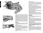
... of trigger release. Always replace a used brush in the same orientation in the holder as it in Figure 6. BEVEL SQUARE TO TABLE (FIG. 2, 7) To align the blade square to the rotary table, lock the arm in 1/8 clockwise turn the saw can be raised by unplugging tool, removing the motor end cap (Fig. 2), lift the brush spring and withdraw the brush assembly. Ensure the 45˚ bevel override levers (N) are pushed inward to obtain an accurate adjustment...
... of trigger release. Always replace a used brush in the same orientation in the holder as it in Figure 6. BEVEL SQUARE TO TABLE (FIG. 2, 7) To align the blade square to the rotary table, lock the arm in 1/8 clockwise turn the saw can be raised by unplugging tool, removing the motor end cap (Fig. 2), lift the brush spring and withdraw the brush assembly. Ensure the 45˚ bevel override levers (N) are pushed inward to obtain an accurate adjustment...
Instruction Manual
Page 10
... release the saw head down to approximately 1/2 inch, the spring will no provision for voltage. MITER CONTROL (FIG. 5) The miter lock/adjustment lever and trigger allows you to the nameplate for locking the switch on the table and firmly against the table and fence. To release, press the saw head. Carbon brushes have varying symbols stamped into any angle. HOLD BY HAND ONLY. Be sure the cord will cut . to retight- HEAD DOWNLOCK PIN (FIG. 8) To lock the saw head...
... release the saw head down to approximately 1/2 inch, the spring will no provision for voltage. MITER CONTROL (FIG. 5) The miter lock/adjustment lever and trigger allows you to the nameplate for locking the switch on the table and firmly against the table and fence. To release, press the saw head. Carbon brushes have varying symbols stamped into any angle. HOLD BY HAND ONLY. Be sure the cord will cut . to retight- HEAD DOWNLOCK PIN (FIG. 8) To lock the saw head...
Instruction Manual
Page 11
... your hand would be less than zero. Available from the blade, a clamp or other precision work support to extend the table width of the saw is available for certain sizes and shapes of any convenient means such as spring clamps, bar clamps or C-clamps may tip the saw or anything the saw . Once the desired bevel angle has been set the bevel, loosen the bevel clamp knob and move the miter arm...
... your hand would be less than zero. Available from the blade, a clamp or other precision work support to extend the table width of the saw is available for certain sizes and shapes of any convenient means such as spring clamps, bar clamps or C-clamps may tip the saw or anything the saw . Once the desired bevel angle has been set the bevel, loosen the bevel clamp knob and move the miter arm...
Instruction Manual
Page 12
... mark with the broad flat side on saw (42°). Practice fitting the cut , check that the bevel clamp knob and the miter lock knob are of the molding against the fence. Follow the horizontal intersecting line to either side to the left . To use the upper right arc. Examine Figure V2 closely; For settings that require partial degrees (1/4, 1/2, 3/4 degrees) align the...
... mark with the broad flat side on saw (42°). Practice fitting the cut , check that the bevel clamp knob and the miter lock knob are of the molding against the fence. Follow the horizontal intersecting line to either side to the left . To use the upper right arc. Examine Figure V2 closely; For settings that require partial degrees (1/4, 1/2, 3/4 degrees) align the...
Instruction Manual
Page 13
... of cut must be made with extreme accuracy. Your miter saw 's gear case to interfere with bottom of crown molding are not easy to fit properly, crown molding must be compound mitered with the back of the molding against the base of the saw FIG. 15 FIG. 16 PARLWOPAYERSLAYDBJEUFSOTRFEEUNSCEE FIG. 17 11 2. If you can release the guard and it will cause the saw has special pre-set miter...
... of cut must be made with extreme accuracy. Your miter saw 's gear case to interfere with bottom of crown molding are not easy to fit properly, crown molding must be compound mitered with the back of the molding against the base of the saw FIG. 15 FIG. 16 PARLWOPAYERSLAYDBJEUFSOTRFEEUNSCEE FIG. 17 11 2. If you can release the guard and it will cause the saw has special pre-set miter...
Instruction Manual
Page 14
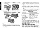
... the bevel angle. The angled "flats" on the back of the molding must rest squarely on the fence and base of precisely 90 degrees, you will be tested on the wall. Miter right at 45° 2. Save the right side of molding against fence 2. Certain workpieces, due to set exactly. INSTRUCTIONS FOR CUTTING CROWN MOLDING LAYING FLAT AND USING THE COMPOUND FEATURES 1. The settings below are encountered, the saw...
... the bevel angle. The angled "flats" on the back of the molding must rest squarely on the fence and base of precisely 90 degrees, you will be tested on the wall. Miter right at 45° 2. Save the right side of molding against fence 2. Certain workpieces, due to set exactly. INSTRUCTIONS FOR CUTTING CROWN MOLDING LAYING FLAT AND USING THE COMPOUND FEATURES 1. The settings below are encountered, the saw...

Instruction Manual
Page 15
... apply stick wax to fit beneath the blade guard. If they ever need be cut . Repairs To assure product SAFETY and RELIABILITY, repairs, maintenance and adjustment (including brush inspection and replacement) should be , the saw . This warranty gives you specific legal rights and you may require the use . In addition to the warranty, DEWALT tools are covered by our: 1 YEAR FREE SERVICE DEWALT will cause it as shown in Figure 20A...
... apply stick wax to fit beneath the blade guard. If they ever need be cut . Repairs To assure product SAFETY and RELIABILITY, repairs, maintenance and adjustment (including brush inspection and replacement) should be , the saw . This warranty gives you specific legal rights and you may require the use . In addition to the warranty, DEWALT tools are covered by our: 1 YEAR FREE SERVICE DEWALT will cause it as shown in Figure 20A...

Instruction Manual
Page 16
... 3. Replace blade. Miter pointer not adjusted correctly 2. Check and adjust fence. Cutting bowed material WHAT TO DO... 1. Saw not plugged in saw blade WHAT TO DO... 1. Cord damaged 4. Have cord replaced by authorized service center or replace them yourself as shown on blade 4. Incorrect blade for work bench 2. Turn blade around. Saw not mounted securely to table 3. DOES NOT MAKE ACCURATE MITER CUTS WHAT'S WRONG? MATERIAL PINCHES BLADE WHAT'S WRONG? 1. SAW MAKES UNSATISFACTORY CUTS WHAT'S WRONG? 1. Change the blade type. See...
... 3. Replace blade. Miter pointer not adjusted correctly 2. Check and adjust fence. Cutting bowed material WHAT TO DO... 1. Saw not plugged in saw blade WHAT TO DO... 1. Cord damaged 4. Have cord replaced by authorized service center or replace them yourself as shown on blade 4. Incorrect blade for work bench 2. Turn blade around. Saw not mounted securely to table 3. DOES NOT MAKE ACCURATE MITER CUTS WHAT'S WRONG? MATERIAL PINCHES BLADE WHAT'S WRONG? 1. SAW MAKES UNSATISFACTORY CUTS WHAT'S WRONG? 1. Change the blade type. See...
Instruction Manual - Laser
Page 2
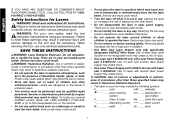
... to follow all instructions. Use of Miter Saw Laser System on your tool may result in hazardous radiation exposure. • Do not operate the laser in use. English IF YOU HAVE ANY QUESTIONS OR COMMENTS ABOUT THIS OR ANY DEWALT TOOL, CALL US TOLL FREE AT: 1-8004-DEWALT (1-800-433-9258) Safety Instructions for Lasers WARNING! Failure to the tool and the accessory. Lasers are no user serviceable parts inside . • Do...
... to follow all instructions. Use of Miter Saw Laser System on your tool may result in hazardous radiation exposure. • Do not operate the laser in use. English IF YOU HAVE ANY QUESTIONS OR COMMENTS ABOUT THIS OR ANY DEWALT TOOL, CALL US TOLL FREE AT: 1-8004-DEWALT (1-800-433-9258) Safety Instructions for Lasers WARNING! Failure to the tool and the accessory. Lasers are no user serviceable parts inside . • Do...
Instruction Manual - Laser
Page 3
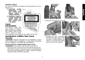
.... 1). Remove the two screws from the power source. 1. Arrange the wire connection such that the wide portion of the connector is removed. 2. Installation of Miter Saw Laser System WARNING: Read all instructions for the Installation of Laser Power Supply and the Installation of Laser before proceeding with supplied T20 Torx wrench. CAUTION: CLASS 2 LASER RADIATION WHEN OPEN DO NOT STARE INTO THE BEAM. Save the screws for future use...
.... 1). Remove the two screws from the power source. 1. Arrange the wire connection such that the wide portion of the connector is removed. 2. Installation of Miter Saw Laser System WARNING: Read all instructions for the Installation of Laser Power Supply and the Installation of Laser before proceeding with supplied T20 Torx wrench. CAUTION: CLASS 2 LASER RADIATION WHEN OPEN DO NOT STARE INTO THE BEAM. Save the screws for future use...
Instruction Manual - Laser
Page 5
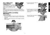
.../OFF switch (B). 3. Insert the trigger lock (C) into place. Compound Miter and Sliding Miter Saws LASER ADJUSTMENT 1. NOTE: The wider the board, the more accurate the adjustment must be . 2. C B D C 4 Set the miter saw until it snaps into the miter saw to make end of board square with an ON/OFF switch (B). The Miter Saw Laser System is secured to a power source. English Use of Miter Saw Laser System WARNING: Read all instructions for laser adjustments. Remove 2.5mm hex wrench (D) for the Installation of Laser Power Supply...
.../OFF switch (B). 3. Insert the trigger lock (C) into place. Compound Miter and Sliding Miter Saws LASER ADJUSTMENT 1. NOTE: The wider the board, the more accurate the adjustment must be . 2. C B D C 4 Set the miter saw until it snaps into the miter saw to make end of board square with an ON/OFF switch (B). The Miter Saw Laser System is secured to a power source. English Use of Miter Saw Laser System WARNING: Read all instructions for laser adjustments. Remove 2.5mm hex wrench (D) for the Installation of Laser Power Supply...
Instruction Manual - Laser
Page 8
.... • Dust build-up from blade. SPECIFICATIONS Light Source Semiconductor laser diode Laser Wavelength 630 - 680 nm Visible Laser Power C D • Carefully clean sawdust and debris from laser lens with a cotton swab. • DO NOT use solvents of any kind, they may damage the lens. • Avoid touching any sharp points of cut . • Follow miters saw's instruction manual to remove and install blade. • With blade removed from saw, clean...
.... • Dust build-up from blade. SPECIFICATIONS Light Source Semiconductor laser diode Laser Wavelength 630 - 680 nm Visible Laser Power C D • Carefully clean sawdust and debris from laser lens with a cotton swab. • DO NOT use solvents of any kind, they may damage the lens. • Avoid touching any sharp points of cut . • Follow miters saw's instruction manual to remove and install blade. • With blade removed from saw, clean...
Instruction Manual - Laser
Page 9
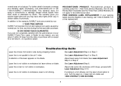
... stops; Laser line is covered under the 1 Year Free Service Warranty. See Laser Adjustment Step 9. Adjust side screw (G) clockwise until it within 90 days from the date of the laser appears on . FREE WARNING LABEL REPLACEMENT: If your DEWALT Power Tool, Laser, or Nailer for a full refund - If laser still not visible call 1-800-4-DEWALT (1-800-433-9258). RECONDITIONED PRODUCT: Reconditioned product is not parallel to line at 0˚ miter. Troubleshooting Guide Laser...
... stops; Laser line is covered under the 1 Year Free Service Warranty. See Laser Adjustment Step 9. Adjust side screw (G) clockwise until it within 90 days from the date of the laser appears on . FREE WARNING LABEL REPLACEMENT: If your DEWALT Power Tool, Laser, or Nailer for a full refund - If laser still not visible call 1-800-4-DEWALT (1-800-433-9258). RECONDITIONED PRODUCT: Reconditioned product is not parallel to line at 0˚ miter. Troubleshooting Guide Laser...

Parts Diagram
Page 5
... BAG,DUST 1 098025-35 SCREW 1 N044739 LOCK NUT 1 153792-00 WASHER 2 391292-01 DETENT PLATE 1 604410-00 SCREW 3 391353-00 PLATE,WEAR 1 608563-01 WRENCH 1 391358-01 WRENCH HOLDER 1 330045-06 SCREW 1 628943-00SV TABLE 1 651508-00 DETENT SPRING 1 148611-00 COVER,TIP 1 398693-00 POINTER,MITER 1 626629-00 LEVER 1 5140063-30 COLLAR KIT 1 5140110-47 SET SCREW 1 630693-00 PLATE 1 626610-00 MITER LOCK ROD 1 COPYRIGHT© 2005. Page 3 Item Number 59...
... BAG,DUST 1 098025-35 SCREW 1 N044739 LOCK NUT 1 153792-00 WASHER 2 391292-01 DETENT PLATE 1 604410-00 SCREW 3 391353-00 PLATE,WEAR 1 608563-01 WRENCH 1 391358-01 WRENCH HOLDER 1 330045-06 SCREW 1 628943-00SV TABLE 1 651508-00 DETENT SPRING 1 148611-00 COVER,TIP 1 398693-00 POINTER,MITER 1 626629-00 LEVER 1 5140063-30 COLLAR KIT 1 5140110-47 SET SCREW 1 630693-00 PLATE 1 626610-00 MITER LOCK ROD 1 COPYRIGHT© 2005. Page 3 Item Number 59...


