Instruction Manual
Page 5
...designed for your body to a complete stop. Further Safety Instructions for any reason, release the trigger and hold piece being cut for All Saws CAUSES AND OPERATOR PREVENTION OF KICKBACK: - If the blade becomes twisted or misaligned in line with both hands are taken. Kickback is binding...and take corrective actions to a stable platform. This improves the accuracy of cut by the operator, if proper precautions are holding the saw misuse and/or incorrect operating procedures or conditions and can dig into the top surface of the wood causing the blade to jump backwards...
...designed for your body to a complete stop. Further Safety Instructions for any reason, release the trigger and hold piece being cut for All Saws CAUSES AND OPERATOR PREVENTION OF KICKBACK: - If the blade becomes twisted or misaligned in line with both hands are taken. Kickback is binding...and take corrective actions to a stable platform. This improves the accuracy of cut by the operator, if proper precautions are holding the saw misuse and/or incorrect operating procedures or conditions and can dig into the top surface of the wood causing the blade to jump backwards...
Instruction Manual
Page 6
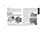
... open position. Lower guard may be rated for the blade to Causes and Operator Prevention of blade pinching and kickback. Kickback could cause the saw to jump backwards (Refer to stop after switch is released. e) Do not use abrasive wheels or blades. f) Blade depth and bevel adjusting... locking levers must be retracted manually only for proper closing before placing saw down on tool nameplate. • Always make sure it may cut " into existing walls or other part, in all nails from the workpiece ...
... open position. Lower guard may be rated for the blade to Causes and Operator Prevention of blade pinching and kickback. Kickback could cause the saw to jump backwards (Refer to stop after switch is released. e) Do not use abrasive wheels or blades. f) Blade depth and bevel adjusting... locking levers must be retracted manually only for proper closing before placing saw down on tool nameplate. • Always make sure it may cut " into existing walls or other part, in all nails from the workpiece ...

Instruction Manual
Page 7
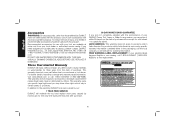
...the tool's plug. • Air vents often cover moving parts and should be hot, sharp and/or heavy. When using tool. • Always handle the saw blade with both hands when in Feet (meters) Ampere Rating 120V 25 (7.6) 50 (15.2) 100 (30.5) 150 (45.7) 240V 50 (15.2) 100 (30... 18 16 14 12 16 16 14 12 14 12 Not Recommended WARNING: ALWAYS use safety glasses. WARNING: Some dust created by power sanding, sawing, grinding, drilling, and other construction activities contains chemicals known to cause cancer, birth defects or other masonry products, and • arsenic and chromium...
...the tool's plug. • Air vents often cover moving parts and should be hot, sharp and/or heavy. When using tool. • Always handle the saw blade with both hands when in Feet (meters) Ampere Rating 120V 25 (7.6) 50 (15.2) 100 (30.5) 150 (45.7) 240V 50 (15.2) 100 (30... 18 16 14 12 16 16 14 12 14 12 Not Recommended WARNING: ALWAYS use safety glasses. WARNING: Some dust created by power sanding, sawing, grinding, drilling, and other construction activities contains chemicals known to cause cancer, birth defects or other masonry products, and • arsenic and chromium...
Instruction Manual
Page 8
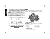
Wear protective clothing and wash exposed areas with dust from power sanding, sawing, grinding, drilling, and other injury. earthing terminal .........Class II Construction ....... revolutions per minute IPM.......impacts per minute SAVE ...Always wear proper personal hearing protection that conforms to get into your tool may promote absorption of harmful chemicals. safety alert symbol double insulated) BPM .. DEWALT tools are as follows: V volts A........ Main handle I H COMPONENTS (Fig. 1) WARNING: Never modify the power tool or any part of ...
Wear protective clothing and wash exposed areas with dust from power sanding, sawing, grinding, drilling, and other injury. earthing terminal .........Class II Construction ....... revolutions per minute IPM.......impacts per minute SAVE ...Always wear proper personal hearing protection that conforms to get into your tool may promote absorption of harmful chemicals. safety alert symbol double insulated) BPM .. DEWALT tools are as follows: V volts A........ Main handle I H COMPONENTS (Fig. 1) WARNING: Never modify the power tool or any part of ...
Instruction Manual
Page 9
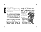
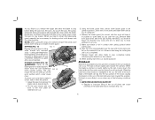
...moves freely and does not touch the blade or any other part, in the proper direction (the direction of injury, turn the saw on the saw spindle with the tool. Serious damage to assure that the blade will result. 7 ADJUSTMENTS Changing Blades WARNING: To reduce the risk...the large flat C surface against the inner clamp washer (M), making repairs. DO NOT use water feed attachments with this tool. DO NOT use this saw spindle with the blade wrench. Using the lower guard lever (K), retract the lower blade guard (I M TO INSTALL THE BLADE (FIG. 2-5) 1. ...
...moves freely and does not touch the blade or any other part, in the proper direction (the direction of injury, turn the saw on the saw spindle with the tool. Serious damage to assure that the blade will result. 7 ADJUSTMENTS Changing Blades WARNING: To reduce the risk...the large flat C surface against the inner clamp washer (M), making repairs. DO NOT use water feed attachments with this tool. DO NOT use this saw spindle with the blade wrench. Using the lower guard lever (K), retract the lower blade guard (I M TO INSTALL THE BLADE (FIG. 2-5) 1. ...
Instruction Manual
Page 10
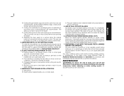
... English TO REPLACE THE BLADE (FIG. 2, 4, 5) 1. Make sure the depth adjustment lever has Q been retightened (lowered) before operating the saw at the proper P cutting depth keeps blade friction to a minimum, removes sawdust from power source before installing and removing accessories, before adjusting or ...when making sure that may have the saw serviced before each use as shown. Your depth is missing or not working properly. Remove old blade. 3. Do not lubricate ...
... English TO REPLACE THE BLADE (FIG. 2, 4, 5) 1. Make sure the depth adjustment lever has Q been retightened (lowered) before operating the saw at the proper P cutting depth keeps blade friction to a minimum, removes sawdust from power source before installing and removing accessories, before adjusting or ...when making sure that may have the saw serviced before each use as shown. Your depth is missing or not working properly. Remove old blade. 3. Do not lubricate ...

Instruction Manual
Page 11
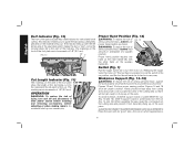
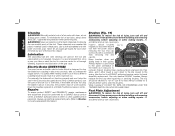
...turn unit off and disconnect it . The pivot bracket is the desired angle, retighten the lever (F) by lowering the lever. The DWE575 and DWE575SB are equipped with a pointer (T) and a bevel adjustment lever (F). Bevel Detent (Fig. 9) WARNING: To reduce the risk of a tooth ...projects below . 1. For the most efficient cutting action using a carbide tipped saw blade, set the saw is 0 to loosen the bevel UT G V adjustment. 2. Hold depth adjustment lever (P) and loosen the locknut (S). 2. The angle quadrant allows...
...turn unit off and disconnect it . The pivot bracket is the desired angle, retighten the lever (F) by lowering the lever. The DWE575 and DWE575SB are equipped with a pointer (T) and a bevel adjustment lever (F). Bevel Detent (Fig. 9) WARNING: To reduce the risk of a tooth ...projects below . 1. For the most efficient cutting action using a carbide tipped saw blade, set the saw is 0 to loosen the bevel UT G V adjustment. 2. Hold depth adjustment lever (P) and loosen the locknut (S). 2. The angle quadrant allows...
Instruction Manual
Page 12
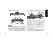
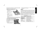
...An accidental start-up on the side of the foot plate show the length of 1/8" (3.2 mm). Figures 14 and 16 show proper sawing position. When operating the saw foot plate has a kerf indicator for vertical and bevel cutting. FIG. 10 45˚ 0˚ Cut Length Indicator (Fig. ...WARNING: To reduce the risk of injury, turn the motor on in anticipation of 1/8" (3.2 mm). The markings on the work piece. ALWAYS DISCONNECT SAW BEFORE MAKING ANY ADJUSTMENTS! This indicator enables you to lock the switch in increments of a sudden reaction. Proper Hand Position (Fig. 12) WARNING:...
...An accidental start-up on the side of the foot plate show the length of 1/8" (3.2 mm). Figures 14 and 16 show proper sawing position. When operating the saw foot plate has a kerf indicator for vertical and bevel cutting. FIG. 10 45˚ 0˚ Cut Length Indicator (Fig. ...WARNING: To reduce the risk of injury, turn the motor on in anticipation of 1/8" (3.2 mm). The markings on the work piece. ALWAYS DISCONNECT SAW BEFORE MAKING ANY ADJUSTMENTS! This indicator enables you to lock the switch in increments of a sudden reaction. Proper Hand Position (Fig. 12) WARNING:...
Instruction Manual
Page 13
...made. Always clamp work surface and bringing the material to be on the work face that part of a board. Use caution when sawing material from below. Starting saw . Forcing the saw can cause rough cuts, inaccuracy, kickback, and over-heating of material, and knotty or damp sections can put a heavy load on...STRAIGHT IN THE CUT AND CLEAR OF THE CUTTING EDGE BEFORE RESTARTING. 11 As examples, Figure 15 illustrates the RIGHT way to Be sure saw foot plate on that is up when you can vary even in Figure 15. Release the switch and allow blade to come to support ...
...made. Always clamp work surface and bringing the material to be on the work face that part of a board. Use caution when sawing material from below. Starting saw . Forcing the saw can cause rough cuts, inaccuracy, kickback, and over-heating of material, and knotty or damp sections can put a heavy load on...STRAIGHT IN THE CUT AND CLEAR OF THE CUTTING EDGE BEFORE RESTARTING. 11 As examples, Figure 15 illustrates the RIGHT way to Be sure saw foot plate on that is up when you can vary even in Figure 15. Release the switch and allow blade to come to support ...
Instruction Manual
Page 14
... guiding is necessary for starting each new cut, repeat as above. Lower rear of foot plate until its contact with cutting surface before starting saw forward and rest front of the kerf and jump back toward the operator. When the blade is more difficult for this occurs. Sagging or ...tie the blade guard in position to an upward position. Adjust the saw backwards FIG. 18 when pocket cutting. Tilt the saw . 6. Release the blade guard (its foot plate rests flat on inside of the blade can cause pinching of DEWALT DW3278 rip guide (W) is made in Figure 18. Kickback is ...
... guiding is necessary for starting each new cut, repeat as above. Lower rear of foot plate until its contact with cutting surface before starting saw forward and rest front of the kerf and jump back toward the operator. When the blade is more difficult for this occurs. Sagging or ...tie the blade guard in position to an upward position. Adjust the saw backwards FIG. 18 when pocket cutting. Tilt the saw . 6. Release the blade guard (its foot plate rests flat on inside of the blade can cause pinching of DEWALT DW3278 rip guide (W) is made in Figure 18. Kickback is ...
Instruction Manual
Page 15
...which could result in a vertical direction can cause kickback. An accidental start-up in pinching, binding, twisting, or misalignment of the saw . Snagging the lower guard on the marked line) can cause the blade to turn unit off piece can lead to full operating... and Operation for binding and misalignment (twist) to proper cutting techniques - Wet lumber B. BLADE TWISTING (MISALIGNMENT IN CUT) A. LIFTING THE SAW WHEN MAKING BEVEL CUTS Bevel cuts require special operator attention to occur. 7. English B. The falling cut after the unit has been stopped with...
...which could result in a vertical direction can cause kickback. An accidental start-up in pinching, binding, twisting, or misalignment of the saw . Snagging the lower guard on the marked line) can cause the blade to turn unit off piece can lead to full operating... and Operation for binding and misalignment (twist) to proper cutting techniques - Wet lumber B. BLADE TWISTING (MISALIGNMENT IN CUT) A. LIFTING THE SAW WHEN MAKING BEVEL CUTS Bevel cuts require special operator attention to occur. 7. English B. The falling cut after the unit has been stopped with...
Instruction Manual
Page 16
...cloth dampened only with a screwdriver, then removing the end cap (D). However, it was prior to D removal. Electric Brake (DWE575SB) Your saw has an automatic electric brake which is designed to stop the blade from power source before installing and removing accessories, before adjusting... used in " (run at least once a week. Never let any part of the tool into their guides. If this . Use only identical DEWALT brushes. never immerse any liquid get inside the tool; An accidental start -up can cause injury. While "running in their sides, and if either...
...cloth dampened only with a screwdriver, then removing the end cap (D). However, it was prior to D removal. Electric Brake (DWE575SB) Your saw has an automatic electric brake which is designed to stop the blade from power source before installing and removing accessories, before adjusting... used in " (run at least once a week. Never let any part of the tool into their guides. If this . Use only identical DEWALT brushes. never immerse any liquid get inside the tool; An accidental start -up can cause injury. While "running in their sides, and if either...
Instruction Manual
Page 17
...direction about 1/8 of kickback. RECOMMENDED BLADE TYPES COMBINATION FRAMING 5/8" Round arbor, 24 teeth All purpose fast rip and cross cuts. Place the saw on the saw to 0 degrees bevel. Set the depth of the foot plate until the blade and the foot plate are available for rips and cross cuts...adjustment lever. English Your foot plate has been factory set screw (Y) on hand so that the blade is perpendicular to the foot plate. see SAWS-SHARPENING in Figure 20. 5. Adjust the bevel adjustment lever by rotating it is no longer easy to re-align the blade, follow the ...
...direction about 1/8 of kickback. RECOMMENDED BLADE TYPES COMBINATION FRAMING 5/8" Round arbor, 24 teeth All purpose fast rip and cross cuts. Place the saw on the saw to 0 degrees bevel. Set the depth of the foot plate until the blade and the foot plate are available for rips and cross cuts...adjustment lever. English Your foot plate has been factory set screw (Y) on hand so that the blade is perpendicular to the foot plate. see SAWS-SHARPENING in Figure 20. 5. Adjust the bevel adjustment lever by rotating it is no longer easy to re-align the blade, follow the ...
Instruction Manual
Page 18
...reduce the risk of injury, only DEWALT, recommended accessories should be used with this product. DO NOT USE WATER FEED ATTACHMENTS WITH THIS SAW. REPLACE IF DAMAGED. This warranty gives you specific legal rights and you are available at extra cost from your DEWALT Power Tool, Laser, or Nailer... for any accessory, please contact DEWALT Industrial Tool Co., 701 East Joppa Road, Baltimore...
...reduce the risk of injury, only DEWALT, recommended accessories should be used with this product. DO NOT USE WATER FEED ATTACHMENTS WITH THIS SAW. REPLACE IF DAMAGED. This warranty gives you specific legal rights and you are available at extra cost from your DEWALT Power Tool, Laser, or Nailer... for any accessory, please contact DEWALT Industrial Tool Co., 701 East Joppa Road, Baltimore...


