Instruction Manual
Page 10
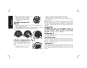
...speed control dial adjusts the rotation speed of the pad. C Assemble Sanding Pad G (Fig. 5) 1. With the other hand, align the holes and place the disc directly on the hook and loop pad. The hooks will perform is controlled in contact with hook and loop. 1. English 4. Ensure dust shroud (C) is ...shroud does not move while tool is released, the sander head revolutions per minute at which FIG. 6 attach to keep it from the hook and loop pad face. 3. Place supplied wrench (I Attaching Abrasive Disc (Fig. 6) Use 5" (127 mm) sanding discs with a 5-hole dust extraction...
...speed control dial adjusts the rotation speed of the pad. C Assemble Sanding Pad G (Fig. 5) 1. With the other hand, align the holes and place the disc directly on the hook and loop pad. The hooks will perform is controlled in contact with hook and loop. 1. English 4. Ensure dust shroud (C) is ...shroud does not move while tool is released, the sander head revolutions per minute at which FIG. 6 attach to keep it from the hook and loop pad face. 3. Place supplied wrench (I Attaching Abrasive Disc (Fig. 6) Use 5" (127 mm) sanding discs with a 5-hole dust extraction...
Instruction Manual
Page 11
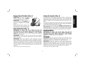
... wear ANSI Z87.1 approved eye protection when performing this tool with perforated paper unless the dust collection system is in the "OFF" position. Periodically clean hook and loop pad. 9 A B Dust Collection (Fig. 1) WARNING: To reduce the risk of injury, turn it from the premises daily. Remove coated dust particles from power source before...
... wear ANSI Z87.1 approved eye protection when performing this tool with perforated paper unless the dust collection system is in the "OFF" position. Periodically clean hook and loop pad. 9 A B Dust Collection (Fig. 1) WARNING: To reduce the risk of injury, turn it from the premises daily. Remove coated dust particles from power source before...


