Hardware Reference
Page 4
...Switch IP address 11 Date and time settings 12 Brocade 5100 Operation In this chapter 17 Powering the Brocade 5100 on and off 17 LED activity interpretation 17 Brocade 5100 LEDs 17 LED locations 18 LED Patterns 19 POST and boot specifications 20 Interpreting POST...5100 Specifications In this appendix 27 Switch components 27 Weight and physical dimensions 28 Facility requirements 28 Power supply specifications 28 Environmental requirements 29 General specifications 29 Data transmission ranges 30 Memory specifications 31 Fibre Channel port specifications 31 Serial port ...
...Switch IP address 11 Date and time settings 12 Brocade 5100 Operation In this chapter 17 Powering the Brocade 5100 on and off 17 LED activity interpretation 17 Brocade 5100 LEDs 17 LED locations 18 LED Patterns 19 POST and boot specifications 20 Interpreting POST...5100 Specifications In this appendix 27 Switch components 27 Weight and physical dimensions 28 Facility requirements 28 Power supply specifications 28 Environmental requirements 29 General specifications 29 Data transmission ranges 30 Memory specifications 31 Fibre Channel port specifications 31 Serial port ...

Hardware Reference
Page 22
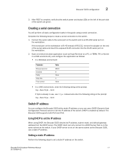
... protect against AC failure. In this installation, the port side of the switch is set . If you do not want to boot and complete POST. Power on separate circuits to slide out the cool-air side of the switch is flush with the edge of the cabinet. • To allow the port side... in a cabinet. Connect the power cords to both power supplies, and then to power sources on the power supplies by flipping both AC switches to the network until POST is time to the Brocade 5100. 1. The power supply LEDs display amber until the IP address is connected and turned on how to...
... protect against AC failure. In this installation, the port side of the switch is set . If you do not want to boot and complete POST. Power on separate circuits to slide out the cool-air side of the switch is flush with the edge of the cabinet. • To allow the port side... in a cabinet. Connect the power cords to both power supplies, and then to power sources on the power supplies by flipping both AC switches to the network until POST is time to the Brocade 5100. 1. The power supply LEDs display amber until the IP address is connected and turned on how to...
Hardware Reference
Page 23
... and status LEDs on the workstation. Connect the serial cable to the serial port on the switch and to set the IP address of the switch are green. After POST is complete, verify that is enabled by default. Setting a static IP address Perform the following steps to create a ...serial connection to set the IP address When using a serial connection. DHCP is on the switch. The Brocade 5100 supports both...
... and status LEDs on the workstation. Connect the serial cable to the serial port on the switch and to set the IP address of the switch are green. After POST is complete, verify that is enabled by default. Setting a static IP address Perform the following steps to create a ...serial connection to set the IP address When using a serial connection. DHCP is on the switch. The Brocade 5100 supports both...

Hardware Reference
Page 29
...LEDs, one or both power supplies by default each Fibre Channel port, located above ) on the left side • One power status LED (below) on the left of the ON/OFF rocker switch on the non-port side of the switch Brocade 5100 Hardware Reference Manual 17 53-1000854-02 This... up to several minutes to boot and complete POST. it can be determined through the activity of the colors during boot, POST, or other diagnostic tests. then, set the AC power switches to "I". Sometimes, the LEDs flash either of the LEDs on the switch. Brocade 5100 Operation Chapter 3 In this chapter...
...LEDs, one or both power supplies by default each Fibre Channel port, located above ) on the left side • One power status LED (below) on the left of the ON/OFF rocker switch on the non-port side of the switch Brocade 5100 Hardware Reference Manual 17 53-1000854-02 This... up to several minutes to boot and complete POST. it can be determined through the activity of the colors during boot, POST, or other diagnostic tests. then, set the AC power switches to "I". Sometimes, the LEDs flash either of the LEDs on the switch. Brocade 5100 Operation Chapter 3 In this chapter...

Hardware Reference
Page 32
...Port is running . Steady green Port is turned on the cause of a loopback cable or incompatible switch connection. at 4 Gbps; POST and boot specifications When the switch is online (connected to external No action required. Initializes the operating system. 3. Contact Technical Support if...log or the command line interface. Steady amber (for details on or rebooted, the switch performs POST. but is receiving light or signal carrier No action required. Conducts preliminary POST diagnostics. 2. Total boot time with random flashes) Port is online and frames are...
...Port is running . Steady green Port is turned on the cause of a loopback cable or incompatible switch connection. at 4 Gbps; POST and boot specifications When the switch is online (connected to external No action required. Initializes the operating system. 3. Contact Technical Support if...log or the command line interface. Steady amber (for details on or rebooted, the switch performs POST. but is receiving light or signal carrier No action required. Conducts preliminary POST diagnostics. 2. Total boot time with random flashes) Port is online and frames are...

Hardware Reference
Page 33
.... If there is powered on accessing the error log, refer to POST, boot includes the following tasks after POST is not successful, the switch did not successfully complete POST. For information about all components are written to the Fabric OS Message...-replaceable units, described in a fabric configuration. 4. Interpreting POST results 3 4. Runs diagnostic tests on the terminal of failure. Complete the following sections. Interpreting POST results POST is a system check that the switch prompt displays on several functions, including circuitry, port functionality,...
.... If there is powered on accessing the error log, refer to POST, boot includes the following tasks after POST is not successful, the switch did not successfully complete POST. For information about all components are written to the Fabric OS Message...-replaceable units, described in a fabric configuration. 4. Interpreting POST results 3 4. Runs diagnostic tests on the terminal of failure. Complete the following sections. Interpreting POST results POST is a system check that the switch prompt displays on several functions, including circuitry, port functionality,...

Hardware Reference
Page 34
...-pad gold-plated PCB-edge connector on the port, as shown in a Mod_Inv state. This includes tests of port slot Diagnostic tests In addition to POST, the Fabric OS includes diagnostic tests to install an SFP. 1. Complete the following steps to help you troubleshoot the hardware and firmware. Fabric OS also...
...-pad gold-plated PCB-edge connector on the port, as shown in a Mod_Inv state. This includes tests of port slot Diagnostic tests In addition to POST, the Fabric OS includes diagnostic tests to install an SFP. 1. Complete the following steps to help you troubleshoot the hardware and firmware. Fabric OS also...

Hardware Reference
Page 36
...POST) each time it is flashing amber and green, it could mean the fan has failed. For more information about upgrading the version of the management options listed in the event of status. • In Advanced Web Tools, check the Fan Status icon background color. Ethernet or serial connection IP over Fibre Channel... the Brocade 5100 to monitor the fabric topology, port status, physical status, and other information to help you analyze switch performance and to the Fabric OS Administrator's Guide and the Fabric OS Command Reference Manual. connection Management Server For information...
...POST) each time it is flashing amber and green, it could mean the fan has failed. For more information about upgrading the version of the management options listed in the event of status. • In Advanced Web Tools, check the Fan Status icon background color. Ethernet or serial connection IP over Fibre Channel... the Brocade 5100 to monitor the fabric topology, port status, physical status, and other information to help you analyze switch performance and to the Fabric OS Administrator's Guide and the Fabric OS Command Reference Manual. connection Management Server For information...

Hardware Reference
Page 51
...Trunking, 4, 5 BSMI statement (Chinese), 34 C Canadian requirements, 34 CE statement, 34 China RoHS, 36 class Fibre Channel classes supported, 29 Command line interface (CLI), 24 components, switch, 27 configuring date and time, 12 NTP, 14 configuring the Brocade 5100, 10 D date, 13 date and ...LEDs, 17 I installing a Brocade 5100 into an EIA cabinet, 10 installing a stand-alone Brocade 5100, 9 installing an SFP, 22 interpreting POST results, 21 IP over Fibre Channel (FC-IP), 29 ISL trunking groups, 5 items required for installation, 9 L laser compliance, 35 latency, 30 LEDs interpreting, 17 on...
...Trunking, 4, 5 BSMI statement (Chinese), 34 C Canadian requirements, 34 CE statement, 34 China RoHS, 36 class Fibre Channel classes supported, 29 Command line interface (CLI), 24 components, switch, 27 configuring date and time, 12 NTP, 14 configuring the Brocade 5100, 10 D date, 13 date and ...LEDs, 17 I installing a Brocade 5100 into an EIA cabinet, 10 installing a stand-alone Brocade 5100, 9 installing an SFP, 22 interpreting POST results, 21 IP over Fibre Channel (FC-IP), 29 ISL trunking groups, 5 items required for installation, 9 L laser compliance, 35 latency, 30 LEDs interpreting, 17 on...
Hardware Reference
Page 52
... 14 P physical dimensions of switch, 28 port configurable types, 29 Ethernet port, 27 Fibre Channel port, 31 serial port, 27, 32 trunking, 4, 5 port numbering, 3 port status LEDs, 17 Ports On Demand, 5 ports, enabling, 5 ports, numbering, 3 POST error messages, 21 interpreting, 21 POST and boot specifications, 20 power... and time, 12 Setting time zones, 14 settings date and time, 12 SNMP, 24 specifications Fibre Channel ports, 31 general, 29 power supply, 28 serial port, 32 switch components, 27 physical dimensions, 28 weight, 28 system status LED, 17 T temperature requirements, 29 tests, ...
... 14 P physical dimensions of switch, 28 port configurable types, 29 Ethernet port, 27 Fibre Channel port, 31 serial port, 27, 32 trunking, 4, 5 port numbering, 3 port status LEDs, 17 Ports On Demand, 5 ports, enabling, 5 ports, numbering, 3 POST error messages, 21 interpreting, 21 POST and boot specifications, 20 power... and time, 12 Setting time zones, 14 settings date and time, 12 SNMP, 24 specifications Fibre Channel ports, 31 general, 29 power supply, 28 serial port, 32 switch components, 27 physical dimensions, 28 weight, 28 system status LED, 17 T temperature requirements, 29 tests, ...