
Hardware Reference
Page 2
... trademarks or service marks of, and are trademarks of the programming source code, please visit http://www.brocade.com/support/oscd. The product described by this document may contain "open source software, and obtain a copy of Brocade Communications Systems, Inc., in the United States and/or in Brocade products, view the licensing terms applicable to any time, without...
... trademarks or service marks of, and are trademarks of the programming source code, please visit http://www.brocade.com/support/oscd. The product described by this document may contain "open source software, and obtain a copy of Brocade Communications Systems, Inc., in the United States and/or in Brocade products, view the licensing terms applicable to any time, without...
Hardware Reference
Page 3
... Brocade 5100 4 Field replaceable units (FRUs 4 Ports on Demand license 5 ISL trunking groups 5 Chapter 2 Brocade 5100 Installation and Configuration In this chapter 7 Items included with the Brocade 5100 7 Installation and safety considerations 7 Electrical considerations 8 Environmental considerations 8 Cabinet considerations 8 Recommendations for cable management 8 Items required for installation 9 Installing a standalone Brocade 5100 9 Cabinet installation for a Brocade 5100 10 Brocade 5100 Hardware Reference Manual iii 53-1000854...
... Brocade 5100 4 Field replaceable units (FRUs 4 Ports on Demand license 5 ISL trunking groups 5 Chapter 2 Brocade 5100 Installation and Configuration In this chapter 7 Items included with the Brocade 5100 7 Installation and safety considerations 7 Electrical considerations 8 Environmental considerations 8 Cabinet considerations 8 Recommendations for cable management 8 Items required for installation 9 Installing a standalone Brocade 5100 9 Cabinet installation for a Brocade 5100 10 Brocade 5100 Hardware Reference Manual iii 53-1000854...
Hardware Reference
Page 4
... 21 Installing an SFP 22 Diagnostic tests 22 Field Replaceable Units (FRUs 23 Power supply/fan assembly FRU replacement 23 Managing the Brocade 5100 24 Brocade 5100 Specifications In this appendix 27 Switch components 27 Weight and physical dimensions 28 Facility requirements 28 Power supply specifications 28 Environmental requirements 29 General specifications 29 Data transmission ranges 30 Memory specifications 31 Fibre Channel port specifications 31 Serial port specifications 32 iv Brocade 5100 Hardware Reference Manual 53...
... 21 Installing an SFP 22 Diagnostic tests 22 Field Replaceable Units (FRUs 23 Power supply/fan assembly FRU replacement 23 Managing the Brocade 5100 24 Brocade 5100 Specifications In this appendix 27 Switch components 27 Weight and physical dimensions 28 Facility requirements 28 Power supply specifications 28 Environmental requirements 29 General specifications 29 Data transmission ranges 30 Memory specifications 31 Fibre Channel port specifications 31 Serial port specifications 32 iv Brocade 5100 Hardware Reference Manual 53...

Hardware Reference
Page 10
... cost for hardware, firmware, and software support, including product repairs and part ordering. For additional resource information, visit the Technical Committee T11 Web site. General Information • Switch model • Switch operating system version • Error numbers and messages received • supportSave command output • Detailed description of any troubleshooting steps already performed and the results • Serial console and Telnet session logs • syslog message logs x Brocade 5100 Hardware Reference Manual 53...
... cost for hardware, firmware, and software support, including product repairs and part ordering. For additional resource information, visit the Technical Committee T11 Web site. General Information • Switch model • Switch operating system version • Error numbers and messages received • supportSave command output • Detailed description of any troubleshooting steps already performed and the results • Serial console and Telnet session logs • syslog message logs x Brocade 5100 Hardware Reference Manual 53...

Hardware Reference
Page 13
... Ethernet management port, that in conjunction with EZSwitchSetup, supports switch IP address discovery and configuration, eliminating the need to attach a serial cable to configure the switch IP address and greatly increasing the ease of use the Brocade 5100 to create very dense fabrics in large-scale enterprise SANs and can use . • USB port that provides storage for firmware updates, output of the supportSave command and storage for configuration uploads and downloads...
... Ethernet management port, that in conjunction with EZSwitchSetup, supports switch IP address discovery and configuration, eliminating the need to attach a serial cable to configure the switch IP address and greatly increasing the ease of use the Brocade 5100 to create very dense fabrics in large-scale enterprise SANs and can use . • USB port that provides storage for firmware updates, output of the supportSave command and storage for configuration uploads and downloads...

Hardware Reference
Page 14
... (Fabric OS), which delivers distributed intelligence throughout the network and enables a wide range of the Brocade 5100 includes the system status LED, console port, Ethernet port and LEDs, USB port, and Fibre Channel ports and the corresponding port status LEDs. 1 Port side of the Brocade 5100 • Inter-Switch Link (ISL) Trunking (licensable), which allows up to eight ports (at 1, 2, 4, or 8 Gbps speeds) between a pair of switches combined to form a single, logical ISL with...
... (Fabric OS), which delivers distributed intelligence throughout the network and enables a wide range of the Brocade 5100 includes the system status LED, console port, Ethernet port and LEDs, USB port, and Fibre Channel ports and the corresponding port status LEDs. 1 Port side of the Brocade 5100 • Inter-Switch Link (ISL) Trunking (licensable), which allows up to eight ports (at 1, 2, 4, or 8 Gbps speeds) between a pair of switches combined to form a single, logical ISL with...
Hardware Reference
Page 20
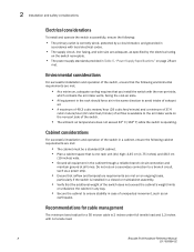
... breaker, and grounded in accordance with local electrical codes. • The supply circuit, line fusing, and wire size are adequate, as specified by the electrical rating on the switch nameplate. • The power supply standards provided in Table 5, "Power Supply Specifications" on page 28 are met on an ongoing basis, particularly if the switch is installed in a closed or multicabinet assembly. • Verify that...
... breaker, and grounded in accordance with local electrical codes. • The supply circuit, line fusing, and wire size are adequate, as specified by the electrical rating on the switch nameplate. • The power supply standards provided in Table 5, "Power Supply Specifications" on page 28 are met on an ongoing basis, particularly if the switch is installed in a closed or multicabinet assembly. • Verify that...
Hardware Reference
Page 21
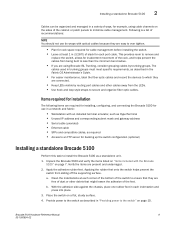
...; Unused IP address and corresponding subnet mask and gateway address • Serial cable (provided) • Ethernet cable • SFPs and compatible cables, as required • Access to an FTP server for backing up the switch configuration (optional) Installing a standalone Brocade 5100 Perform this task to secure and organize fiber optic cables. Place the switch on page 7. Following is a list of recommendations: NOTE You should not use in a network and fabric...
...; Unused IP address and corresponding subnet mask and gateway address • Serial cable (provided) • Ethernet cable • SFPs and compatible cables, as required • Access to an FTP server for backing up the switch configuration (optional) Installing a standalone Brocade 5100 Perform this task to secure and organize fiber optic cables. Place the switch on page 7. Following is a list of recommendations: NOTE You should not use in a network and fabric...

Hardware Reference
Page 22
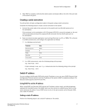
.... A rack mount kit can also use one of three rack mount kits to the switch as soon as a standalone switch, it power and a basic configuration. Power on the power supplies by flipping both power supplies, and then to power sources on separate circuits to protect against AC failure. You can be installed in the fiber optic cables. The power supply LEDs display amber until the IP address is complete, and then change to green. Providing power...
.... A rack mount kit can also use one of three rack mount kits to the switch as soon as a standalone switch, it power and a basic configuration. Power on the power supplies by flipping both power supplies, and then to power sources on separate circuits to protect against AC failure. You can be installed in the fiber optic cables. The power supply LEDs display amber until the IP address is complete, and then change to green. Providing power...
Hardware Reference
Page 23
... application as the Brocade 5100, use a DHCP (Dynamic Host Configuration Protocol) server to a DHCP server that the switch power and status LEDs on the workstation. If your DHCP server is enabled by default. Brocade 5100 configuration 2 3. The Brocade 5100 supports both IPv4 and IPv6. Complete the following steps to the switch. 1. Setting a static IP address Perform the following steps to create a serial connection to set the IP address of the serial cable and insert the exposed RJ...
... application as the Brocade 5100, use a DHCP (Dynamic Host Configuration Protocol) server to a DHCP server that the switch power and status LEDs on the workstation. If your DHCP server is enabled by default. Brocade 5100 configuration 2 3. The Brocade 5100 supports both IPv4 and IPv6. Complete the following steps to the switch. 1. Setting a static IP address Perform the following steps to create a serial connection to set the IP address of the serial cable and insert the exposed RJ...

Hardware Reference
Page 24
... can view the time zone settings. You can set the time zone for a switch using the default password, which is not set the time zones. • The tsTimeZone setting automatically adjusts for Daylight Savings Time. • Changing the time zone on a switch updates the local time zone setup and is being changed...Done. 3. The tsTimeZone command allows you are in the GMT time zone (0,0). Time zones You can set the Ethernet IP address. The tsTimeZone command includes an...
... can view the time zone settings. You can set the time zone for a switch using the default password, which is not set the time zones. • The tsTimeZone setting automatically adjusts for Daylight Savings Time. • Changing the time zone on a switch updates the local time zone setup and is being changed...Done. 3. The tsTimeZone command allows you are in the GMT time zone (0,0). Time zones You can set the Ethernet IP address. The tsTimeZone command includes an...

Hardware Reference
Page 25
... is the date; Enter the date command, using the default password, which is supported for high availability. switch:admin> date Fri Sep 29 17:01:48 UTC 2007 switch:admin> date "0927123007" Brocade 5100 Hardware Reference Manual 13 53-1000854-02 The principal or primary FCS switch synchronizes its time synchronized with at least one external NTP server. If the active NTP server configured is IPv6, then distributing the...
... is the date; Enter the date command, using the default password, which is supported for high availability. switch:admin> date Fri Sep 29 17:01:48 UTC 2007 switch:admin> date "0927123007" Brocade 5100 Hardware Reference Manual 13 53-1000854-02 The principal or primary FCS switch synchronizes its time synchronized with at least one external NTP server. If the active NTP server configured is IPv6, then distributing the...

Hardware Reference
Page 29
... setting each time it is normal; The lights are three possible LED states: no light, a steady light, and a flashing light. Sometimes, the LEDs flash either of the ON/OFF rocker switch on . it can be determined through the activity of the switch Brocade 5100 Hardware Reference Manual 17 53-1000854-02 To power the Brocade 5100 off, power off To power the Brocade 5100 on, connect one for each Fibre Channel port...
... setting each time it is normal; The lights are three possible LED states: no light, a steady light, and a flashing light. Sometimes, the LEDs flash either of the ON/OFF rocker switch on . it can be determined through the activity of the switch Brocade 5100 Hardware Reference Manual 17 53-1000854-02 To power the Brocade 5100 off, power off To power the Brocade 5100 on, connect one for each Fibre Channel port...
Hardware Reference
Page 31
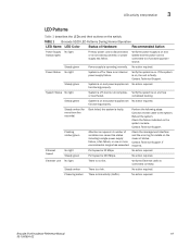
... required. Check the management interface and the error log for more environmental ranges has exceeded. Verify the power supply is on the switch. System Status No light System is off or there is an internal power supply failure. functioning properly. No action required. A number of Hardware Recommended Action Power Supply No light Status (right) Primary power cord is disconnected or is link activity (traffic). Ethernet Speed No light Steady green Port speed is operating normally. Port speed is connected correctly...
... required. Check the management interface and the error log for more environmental ranges has exceeded. Verify the power supply is on the switch. System Status No light System is off or there is an internal power supply failure. functioning properly. No action required. A number of Hardware Recommended Action Power Supply No light Status (right) Primary power cord is disconnected or is link activity (traffic). Ethernet Speed No light Steady green Port speed is operating normally. Port speed is connected correctly...

Hardware Reference
Page 33
... errShow command. Review the switch system log for repair. 3. Performs universal port configuration. 2. Contact your switch supplier for errors. Maintaining the Brocade 5100 The Brocade 5100 does not require any errors were detected: 1. Interpreting POST results POST is a system check that the LEDs on the switch are healthy. Verify that all referenced commands, and on , rebooted, or reset. Initializes links. 3. Enables normal port operation. If there is powered on accessing the error log, refer...
... errShow command. Review the switch system log for repair. 3. Performs universal port configuration. 2. Contact your switch supplier for errors. Maintaining the Brocade 5100 The Brocade 5100 does not require any errors were detected: 1. Interpreting POST results POST is a system check that the LEDs on the switch are healthy. Verify that all referenced commands, and on , rebooted, or reset. Initializes links. 3. Enables normal port operation. If there is powered on accessing the error log, refer...
Hardware Reference
Page 35
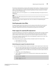
... speed of each FRU. Power supply/fan assembly FRU replacement The Brocade 5100 fans are keyed to the I/O switch. If the light does not turn green, the power supply needs to be replaced onsite without the use of 1, 2, 4, and 8 Gbps depending on the left • Power supply #2 is connected to verify the serializer/deserializer interface, transceiver, and cable. Diagnostic tests are provided with all replacement units ordered. There is OK Brocade 5100 Hardware Reference Manual...
... speed of each FRU. Power supply/fan assembly FRU replacement The Brocade 5100 fans are keyed to the I/O switch. If the light does not turn green, the power supply needs to be replaced onsite without the use of 1, 2, 4, and 8 Gbps depending on the left • Power supply #2 is connected to verify the serializer/deserializer interface, transceiver, and cable. Diagnostic tests are provided with all replacement units ordered. There is OK Brocade 5100 Hardware Reference Manual...

Hardware Reference
Page 36
..., refer to the MIB Reference Manual. Ethernet or serial connection Standard SNMP applications For information, refer to the Web Tools Administrator's Guide. Ethernet or serial connection IP over Fibre Channel IP over Fibre Channel IP over Fibre Channel IP over Fibre Channel Native in the error log. TABLE 2 Management Options for details on replacing the power/fan units, see the Brocade 5100 Power Supply and Fan Assembly Replacement Procedure. The green power supply/fan LED will be either yellow or red if the fan has failed. It will also flash...
..., refer to the MIB Reference Manual. Ethernet or serial connection Standard SNMP applications For information, refer to the Web Tools Administrator's Guide. Ethernet or serial connection IP over Fibre Channel IP over Fibre Channel IP over Fibre Channel IP over Fibre Channel Native in the error log. TABLE 2 Management Options for details on replacing the power/fan units, see the Brocade 5100 Power Supply and Fan Assembly Replacement Procedure. The green power supply/fan LED will be either yellow or red if the fan has failed. It will also flash...
Hardware Reference
Page 44
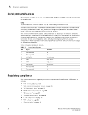
..." on the port when not in use this port to connect a terminal to the port to re-initialize the switch defaults, restoring the switch to its factory default settings if Flash memory contents are fixed at 9600 baud, 8 data bits, and no parity, with flow control set to the switch. This is for initial IP address configuration and for performance of the switch. The serial port's parameters are lost. NOTE To protect the serial port from damage...
..." on the port when not in use this port to connect a terminal to the port to re-initialize the switch defaults, restoring the switch to its factory default settings if Flash memory contents are fixed at 9600 baud, 8 data bits, and no parity, with flow control set to the switch. This is for initial IP address configuration and for performance of the switch. The serial port's parameters are lost. NOTE To protect the serial port from damage...

Hardware Reference
Page 51
..., aggregate, 30 Brocade Advanced Web Tools, 24 Brocade Fabric Manager, 24 Brocade ISL Trunking, 4, 5 BSMI statement (Chinese), 34 C Canadian requirements, 34 CE statement, 34 China RoHS, 36 class Fibre Channel classes supported, 29 Command line interface (CLI), 24 components, switch, 27 configuring date and time, 12 NTP, 14 configuring the Brocade 5100, 10 D date, 13 date and time, 12 diagnostic tests about, 22 E EFCM, 24 Brocade 5100 Hardware Reference Manual...
..., aggregate, 30 Brocade Advanced Web Tools, 24 Brocade Fabric Manager, 24 Brocade ISL Trunking, 4, 5 BSMI statement (Chinese), 34 C Canadian requirements, 34 CE statement, 34 China RoHS, 36 class Fibre Channel classes supported, 29 Command line interface (CLI), 24 components, switch, 27 configuring date and time, 12 NTP, 14 configuring the Brocade 5100, 10 D date, 13 date and time, 12 diagnostic tests about, 22 E EFCM, 24 Brocade 5100 Hardware Reference Manual...

Hardware Reference
Page 52
...), 33 monitoring through LED activity, 17 N NTP access, 14 P physical dimensions of switch, 28 port configurable types, 29 Ethernet port, 27 Fibre Channel port, 31 serial port, 27, 32 trunking, 4, 5 port numbering, 3 port status LEDs, 17 Ports On Demand, 5 ports, enabling, 5 ports, numbering, 3 POST error messages, 21 interpreting, 21 POST and boot specifications, 20 power status LED, 17 power supply general information, 27 specifications, 28 power supply status LED, 17 protocol, ANSI, 29 provide power to the switch, 10 R rack requirements, 28 recommendations for cable management, 8 regulatory...
...), 33 monitoring through LED activity, 17 N NTP access, 14 P physical dimensions of switch, 28 port configurable types, 29 Ethernet port, 27 Fibre Channel port, 31 serial port, 27, 32 trunking, 4, 5 port numbering, 3 port status LEDs, 17 Ports On Demand, 5 ports, enabling, 5 ports, numbering, 3 POST error messages, 21 interpreting, 21 POST and boot specifications, 20 power status LED, 17 power supply general information, 27 specifications, 28 power supply status LED, 17 protocol, ANSI, 29 provide power to the switch, 10 R rack requirements, 28 recommendations for cable management, 8 regulatory...

