User Guide
Page 5
EVGA X58 SLI Motherboard Hard Disk Boot Priority 44 CD-ROM Device Priority 44 First/Second/Third Boot Device 44 Boot Other Device 45 Boot Up NumLock Status 45 Security Option 45 Integrated Peripherals Menu 46 Legacy Devices 46 OnChip PATA/SATA Device 47 Onboard Device 48 USB Device Settings 49 Power Management Setup Menu 50 ACPI Function ...50 ACPI Suspend Type 51 Run VGABIOS if S3 Resume 51 Soft-Off by PWR-BTTN 51 Wake-Up by PCI Card 51 USB KB Wake-Up From S3...
EVGA X58 SLI Motherboard Hard Disk Boot Priority 44 CD-ROM Device Priority 44 First/Second/Third Boot Device 44 Boot Other Device 45 Boot Up NumLock Status 45 Security Option 45 Integrated Peripherals Menu 46 Legacy Devices 46 OnChip PATA/SATA Device 47 Onboard Device 48 USB Device Settings 49 Power Management Setup Menu 50 ACPI Function ...50 ACPI Suspend Type 51 Run VGABIOS if S3 Resume 51 Soft-Off by PWR-BTTN 51 Wake-Up by PCI Card 51 USB KB Wake-Up From S3...

User Guide
Page 11
... ) Onboard LAN Integrated Dual LAN ports Supports 10/100/1000 Mbit/sec Ethernet Onboard IEEE1394a (Firewire) Support hot plug Two IEEE1394a ports (one rear panel port, one onboard header) with a rate transmission of 400 Mbps Onboard Audio Realtek High-Definition audio Supports 8-channel audio Supports S/PDIF output (Optical and COAX) Supports Jack-Sensing function Triple PCI Express Support Three (3) PCI-E 2.0 Slots Supports 4 GB/sec (8 GB/sec concurrent) bandwidth Low power consumption and power management features Green Function Supports ACPI (Advanced Configuration and Power Interface...
... ) Onboard LAN Integrated Dual LAN ports Supports 10/100/1000 Mbit/sec Ethernet Onboard IEEE1394a (Firewire) Support hot plug Two IEEE1394a ports (one rear panel port, one onboard header) with a rate transmission of 400 Mbps Onboard Audio Realtek High-Definition audio Supports 8-channel audio Supports S/PDIF output (Optical and COAX) Supports Jack-Sensing function Triple PCI Express Support Three (3) PCI-E 2.0 Slots Supports 4 GB/sec (8 GB/sec concurrent) bandwidth Low power consumption and power management features Green Function Supports ACPI (Advanced Configuration and Power Interface...

User Guide
Page 13
... drivers and software needed to a SATA power connector. 1 - SATA Data Cables Used to support the Serial ATA protocol and each one (1) additional IEEE1394a port to the back panel of the chassis. 6 - IEEE1394a (Firewire) Bracket Provides one connects a single drive to either the front or back panels of the chassis. 1 - 4-Port USB 2.0 Bracket Provides four additional USB ports to the motherboard. 1 - IDE Data Cable Passes data between the IDE connection on the motherboard and IDE device. 1 - 2-Way SLI Bridge Bridges two (2) graphic cards...
... drivers and software needed to a SATA power connector. 1 - SATA Data Cables Used to support the Serial ATA protocol and each one (1) additional IEEE1394a port to the back panel of the chassis. 6 - IEEE1394a (Firewire) Bracket Provides one connects a single drive to either the front or back panels of the chassis. 1 - 4-Port USB 2.0 Bracket Provides four additional USB ports to the motherboard. 1 - IDE Data Cable Passes data between the IDE connection on the motherboard and IDE device. 1 - 2-Way SLI Bridge Bridges two (2) graphic cards...

User Guide
Page 14
Figure 1 shows the motherboard and Figures 2 shows the back panel connectors. EVGA X58 SLI Motherboard The EVGA X58 SLI Motherboard with the Intel X58 and ICH10R chipset is a PCI Express, SLI-ready motherboard.
Figure 1 shows the motherboard and Figures 2 shows the back panel connectors. EVGA X58 SLI Motherboard The EVGA X58 SLI Motherboard with the Intel X58 and ICH10R chipset is a PCI Express, SLI-ready motherboard.
User Guide
Page 22
...) 8-pin ATX 12V power (PW12) Internal Headers Front panel IEEE 1394a USB Headers Audio COM IDE Serial ATA II Chassis Fans Carefully place the motherboard onto the stand off /spacers located inside the chassis. Ensure that you through all the necessary connections on the motherboard, it is aligned with a recommended minimum of nine (9) screws. If there are studs that stud to prevent short circuits. Align the connectors to the fan assembly instruction. Connecting Cables...
...) 8-pin ATX 12V power (PW12) Internal Headers Front panel IEEE 1394a USB Headers Audio COM IDE Serial ATA II Chassis Fans Carefully place the motherboard onto the stand off /spacers located inside the chassis. Ensure that you through all the necessary connections on the motherboard, it is aligned with a recommended minimum of nine (9) screws. If there are studs that stud to prevent short circuits. Align the connectors to the fan assembly instruction. Connecting Cables...

User Guide
Page 32
... bracket to the chassis back panel with the screw used to accommodate less bandwidth-intensive cards, such as a LAN card, USB card, SCSI card and other cards that comply with PCI specifications. Secure the card's metal bracket to the chassis back panel with the screw used to hold the blank cover. PCI Express x1 Slots There is one PCI Express x1 slot that it could cause a short across the pins. When installing a PCI Express Graphic Card, be sure the...
... bracket to the chassis back panel with the screw used to accommodate less bandwidth-intensive cards, such as a LAN card, USB card, SCSI card and other cards that comply with PCI specifications. Secure the card's metal bracket to the chassis back panel with the screw used to hold the blank cover. PCI Express x1 Slots There is one PCI Express x1 slot that it could cause a short across the pins. When installing a PCI Express Graphic Card, be sure the...

User Guide
Page 41
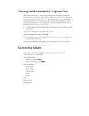
.... Auto Recommended mode. Configuring the BIOS Press Enter to auto-detect IDE and SATA channels in a DEC number : For HDD less than 528 MB but not supporting LBA. ESC:Abort Once the channel is no HDD installed or set the channel to [Manual] and change Access Mode to display a window that tells you can auto-detect the hard disk when booting up. You can manually enter the values or you can press Enter to [CHS], you the min and max...
.... Auto Recommended mode. Configuring the BIOS Press Enter to auto-detect IDE and SATA channels in a DEC number : For HDD less than 528 MB but not supporting LBA. ESC:Abort Once the channel is no HDD installed or set the channel to [Manual] and change Access Mode to display a window that tells you can auto-detect the hard disk when booting up. You can manually enter the values or you can press Enter to [CHS], you the min and max...
User Guide
Page 47
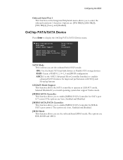
... you set the onboard Serial JM363 mode. AHCI Configurations SATA Mode LEGACY Mode Support [Press Enter] [IDE] [Disabled] JMB362 SATA Controller [Auto] JMB363 SATA/PATA Controller [Auto] JMB363 Mode [IDE] SATA Mode This is allows you set the onboard Serial SATA mode. Selected Disabled if you to enable JMB363 SATA Controller for improved performance with NCQ and Hot-plug features LEGACY Mode Support This function allows the SATA controller to display the OnChip PATA/SATA Device menu. The options are Auto, Enabled and Disabled. IDE: Use the Serial ATA hard disk drivers as...
... you set the onboard Serial JM363 mode. AHCI Configurations SATA Mode LEGACY Mode Support [Press Enter] [IDE] [Disabled] JMB362 SATA Controller [Auto] JMB363 SATA/PATA Controller [Auto] JMB363 Mode [IDE] SATA Mode This is allows you set the onboard Serial SATA mode. Selected Disabled if you to enable JMB363 SATA Controller for improved performance with NCQ and Hot-plug features LEGACY Mode Support This function allows the SATA controller to display the OnChip PATA/SATA Device menu. The options are Auto, Enabled and Disabled. IDE: Use the Serial ATA hard disk drivers as...
User Guide
Page 48
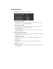
... to set the onboard Realtek GigaLan function for LAN2. High Definition Audio This function allows you to display the Onboard Device menu. The options are Auto, Enabled and Disabled. Onboard Device Press Enter to enable or disable the IEEE1394 (Firewire) interface. Realtek GigaLan (LAN1) Realtek GigaLan (LAN2) [Auto] [Auto] PE4 Slot (PCIE x1) Realtek Lan PXE Boot ROM TI 1394 Setting High Definition Audio P80 Show CPU Temp. [Auto] [Disabled] [Enabled] [Enabled] [Enabled] Realtek GigaLan (LAN1) Use this function is enabled the onboard Post Port LED will display the CPU temperature...
... to set the onboard Realtek GigaLan function for LAN2. High Definition Audio This function allows you to display the Onboard Device menu. The options are Auto, Enabled and Disabled. Onboard Device Press Enter to enable or disable the IEEE1394 (Firewire) interface. Realtek GigaLan (LAN1) Realtek GigaLan (LAN2) [Auto] [Auto] PE4 Slot (PCIE x1) Realtek Lan PXE Boot ROM TI 1394 Setting High Definition Audio P80 Show CPU Temp. [Auto] [Disabled] [Enabled] [Enabled] [Enabled] Realtek GigaLan (LAN1) Use this function is enabled the onboard Post Port LED will display the CPU temperature...
User Guide
Page 49
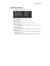
... enable or disable support for USB mouse under DOS. USB 2.0 Controller Use this function to enable the USB 1.0 controller. USB Keyboard Function Use this function to enable or disable legacy support of USB Mass Storage USB 1.0 Controller USB 2.0 Controller USB Operation Mode USB Keyboard Function USB Mouse Function USB Storage Function [Enabled] [Enabled] [High Speed] [Enabled] [Enabled] [Enabled] *** USB Mass Storage Device Boot Setting *** USB 1.0 Controller Use this function to display the USB Device Settings menu. Configuring the BIOS USB Device Settings Press Enter to enable...
... enable or disable support for USB mouse under DOS. USB 2.0 Controller Use this function to enable the USB 1.0 controller. USB Keyboard Function Use this function to enable or disable legacy support of USB Mass Storage USB 1.0 Controller USB 2.0 Controller USB Operation Mode USB Keyboard Function USB Mouse Function USB Storage Function [Enabled] [Enabled] [High Speed] [Enabled] [Enabled] [Enabled] *** USB Mass Storage Device Boot Setting *** USB 1.0 Controller Use this function to display the USB Device Settings menu. Configuring the BIOS USB Device Settings Press Enter to enable...
User Guide
Page 50
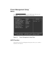
...)] [Auto] [Instant-Off] [Enabled] [Disabled] [Disabled] 0 0 : 0 : 0 [Disabled] Ctrl-F1 [Off] Item Help Main Level :Move Enter:Select +/-/PU/PD:Value F10:Save ESC:Exit F1:General Help F5:Previous Values F6:Fail-Safe Defaults F7:Optimized Defaults Figure 8. Power Management Setup Menu ACPI Function This function on the Power Management Setup menu allows you to display the Power Management Setup menu. Power Management Setup Menu Select Power Management Setup from the CMOS Setup Utility menu and press Enter to enable or disable...
...)] [Auto] [Instant-Off] [Enabled] [Disabled] [Disabled] 0 0 : 0 : 0 [Disabled] Ctrl-F1 [Off] Item Help Main Level :Move Enter:Select +/-/PU/PD:Value F10:Save ESC:Exit F1:General Help F5:Previous Values F6:Fail-Safe Defaults F7:Optimized Defaults Figure 8. Power Management Setup Menu ACPI Function This function on the Power Management Setup menu allows you to display the Power Management Setup menu. Power Management Setup Menu Select Power Management Setup from the CMOS Setup Utility menu and press Enter to enable or disable...

User Guide
Page 51
... Setup menu allows a USB keyboard device to prevent poweron by PCI Card This function on the Power Management Setup menu allows PCI Card to select from are Auto, Yes and No. Set to [Disable] to wake-up the system from S3 state. Run VGABIOS if S3 Resume This function on the Power Management Setup menu allows you determines whether or not to enable the system to select an ACPI Suspend Type. Configuring the BIOS ACPI...
... Setup menu allows a USB keyboard device to prevent poweron by PCI Card This function on the Power Management Setup menu allows PCI Card to select from are Auto, Yes and No. Set to [Disable] to wake-up the system from S3 state. Run VGABIOS if S3 Resume This function on the Power Management Setup menu allows you determines whether or not to enable the system to select an ACPI Suspend Type. Configuring the BIOS ACPI...
User Guide
Page 53
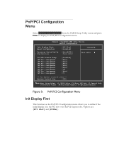
...Options are [PCI Slot] and [PCIEx]. PnP/PCI Configuration Menu Select PnP/PCI Configuration from the CMOS Setup Utility menu and press Enter to define if the initial display is in the PCI slot or in the PCI Express slot. Phoenix - PnP/PCI Configuration Menu Init Display First This function on the PnP/PCI Configuration menu allows you to display the PnP/PCI Configuration menu. AwardBIOS CMOS Setup Utility PnP/PCI Configuration Init Display First Reset Configuration Resources Controlled By x IRQ Resources [PCI Slot] [Disabled] [Auto(ESCD)] Press Enter Item Help Main Level PCI/VGA...
...Options are [PCI Slot] and [PCIEx]. PnP/PCI Configuration Menu Select PnP/PCI Configuration from the CMOS Setup Utility menu and press Enter to define if the initial display is in the PCI slot or in the PCI Express slot. Phoenix - PnP/PCI Configuration Menu Init Display First This function on the PnP/PCI Configuration menu allows you to display the PnP/PCI Configuration menu. AwardBIOS CMOS Setup Utility PnP/PCI Configuration Init Display First Reset Configuration Resources Controlled By x IRQ Resources [PCI Slot] [Disabled] [Auto(ESCD)] Press Enter Item Help Main Level PCI/VGA...
User Guide
Page 56
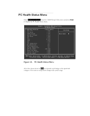
... press Enter to display the PC Health Status menu. Phoenix - AwardBIOS CMOS Setup Utility PC Health Status SmartFan Function VCC 3.3V CPU Vcore DIMM Voltage CPU VTT Voltage IOH Vcore VCC +12V 3VSB VBT CPU temperature NB temperature VREG temperature System temperature CPU Fan Speed Power Fan Speed Chassis Fan Speed AUX Fan Speed [Press Enter] 3.28V 1.19V 1.48V 1.23V 1.08V 4.96V 12.10V 3.23V 3.15V 31oC 55oC 50oC 33oC 3054 RPM 0 RPM 0 RPM 0 RPM Item Help Main...
... press Enter to display the PC Health Status menu. Phoenix - AwardBIOS CMOS Setup Utility PC Health Status SmartFan Function VCC 3.3V CPU Vcore DIMM Voltage CPU VTT Voltage IOH Vcore VCC +12V 3VSB VBT CPU temperature NB temperature VREG temperature System temperature CPU Fan Speed Power Fan Speed Chassis Fan Speed AUX Fan Speed [Press Enter] 3.28V 1.19V 1.48V 1.23V 1.08V 4.96V 12.10V 3.23V 3.15V 31oC 55oC 50oC 33oC 3054 RPM 0 RPM 0 RPM 0 RPM Item Help Main...
User Guide
Page 58
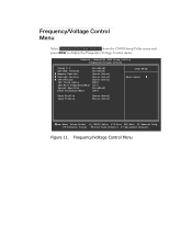
... display the Frequency/Voltage Control menu. Phoenix - Frequency/Voltage Control Menu AwardBIOS CMOS Setup Utility Frequency/Voltage Control Dummy O.C. [Disabled] Extreme Cooling [Disabled] Memory Feature [Press Enter] Voltage Control [Press Enter] CPU Feature [Press Enter] CPU Clock Ratio [22X] CPU Host Frequency(Mhz) [133] Spread Spectrum [Disabled] PCIE Frequency(Mhz) [100] Save Profile Load Profile [Press Enter] [Press Enter] Item Help Main Level :Move Enter:Select +/-/PU/PD:Value F10:Save ESC:Exit F1:General Help F5:Previous Values F6:Fail-Safe Defaults...
... display the Frequency/Voltage Control menu. Phoenix - Frequency/Voltage Control Menu AwardBIOS CMOS Setup Utility Frequency/Voltage Control Dummy O.C. [Disabled] Extreme Cooling [Disabled] Memory Feature [Press Enter] Voltage Control [Press Enter] CPU Feature [Press Enter] CPU Clock Ratio [22X] CPU Host Frequency(Mhz) [133] Spread Spectrum [Disabled] PCIE Frequency(Mhz) [100] Save Profile Load Profile [Press Enter] [Press Enter] Item Help Main Level :Move Enter:Select +/-/PU/PD:Value F10:Save ESC:Exit F1:General Help F5:Previous Values F6:Fail-Safe Defaults...
User Guide
Page 59
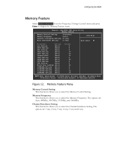
...Memory Control Setting. Memory Frequency This function is allows you to display the Memory Feature menu. The options are 1 way, 2 way, 3 way, 4 way, 5 way and 6 way. AwardBIOS CMOS Setup Utility Memory Feature Memory Control Setting Memory Frequency Channel Interleave Setting Rank Interleave Setting [Disabled] [Auto] [6 way] [4 way] Item Help Main Level Parameters Setting tCL Setting [Auto] tRCD Setting [Auto] tRP Setting [Auto] tRAS Setting [Auto] tRFC Setting [Auto] Command Rate [Auto] tRRD Setting [Auto] tFAW Setting [Auto] tRTP Setting [Auto] tWR Setting [Auto...
...Memory Control Setting. Memory Frequency This function is allows you to display the Memory Feature menu. The options are 1 way, 2 way, 3 way, 4 way, 5 way and 6 way. AwardBIOS CMOS Setup Utility Memory Feature Memory Control Setting Memory Frequency Channel Interleave Setting Rank Interleave Setting [Disabled] [Auto] [6 way] [4 way] Item Help Main Level Parameters Setting tCL Setting [Auto] tRCD Setting [Auto] tRP Setting [Auto] tRAS Setting [Auto] tRFC Setting [Auto] Command Rate [Auto] tRRD Setting [Auto] tFAW Setting [Auto] tRTP Setting [Auto] tWR Setting [Auto...
User Guide
Page 61
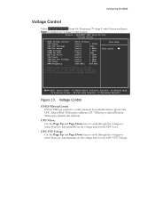
... F5:Previous Values F6:Fail-Safe Defaults F7:Optimized Defaults Figure 13. Voltage Control EVGA VDroop Control EVGA VDroop control is a safety measure by motherboards to display the Voltage Control menu. CPU VTT Voltage Use the Page Up and Page Down keys to scroll through the voltages or select [Auto] to automatically set the voltage level for the CPU VTT Voltage. Configuring the BIOS Voltage Control Select Voltage Control from the Frequency/Voltage Control menu and press Enter to protect the CPU. Phoenix - Select [With VDroop...
... F5:Previous Values F6:Fail-Safe Defaults F7:Optimized Defaults Figure 13. Voltage Control EVGA VDroop Control EVGA VDroop control is a safety measure by motherboards to display the Voltage Control menu. CPU VTT Voltage Use the Page Up and Page Down keys to scroll through the voltages or select [Auto] to automatically set the voltage level for the CPU VTT Voltage. Configuring the BIOS Voltage Control Select Voltage Control from the Frequency/Voltage Control menu and press Enter to protect the CPU. Phoenix - Select [With VDroop...

User Guide
Page 63
... CMOS Setup Utility CPU Feature Intel SpeedStep Turbo Mode Function CxE Function Execute Disable Bit Virtualization Technology [Enabled] [Enabled] [Auto] [Enabled] [Enabled] Item Help Main Level ***** Logical Processor Setting ***** Intel HT Technology [Enabled] Active Processor Cores [All] ***** QPI Controller Setting ***** QPI Controller Setting [Enabled] QPI Link Fast Mode [Enabled] QPI Frequency Selection [Auto] :Move Enter:Select +/-/PU/PD:Value F10:Save ESC:Exit F1:General Help F5:Previous Values F6:Fail-Safe Defaults F7:Optimized Defaults Figure 14. The options...
... CMOS Setup Utility CPU Feature Intel SpeedStep Turbo Mode Function CxE Function Execute Disable Bit Virtualization Technology [Enabled] [Enabled] [Auto] [Enabled] [Enabled] Item Help Main Level ***** Logical Processor Setting ***** Intel HT Technology [Enabled] Active Processor Cores [All] ***** QPI Controller Setting ***** QPI Controller Setting [Enabled] QPI Link Fast Mode [Enabled] QPI Frequency Selection [Auto] :Move Enter:Select +/-/PU/PD:Value F10:Save ESC:Exit F1:General Help F5:Previous Values F6:Fail-Safe Defaults F7:Optimized Defaults Figure 14. The options...
User Guide
Page 65
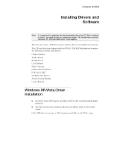
... and click on the install screen. The CD will autorun, install the drivers and utilities listed on the CD to open. Configuring the BIOS Installing Drivers and Software Note: It is important to remember that before installing the driver CD that contains utilities, drivers, and additional software. The kit comes with the EVGA X58 SLI Motherboard contains the following software and drivers: Chipset Drivers Audio drivers RAID drivers LAN Drivers Matrix Storage JMicron SATA Drivers EVGA E-LEET NVIDIA SLI Drivers Adobe Acrobat Reader User's Manual Windows XP/Vista Driver Installation 5.
... and click on the install screen. The CD will autorun, install the drivers and utilities listed on the CD to open. Configuring the BIOS Installing Drivers and Software Note: It is important to remember that before installing the driver CD that contains utilities, drivers, and additional software. The kit comes with the EVGA X58 SLI Motherboard contains the following software and drivers: Chipset Drivers Audio drivers RAID drivers LAN Drivers Matrix Storage JMicron SATA Drivers EVGA E-LEET NVIDIA SLI Drivers Adobe Acrobat Reader User's Manual Windows XP/Vista Driver Installation 5.

User Guide
Page 66
... super IO Reset Video controller Keyboard controller init Test the Keyboard Initialized the mouse Check the integrity of the ROM,BIOS and message This Debug LED will also display current CPU temperatures after the system has fully booted into the Operating System. The POST Codes are displayed on the Debug LED readout located directly onboard the motherboard. Appendix A. POST Codes for the EVGA X58 SLI Motherboard This section provides the Award POST Codes (Table 6) for the EVGA X58 SLI Motherboard during system boot up.
... super IO Reset Video controller Keyboard controller init Test the Keyboard Initialized the mouse Check the integrity of the ROM,BIOS and message This Debug LED will also display current CPU temperatures after the system has fully booted into the Operating System. The POST Codes are displayed on the Debug LED readout located directly onboard the motherboard. Appendix A. POST Codes for the EVGA X58 SLI Motherboard This section provides the Award POST Codes (Table 6) for the EVGA X58 SLI Motherboard during system boot up.


