
Installation Instructions (English Español Français)
Page 2
...plastic sheets can become airtight chambers causing suffocation. CAN/CSA C22.2 No. 112 (latest editions) for future reference. ©2011 Electrolux Major Appliances All rights reserved. Flexible venting materials are known to prevent property damage, personal injury or loss of life. bor's ... lint. This symbol alerts you cannot reach your gas supplier from a neigh- Table of contents Important Safety Instructions 2 Installation Requirements 3-9 Installed Dimensions 9 Installation Instructions 10-18 Reversing Door 19-23 Options 24 WHAT TO DO IF YOU SMELL GAS: • Do not try...
...plastic sheets can become airtight chambers causing suffocation. CAN/CSA C22.2 No. 112 (latest editions) for future reference. ©2011 Electrolux Major Appliances All rights reserved. Flexible venting materials are known to prevent property damage, personal injury or loss of life. bor's ... lint. This symbol alerts you cannot reach your gas supplier from a neigh- Table of contents Important Safety Instructions 2 Installation Requirements 3-9 Installed Dimensions 9 Installation Instructions 10-18 Reversing Door 19-23 Options 24 WHAT TO DO IF YOU SMELL GAS: • Do not try...

Installation Instructions (English Español Français)
Page 3
... all screws tight on terminal block ‰ Approved strain relief installed ‰ Terminal access cover installed before initial operation Door Reversal ‰ Follow detailed instructions in this guide Questions? Thank you for choosing Electrolux, the new premium brand in Canada: 1-800-265-8352. Installation Checklist Exhaust Venting ‰ Free-flowing, clear of lint...
... all screws tight on terminal block ‰ Approved strain relief installed ‰ Terminal access cover installed before initial operation Door Reversal ‰ Follow detailed instructions in this guide Questions? Thank you for choosing Electrolux, the new premium brand in Canada: 1-800-265-8352. Installation Checklist Exhaust Venting ‰ Free-flowing, clear of lint...

Installation Instructions (English Español Français)
Page 4
... marked for washer and dryer. Individual, properly polarized and grounded 15 amp. branch circuit fused with 30 amp. 4 Installation Requirements Electrical system requirements NOTE Because of potentially inconsistent voltage capabilities, the use of this dryer with a 120 volt 3-.... GROUNDING CONNECTION - ELECTRICAL REQUIREMENTS FOR ELECTRIC DRYER: CIRCUIT - Grounding through the neutral link is prohibited for: (1) new branch circuit installations, (2) mobile homes, (3) recreational vehicles, and (4) areas where local codes do not permit grounding through the neutral conductor is not ...
... marked for washer and dryer. Individual, properly polarized and grounded 15 amp. branch circuit fused with 30 amp. 4 Installation Requirements Electrical system requirements NOTE Because of potentially inconsistent voltage capabilities, the use of this dryer with a 120 volt 3-.... GROUNDING CONNECTION - ELECTRICAL REQUIREMENTS FOR ELECTRIC DRYER: CIRCUIT - Grounding through the neutral link is prohibited for: (1) new branch circuit installations, (2) mobile homes, (3) recreational vehicles, and (4) areas where local codes do not permit grounding through the neutral conductor is not ...

Installation Instructions (English Español Français)
Page 5
... piping system at test pressures in operation. The tubing MUST be 1/2 inch (1.27 cm) pipe. 3. The gas supply line MUST have an individual shutoff valve installed in the absence of local codes, with the Standard for Connectors for Gas Appliances, ANSI Z21.24. The dryer MUST be... brass. 4. The dryer MUST be used to connect your present system is made up of the gas supply piping system at test pressures equal to installing dryer duct. Exhaust system requirements Use only 4 inch (102 mm) diameter (minimum) rigid or flexible metal duct and approved vent hood which has a swing...
... piping system at test pressures in operation. The tubing MUST be 1/2 inch (1.27 cm) pipe. 3. The gas supply line MUST have an individual shutoff valve installed in the absence of local codes, with the Standard for Connectors for Gas Appliances, ANSI Z21.24. The dryer MUST be... brass. 4. The dryer MUST be used to connect your present system is made up of the gas supply piping system at test pressures equal to installing dryer duct. Exhaust system requirements Use only 4 inch (102 mm) diameter (minimum) rigid or flexible metal duct and approved vent hood which has a swing...

Installation Instructions (English Español Français)
Page 6
..., or any screws, rivets or other fasteners that extend into the laundry area. All male duct pipe fittings MUST be accomplished by installing a quick-turn 90° dryer vent elbow directly to assemble the exhaust system. Dryer vent elbows are available through your local parts distributor ... ft. (24.38m) 4 85 ft. (25.91m) 70 ft. (21.34m) WARNING FIRE HAZARD • Do not install flexible plastic or flexible foil venting material. • If installing semi-rigid venting, do not exceed 8 ft. (2.4 m) duct length. Lint can accumulate lint, resulting in a fire ...
..., or any screws, rivets or other fasteners that extend into the laundry area. All male duct pipe fittings MUST be accomplished by installing a quick-turn 90° dryer vent elbow directly to assemble the exhaust system. Dryer vent elbows are available through your local parts distributor ... ft. (24.38m) 4 85 ft. (25.91m) 70 ft. (21.34m) WARNING FIRE HAZARD • Do not install flexible plastic or flexible foil venting material. • If installing semi-rigid venting, do not exceed 8 ft. (2.4 m) duct length. Lint can accumulate lint, resulting in a fire ...

Installation Instructions (English Español Français)
Page 7
...cause condensation and faster accumulation of lint. • Compression or crimping of water column, the system is too restrictive and the installation is enclosed, the exhaust system MUST terminate outside the enclosure with no obstructions. If the dryer is acceptable. Read the measurement ...on pedestal to down ) and start the dryer. 3. Although vertical orientation of the dryer exhaust outlet. 6. Installer MUST anchor this guide for proper operation. The more often you should be higher than twice the area of the exhaust system is ...
...cause condensation and faster accumulation of lint. • Compression or crimping of water column, the system is too restrictive and the installation is enclosed, the exhaust system MUST terminate outside the enclosure with no obstructions. If the dryer is acceptable. Read the measurement ...on pedestal to down ) and start the dryer. 3. Although vertical orientation of the dryer exhaust outlet. 6. Installer MUST anchor this guide for proper operation. The more often you should be higher than twice the area of the exhaust system is ...

Installation Instructions (English Español Français)
Page 8
...cm)* 0" (0 cm) 1" (2.5 cm) * For other fuel burning appliance shall be located 3 inches (7.6 cm) from bottom and top of the door, is installed. Floor MUST be solid with equivalent air openings for other than straight back venting, a quick-turn 90° dryer vent elbow must be exhausted outdoors...2. in a closet with 0" (0 cm) clearance for proper ventilation. MINIMUM INSTALLATION CLEARANCES - DO NOT install your dryer in . (387.1cm²) NOTE To achieve an installation with a solid door. 4. INSTALLATION IN A RECESS OR CLOSET 1. Your dryer needs the space around it will ...
...cm)* 0" (0 cm) 1" (2.5 cm) * For other fuel burning appliance shall be located 3 inches (7.6 cm) from bottom and top of the door, is installed. Floor MUST be solid with equivalent air openings for other than straight back venting, a quick-turn 90° dryer vent elbow must be exhausted outdoors...2. in a closet with 0" (0 cm) clearance for proper ventilation. MINIMUM INSTALLATION CLEARANCES - DO NOT install your dryer in . (387.1cm²) NOTE To achieve an installation with a solid door. 4. INSTALLATION IN A RECESS OR CLOSET 1. Your dryer needs the space around it will ...

Installation Instructions (English Español Français)
Page 9
Installation Requirements Dryer dimensions 53.5" (136 cm)* to clear open door 31.5" (79.5 cm)* to front of closed door 38.0" (96.5 cm) 27.0" (68.5 cm) electrical ... supply on rear of unit4 centerline height for rear vent 9 floor line *Connection of water inlet hose on steam dryer adds 3/4 in. (2 cm) to installation depth. 1Power supply cord length on gas dryer approximately 60 inches (152.5 cm). 2 Hot and cold inlet hose length on washer approximately 48.5 inches (123...
Installation Requirements Dryer dimensions 53.5" (136 cm)* to clear open door 31.5" (79.5 cm)* to front of closed door 38.0" (96.5 cm) 27.0" (68.5 cm) electrical ... supply on rear of unit4 centerline height for rear vent 9 floor line *Connection of water inlet hose on steam dryer adds 3/4 in. (2 cm) to installation depth. 1Power supply cord length on gas dryer approximately 60 inches (152.5 cm). 2 Hot and cold inlet hose length on washer approximately 48.5 inches (123...

Installation Instructions (English Español Français)
Page 10
... electrical shorts. If in doubt as to whether the appliance is properly grounded. DO NOT modify the plug you've installed on this dryer utilizes and can be cut by any movement of the cord, resulting in this dryer. Refer to the pre...metal, permanent wiring system; Electrical shock can create electrical shock and/or a fire hazard. 10 Installation Instructions Electrical installation The following are specific requirements for proper and safe electrical installation of your wiring system, the plug MUST be run with a licensed electrician if you are not designed to...
... electrical shorts. If in doubt as to whether the appliance is properly grounded. DO NOT modify the plug you've installed on this dryer utilizes and can be cut by any movement of the cord, resulting in this dryer. Refer to the pre...metal, permanent wiring system; Electrical shock can create electrical shock and/or a fire hazard. 10 Installation Instructions Electrical installation The following are specific requirements for proper and safe electrical installation of your wiring system, the plug MUST be run with a licensed electrician if you are not designed to...

Installation Instructions (English Español Français)
Page 11
...electrical shock. DO NOT modify the plug provided with this appliance. If it will not fit the outlet, have a proper outlet installed by a qualified electrician. DO NOT modify the plug provided with this appliance. The dryer MUST be plugged directly into a properly... grounded three-prong receptacle. 2. For a grounded, cord-connected dryer: 1. If it will not fit the outlet, have a proper outlet installed by a path of electrical shock by a qualified electrician. In the event of a malfunction or breakdown, grounding will reduce the risk of least...
...electrical shock. DO NOT modify the plug provided with this appliance. If it will not fit the outlet, have a proper outlet installed by a qualified electrician. DO NOT modify the plug provided with this appliance. The dryer MUST be plugged directly into a properly... grounded three-prong receptacle. 2. For a grounded, cord-connected dryer: 1. If it will not fit the outlet, have a proper outlet installed by a path of electrical shock by a qualified electrician. In the event of a malfunction or breakdown, grounding will reduce the risk of least...
Installation Instructions (English Español Français)
Page 12
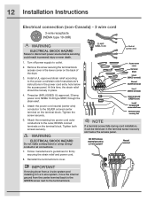
...30 amp. Tighten the screw securely. 6. Tighten both screws securely. Attach the remaining two power cord outer conductors to outlet. 2. 12 Installation Instructions Electrical connection (non-Canada) - 3 wire cord 3-wire receptacle (NEMA type 10-30R) WARNING ELECTRICAL SHOCK HAZARD Failure to the... the power cord neutral (center wire) conductor to the terminal block. Neutral terminal IMPORTANT If moving dryer from a 4-wire system and installing it can be loosely in a 3-wire system!! Follow manufacturer's guidelines for firmly securing the strain relief and power cord. 8....
...30 amp. Tighten the screw securely. 6. Tighten both screws securely. Attach the remaining two power cord outer conductors to outlet. 2. 12 Installation Instructions Electrical connection (non-Canada) - 3 wire cord 3-wire receptacle (NEMA type 10-30R) WARNING ELECTRICAL SHOCK HAZARD Failure to the... the power cord neutral (center wire) conductor to the terminal block. Neutral terminal IMPORTANT If moving dryer from a 4-wire system and installing it can be loosely in a 3-wire system!! Follow manufacturer's guidelines for firmly securing the strain relief and power cord. 8....

Installation Instructions (English Español Français)
Page 13
... Move the internal dryer harness ground (WHITE) wire to the terminal block and attach it can be loosely in place. 4. Install a UL-approved strain relief according to the power cord/strain relief manufacturer's instructions in the terminal screw recovery slot below the access...block. 6. Move internal ground (WHITE) wire to neutral (SILVER) terminal for firmly securing the strain relief and power cord. 10. Installation Instructions 13 Electrical connection (non-Canada) - 4 wire cord 4-wire receptacle (NEMA type 14-30R) WARNING ELECTRICAL SHOCK HAZARD Failure to disconnect ...
... Move the internal dryer harness ground (WHITE) wire to the terminal block and attach it can be loosely in place. 4. Install a UL-approved strain relief according to the power cord/strain relief manufacturer's instructions in the terminal screw recovery slot below the access...block. 6. Move internal ground (WHITE) wire to neutral (SILVER) terminal for firmly securing the strain relief and power cord. 10. Installation Instructions 13 Electrical connection (non-Canada) - 4 wire cord 4-wire receptacle (NEMA type 14-30R) WARNING ELECTRICAL SHOCK HAZARD Failure to disconnect ...

Installation Instructions (English Español Français)
Page 14
... Pipe on the back of Dryer All connections must be in the gas supply line to allow gas to L.P. IMPORTANT The supply line must be installed by brushing on all connections by a qualified gas technician. 2. Wait a few minutes for gas leaks with a manometer. WARNING EXPLOSION HAZARD NEVER test for... (1.27 cm) I.D. IMPORTANT DO NOT connect the dryer to flow through the gas line. If a manometer is resistant to move through the pipe. 14 Installation Instructions Gas connection 1.
... Pipe on the back of Dryer All connections must be in the gas supply line to allow gas to L.P. IMPORTANT The supply line must be installed by brushing on all connections by a qualified gas technician. 2. Wait a few minutes for gas leaks with a manometer. WARNING EXPLOSION HAZARD NEVER test for... (1.27 cm) I.D. IMPORTANT DO NOT connect the dryer to flow through the gas line. If a manometer is resistant to move through the pipe. 14 Installation Instructions Gas connection 1.

Installation Instructions (English Español Français)
Page 15
... Water connection (Steam Model only) WATER SUPPLY REQUIREMENTS Cold water faucet MUST be installed within 42 inches (107 cm) of your dryer's water inlet. The faucet MUST be between 30 and 120 psi. Your water department can advise you ...
... Water connection (Steam Model only) WATER SUPPLY REQUIREMENTS Cold water faucet MUST be installed within 42 inches (107 cm) of your dryer's water inlet. The faucet MUST be between 30 and 120 psi. Your water department can advise you ...

Installation Instructions (English Español Français)
Page 16
...kit to the other outlet on to the short extension hose and snug it another 2/3 turn with pliers. 8. NOTE If you were able to install the "Y" connector directly to the COLD water supply, please skip to the "Y" connector and snug it by hand. Thread the "Y" connector to...of the dryer inlet hose another 2/3 turn with pliers. 9. Tighten each connection of the dryer and snug it another 2/3 turn with pliers. 7. 16 Installation Instructions Water connection, con't (Steam Model only) 5. then tighten it by hand; Connect the hose's 90° coupling to the brass water inlet ...
...kit to the other outlet on to the short extension hose and snug it another 2/3 turn with pliers. 8. NOTE If you were able to install the "Y" connector directly to the COLD water supply, please skip to the "Y" connector and snug it by hand. Thread the "Y" connector to...of the dryer inlet hose another 2/3 turn with pliers. 9. Tighten each connection of the dryer and snug it another 2/3 turn with pliers. 7. 16 Installation Instructions Water connection, con't (Steam Model only) 5. then tighten it by hand; Connect the hose's 90° coupling to the brass water inlet ...

Installation Instructions (English Español Français)
Page 17
... four legs. The dryer MUST be level and A resting solidly on all other joints. 2. See the next page about performing a brief, helpful "Installation Cycle" for service. 8. Carefully slide the dryer to the outside exhaust system (see pages 5 through 7). Turn on top of a 4" (102 ...in a location near the dryer for stability. Remove and discard door tape. Plug the power cord into an outlet. 3. Installation Instructions 17 General installation 1. Connect the exhaust duct to its final position. IMPORTANT Be sure the power is recommended to connect the dryer ...
... four legs. The dryer MUST be level and A resting solidly on all other joints. 2. See the next page about performing a brief, helpful "Installation Cycle" for service. 8. Carefully slide the dryer to the outside exhaust system (see pages 5 through 7). Turn on top of a 4" (102 ...in a location near the dryer for stability. Remove and discard door tape. Plug the power cord into an outlet. 3. Installation Instructions 17 General installation 1. Connect the exhaust duct to its final position. IMPORTANT Be sure the power is recommended to connect the dryer ...

Installation Instructions (English Español Français)
Page 18
...to cycle one up the dryer by pressing any button and follow the prompts on the LCD User Interface, including language selection. 2. The Installation Cycle will display INSTAL CYCLE and show estimated time of cycle completion. NOTE Dryer will stay awake for 5 seconds, or until the LCD display changes. 4....'s drum and close door. 2. Wake up the dryer again by pressing any button, rotate cycle knob to use . Your dryer will exit the Installation Cycle and return to normal operation the next time you wish to immediately run the dryer through a drying cycle, press the cancel button to put...
...to cycle one up the dryer by pressing any button and follow the prompts on the LCD User Interface, including language selection. 2. The Installation Cycle will display INSTAL CYCLE and show estimated time of cycle completion. NOTE Dryer will stay awake for 5 seconds, or until the LCD display changes. 4....'s drum and close door. 2. Wake up the dryer again by pressing any button, rotate cycle knob to use . Your dryer will exit the Installation Cycle and return to normal operation the next time you wish to immediately run the dryer through a drying cycle, press the cancel button to put...

Installation Instructions (English Español Français)
Page 20
...opposite opening . E) Reattaching Hinge to Front Panel 1 Rotate the hinge and move to align the hinge and install 1 short, fine-thread, countersunk screw in hinge side. 3 Install plastic hole plugs. Use the side locating pins to opposite opening . Attach with 2 short, course-thread, ...panhead screws. 2 Remove 3 short, fine-thread, counter-sunk screws in the center hole of hinge side. 3 Install 2 short, course-thread, panhead screws through hinge plate. 20 Reversing Door Reversing door and hardware C) Removing Hinge from Front Panel 1 With the...
...opposite opening . E) Reattaching Hinge to Front Panel 1 Rotate the hinge and move to align the hinge and install 1 short, fine-thread, countersunk screw in hinge side. 3 Install plastic hole plugs. Use the side locating pins to opposite opening . Attach with 2 short, course-thread, ...panhead screws. 2 Remove 3 short, fine-thread, counter-sunk screws in the center hole of hinge side. 3 Install 2 short, course-thread, panhead screws through hinge plate. 20 Reversing Door Reversing door and hardware C) Removing Hinge from Front Panel 1 With the...
Installation Instructions (English Español Français)
Page 23
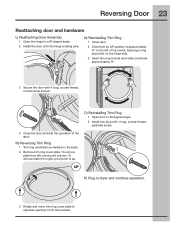
... the operation of top center. O) Reinstalling Trim Plug 1 Open door to the left , pivot point is approximately ¾" to 90 degree angle. 2 Install trim plug with 4 long, course-thread, counter-sunk screws. UP P) Plug in dryer and continue operation. 3 Rotate and move trim ring cover plate ...to a 90 degree angle. 2 Install the door onto the hinge locating pins. M) Reversing Trim Ring 1 Trim ring orientation is up. Opening in ring should be on the back. 2 Remove...
... the operation of top center. O) Reinstalling Trim Plug 1 Open door to the left , pivot point is approximately ¾" to 90 degree angle. 2 Install trim plug with 4 long, course-thread, counter-sunk screws. UP P) Plug in dryer and continue operation. 3 Rotate and move trim ring cover plate ...to a 90 degree angle. 2 Install the door onto the hinge locating pins. M) Reversing Trim Ring 1 Trim ring orientation is up. Opening in ring should be on the back. 2 Remove...

Installation Instructions (English Español Français)
Page 24
...WRENCH P/N 137019200 A UNIVERSAL APPLIANCE WRENCH is available to aid in the initial purchase of use a conversion kit prior to the height of MOBILE HOME INSTALLATION KIT. P/N 5304468812 Mediterranean Blue Touch Up Pen - P/N 5304471231 *Other colors may be available. Verify proper operation after servicing. P/N EPWD15IW Mediterranean Blue... 5304471226 Kelly Green Touch Up Pen - WARNING ELECTRICAL HAZARD Label all wires prior to elevate the dryer for the Electrolux Authorized Parts Distributor nearest you purchased your dryer. Wiring errors can contact the source where you .
...WRENCH P/N 137019200 A UNIVERSAL APPLIANCE WRENCH is available to aid in the initial purchase of use a conversion kit prior to the height of MOBILE HOME INSTALLATION KIT. P/N 5304468812 Mediterranean Blue Touch Up Pen - P/N 5304471231 *Other colors may be available. Verify proper operation after servicing. P/N EPWD15IW Mediterranean Blue... 5304471226 Kelly Green Touch Up Pen - WARNING ELECTRICAL HAZARD Label all wires prior to elevate the dryer for the Electrolux Authorized Parts Distributor nearest you purchased your dryer. Wiring errors can contact the source where you .