

Use and Care Guide
Page 1
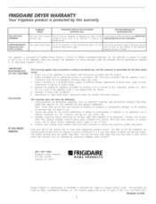
... self-addressed PRODUCT REGISTRATION CARD should be filled in completely, signed and returned. This owner's guide will explain proper operation and care. Model Number Serial Number Date of the door opening. P/N 134420700A (0412) Keep these numbers for choosing this dryer. [] [] [] al DRYER Table of Contents Dryer Warranty 2 IMPORTANT SAFETY fNSTRUCTIONS 3-4 Drying Procedures 5-6 Common Drying Problems 6 Care and Cleaning 7 Avoid Service Checklist 8 www.frigidaire.com Product Registration Thank you for future reference.
... self-addressed PRODUCT REGISTRATION CARD should be filled in completely, signed and returned. This owner's guide will explain proper operation and care. Model Number Serial Number Date of the door opening. P/N 134420700A (0412) Keep these numbers for choosing this dryer. [] [] [] al DRYER Table of Contents Dryer Warranty 2 IMPORTANT SAFETY fNSTRUCTIONS 3-4 Drying Procedures 5-6 Common Drying Problems 6 Care and Cleaning 7 Avoid Service Checklist 8 www.frigidaire.com Product Registration Thank you for future reference.
Use and Care Guide
Page 2
Proper use ol the appliance in accordance with instructions provided with the product, 2, Proper installation by an authorized servicer in accordance with instructions provided with the appliance and in accordance with all local plumbing, electrical and/or gas codes. 3, Proper connection to a grounded power supply of sufficient voltage, replacement of blown fuses, repair of loose connections or defects in your bill of sale, delivery slip...
Proper use ol the appliance in accordance with instructions provided with the product, 2, Proper installation by an authorized servicer in accordance with instructions provided with the appliance and in accordance with all local plumbing, electrical and/or gas codes. 3, Proper connection to a grounded power supply of sufficient voltage, replacement of blown fuses, repair of loose connections or defects in your bill of sale, delivery slip...

Use and Care Guide
Page 3
... these areas could result in these items on or near dryer at any electrical switch; Use Air Fluff (No Heat) only. See Care and Cleaning, page 7. Pedestal A pedestal accessory, Model No. Keep area around the exhaust opening and surrounding areas free from a neighbor's phone. Follow the gas supplier's instructions. Always read and obey all occupants. This is blocked, damaged or missing. To reduce tile risk of fire...
... these areas could result in these items on or near dryer at any electrical switch; Use Air Fluff (No Heat) only. See Care and Cleaning, page 7. Pedestal A pedestal accessory, Model No. Keep area around the exhaust opening and surrounding areas free from a neighbor's phone. Follow the gas supplier's instructions. Always read and obey all occupants. This is blocked, damaged or missing. To reduce tile risk of fire...

Use and Care Guide
Page 4
... the grounding prong from electrical power cord. Use only authorized factory parts. • Donottamperwith controls. • Do not install or store the dryer where it checked and reinstalled by an authorized servicer unless specifically recommended in this Owner's Guide. A service technician must be performed by a qualified service person. Failure to prevent accidental entrapment. Children might use an adaptor plug or extension cord or remove grounding prong from this Use and Care Guide are packed...
... the grounding prong from electrical power cord. Use only authorized factory parts. • Donottamperwith controls. • Do not install or store the dryer where it checked and reinstalled by an authorized servicer unless specifically recommended in this Owner's Guide. A service technician must be performed by a qualified service person. Failure to prevent accidental entrapment. Children might use an adaptor plug or extension cord or remove grounding prong from this Use and Care Guide are packed...
Use and Care Guide
Page 5
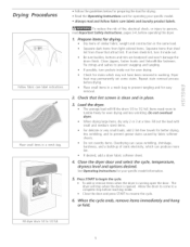
... even drying and less wrinkling. Fill out the load with small and medium sized items. For delicate or very small loads, add 2 lint-free towels for better drying, less wrinkling, and to prevent tangling and for your specific model. • Always read Important Safety Instructions, pages 3-4, before drying. See Operating btstrucdons for easy removal. . Press START to a complete stop when the door is opened. Allow the drum to come to...
... even drying and less wrinkling. Fill out the load with small and medium sized items. For delicate or very small loads, add 2 lint-free towels for better drying, less wrinkling, and to prevent tangling and for your specific model. • Always read Important Safety Instructions, pages 3-4, before drying. See Operating btstrucdons for easy removal. . Press START to a complete stop when the door is opened. Allow the drum to come to...
Use and Care Guide
Page 6
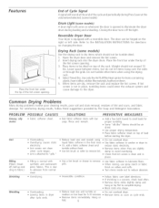
... down. 5. Reversible Dryer Door Your dryer is equipped with synthetic and permanent press fabrics_ This is opened to illuminate the dryer drum during PressSaver at medium or low heat for directions on changing the door. Drying Rack (some models) A drum light will come on whenever the door is due to abrasion from normal wear. Place items to be air dried , Use proper drying temperature Place fabric softener sheet on top of load before starting the dryer. Do...
... down. 5. Reversible Dryer Door Your dryer is equipped with synthetic and permanent press fabrics_ This is opened to illuminate the dryer drum during PressSaver at medium or low heat for directions on changing the door. Drying Rack (some models) A drum light will come on whenever the door is due to abrasion from normal wear. Place items to be air dried , Use proper drying temperature Place fabric softener sheet on top of load before starting the dryer. Do...
Use and Care Guide
Page 7
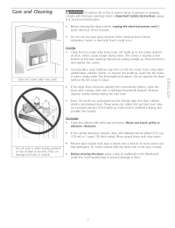
... operate tile dryer without the lint screen in 1 quart (.95 liter) water]. Every 18 months an authorized servicer should clean the dryer cabinet interior and exhaust duct. Hazardous fumes or electrical shock could result in the screen restricts air flow, which causes longer drying times. The screen is located at any type spray cleanser when cleaning dryer interior. Do not store or place laundry products on the lint screen from using dryeradded fabric softener sheets. Care...
... operate tile dryer without the lint screen in 1 quart (.95 liter) water]. Every 18 months an authorized servicer should clean the dryer cabinet interior and exhaust duct. Hazardous fumes or electrical shock could result in the screen restricts air flow, which causes longer drying times. The screen is located at any type spray cleanser when cleaning dryer interior. Do not store or place laundry products on the lint screen from using dryeradded fabric softener sheets. Care...

Use and Care Guide
Page 8
... drum, Always remove foreign objects from pockets before [aundering_ Remove objects from the dryer lint screen before drying to prevent scratching and damage to support the burner flame (gas models)_ LP gas supply tank is restored Drying cycle takes too long, outsideofthedryerfeelstoo hot or smells hot. There are inside of material securely around ornaments before starting each cycle_ Exhaust duct must not exceed length listed in wall outlet Reset circuit breaker or replace fuse_ Make sure electrical line...
... drum, Always remove foreign objects from pockets before [aundering_ Remove objects from the dryer lint screen before drying to prevent scratching and damage to support the burner flame (gas models)_ LP gas supply tank is restored Drying cycle takes too long, outsideofthedryerfeelstoo hot or smells hot. There are inside of material securely around ornaments before starting each cycle_ Exhaust duct must not exceed length listed in wall outlet Reset circuit breaker or replace fuse_ Make sure electrical line...
Installation Instructions
Page 2
...Unpacking ...Reversing Door Swing ...Electrical Installation ...Grounding Requirements ...Electrical Connections--3-wire ...Electrical Connections--4-wire ...Gas Connection ...General Installation ...Replacement Parts ...Espahol ... 2 3 3-4 4-5 5 6 7 7 7-9 I0 I0 11 11 12 12 12 13-24 SAFETY INSTRUCTIONS Before beginning installation, carefully read these instructions near the Dryer after installation for HOME USE only. do not use gasoline or other flammable vapors and liquid in your safety the information in this or any electrical switch; Rigid or flexible metal 4 inch (10.2 cm) duct...
...Unpacking ...Reversing Door Swing ...Electrical Installation ...Grounding Requirements ...Electrical Connections--3-wire ...Electrical Connections--4-wire ...Gas Connection ...General Installation ...Replacement Parts ...Espahol ... 2 3 3-4 4-5 5 6 7 7 7-9 I0 I0 11 11 12 12 12 13-24 SAFETY INSTRUCTIONS Before beginning installation, carefully read these instructions near the Dryer after installation for HOME USE only. do not use gasoline or other flammable vapors and liquid in your safety the information in this or any electrical switch; Rigid or flexible metal 4 inch (10.2 cm) duct...

Installation Instructions
Page 3
... 3-wire power cord. See ELECTRICAL CONNECTIONS FOR A 4-WIRE SYSTEM. (Canada - 4-wire power supply cord is installed on the same circuit. Ensure the present duct is prohibited for washers and dryers, and DO NOT operate a washer and a dryer on dryer.) EXHAUST SYSTEM REQUIREMENTS Use only 4 inch (10.2 cm) diameter (minimum) rigid or flexible metal duct and approved vent hood which has a swing-out damper(s) that open end spade lug connectors with a rigid or flexible metal duct. branch circuit fused...
... 3-wire power cord. See ELECTRICAL CONNECTIONS FOR A 4-WIRE SYSTEM. (Canada - 4-wire power supply cord is installed on the same circuit. Ensure the present duct is prohibited for washers and dryers, and DO NOT operate a washer and a dryer on dryer.) EXHAUST SYSTEM REQUIREMENTS Use only 4 inch (10.2 cm) diameter (minimum) rigid or flexible metal duct and approved vent hood which has a swing-out damper(s) that open end spade lug connectors with a rigid or flexible metal duct. branch circuit fused...
Installation Instructions
Page 4
... well as increasing drying times. EXHAUST DIRECTION All dryers shipped from the factory are kept or stored. On gas dryers, exhausting can be to terminate the duct outdoors, and seal all joints with the kit. Follow the instructions supplied with duct tape. EXHAUST DUCT LOCATING DIMENSIONS I/ I . Installation MUSTconform with exhaust system. The gas supply line MUSThave an individual shutoff valve. Do not screen the exhaust ends of the vent system, nor use any concealed space of...
... well as increasing drying times. EXHAUST DIRECTION All dryers shipped from the factory are kept or stored. On gas dryers, exhausting can be to terminate the duct outdoors, and seal all joints with the kit. Follow the instructions supplied with duct tape. EXHAUST DUCT LOCATING DIMENSIONS I/ I . Installation MUSTconform with exhaust system. The gas supply line MUSThave an individual shutoff valve. Do not screen the exhaust ends of the vent system, nor use any concealed space of...

Installation Instructions
Page 5
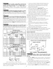
... be exhausted outdoors. 2. MINIMUM INSTALLATION CLEARANCES - Air openings are required to the dryer. 6. LOCATION OF YOUR DRYER DO NOT INSTALL YOUR DRYER: 1. Inches (cm) SIDES REAR TOP FRONT Alcove 0(0cm) 0(0cm) Closet 0 (0 cm) 0 (0 cm) 1 (2.54 cm) Closet door ventilation required: 2 Iouvered openings each 60 square inches (387 square centimeters) -- 3 inches (7.6 cm) from the gas supply piping system during any pressure testing of I /2 psig (3.45 kPa). 7. Your dryer needs...
... be exhausted outdoors. 2. MINIMUM INSTALLATION CLEARANCES - Air openings are required to the dryer. 6. LOCATION OF YOUR DRYER DO NOT INSTALL YOUR DRYER: 1. Inches (cm) SIDES REAR TOP FRONT Alcove 0(0cm) 0(0cm) Closet 0 (0 cm) 0 (0 cm) 1 (2.54 cm) Closet door ventilation required: 2 Iouvered openings each 60 square inches (387 square centimeters) -- 3 inches (7.6 cm) from the gas supply piping system during any pressure testing of I /2 psig (3.45 kPa). 7. Your dryer needs...

Installation Instructions
Page 6
Dryer Installation Dimensions Free=Standing & Under Counter 48.5" To clear open door (123.19cm) Electrical supply on rear of unit / 0 o ,'_,_ # l Gas supply pipe \ on rear of cabinet(71.76cm) 28.75" to clear knobs (73.03cm) 29.5" to clear door handle 49" to front of unit LU O T "_i• 41.00" (104.14cm) Center line height for rear, right, left vent 4.375" To side exhausts (5. 72 cm...
Dryer Installation Dimensions Free=Standing & Under Counter 48.5" To clear open door (123.19cm) Electrical supply on rear of unit / 0 o ,'_,_ # l Gas supply pipe \ on rear of cabinet(71.76cm) 28.75" to clear knobs (73.03cm) 29.5" to clear door handle 49" to front of unit LU O T "_i• 41.00" (104.14cm) Center line height for rear, right, left vent 4.375" To side exhausts (5. 72 cm...

Installation Instructions
Page 7
... mobile home) using metal ducting that attach the hinge to remove all parts for Mobile Homes. Installation MUST conform to the mobile home structure. 3. For best results, start by only removing one screw per hinge. MOBILE HOME INSTALLATION I. The dryer is preferred. 2. This dryer MUST be not less than twice the area of the dryer exhaust outlet. 4. L REVERSING DOOR SWING Solid Door Reversing Instructions: 1. Open door and remove four (4) plugs in not...
... mobile home) using metal ducting that attach the hinge to remove all parts for Mobile Homes. Installation MUST conform to the mobile home structure. 3. For best results, start by only removing one screw per hinge. MOBILE HOME INSTALLATION I. The dryer is preferred. 2. This dryer MUST be not less than twice the area of the dryer exhaust outlet. 4. L REVERSING DOOR SWING Solid Door Reversing Instructions: 1. Open door and remove four (4) plugs in not...

Installation Instructions
Page 8
... panel or door. Remove all . Window Door Reversal Instructions Figure 1 1.Open door and remove four (4) plugs in not scratching paint on the front panel. Pull handle away from door. Apply moderate pressure downward and rotate lens 180 degrees so that door handle screws were just removed. Then only loosen the two remaining screws while firmly holding door to prevent damage to door. Figure 3 3. Install two (2) hole plugs from...
... panel or door. Remove all . Window Door Reversal Instructions Figure 1 1.Open door and remove four (4) plugs in not scratching paint on the front panel. Pull handle away from door. Apply moderate pressure downward and rotate lens 180 degrees so that door handle screws were just removed. Then only loosen the two remaining screws while firmly holding door to prevent damage to door. Figure 3 3. Install two (2) hole plugs from...

Installation Instructions
Page 9
...panel door opening where hinges were originally installed. Remove striker and discard. 16. Figure 9 9. Install four (4) plugs into handle bosses. (Figure 12). 19. Insert transition plugs through lens. (Figure 8). Remove four (4) screws from side of door opposite of the door, position the door near the door opening...Install four (4) screws securing hinge to door assembly in the new location, take note to the lower hinge. Onl uired on doors with holes in transition ring where handle was just removed. 17. Install four (4) screws into transition ring. (FigurelO) Flip door,...
...panel door opening where hinges were originally installed. Remove striker and discard. 16. Figure 9 9. Install four (4) plugs into handle bosses. (Figure 12). 19. Insert transition plugs through lens. (Figure 8). Remove four (4) screws from side of door opposite of the door, position the door near the door opening...Install four (4) screws securing hinge to door assembly in the new location, take note to the lower hinge. Onl uired on doors with holes in transition ring where handle was just removed. 17. Install four (4) screws into transition ring. (FigurelO) Flip door,...
Installation Instructions
Page 10
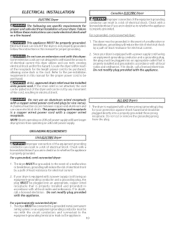
... or remove the grounding prong from the plug. Check with this manual for proper grounding. 1. Do not modify plug provided with a copper wired receptacle. If tile strain relief is properly grounded. Do not modify plug provided with the circuit conductors and connected to be properly grounded. Do not use an extension cord with a licensed electrician if you are in a risk of the dryer...
... or remove the grounding prong from the plug. Check with this manual for proper grounding. 1. Do not modify plug provided with a copper wired receptacle. If tile strain relief is properly grounded. Do not modify plug provided with the circuit conductors and connected to be properly grounded. Do not use an extension cord with a licensed electrician if you are in a risk of the dryer...

Installation Instructions
Page 11
... turn . 10.Reinstall the terminal block access cover. 11 Printed in the entry hole of the dryer upper corner. 2. Tighten the screws securing the cord restraint firmly against 7. WIRE SYSTEM USA ELECTR/CDryer l 1. Install a U.L approved strain relief in U.S.A. Tighten the screw securely. 5. power cord, NEMA 10-30 type SRDT,through the strain relief. 4. Remove the screws securing the terminal block access cover and the strain relief mounting bracket located...
... turn . 10.Reinstall the terminal block access cover. 11 Printed in the entry hole of the dryer upper corner. 2. Tighten the screws securing the cord restraint firmly against 7. WIRE SYSTEM USA ELECTR/CDryer l 1. Install a U.L approved strain relief in U.S.A. Tighten the screw securely. 5. power cord, NEMA 10-30 type SRDT,through the strain relief. 4. Remove the screws securing the terminal block access cover and the strain relief mounting bracket located...
Installation Instructions
Page 12
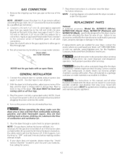
.... VALVE OPEN I .D. Connect the exhaust duct to cover every possible condition and situation that nothing (such as boxes, clothing, etc.) obstructs the flow of the dryer. With the dryer in your dryer, call 1-800-944-9044, or visit our website, www.frigidaire.com, for a connection. Run the dryer through a cycle check for service. 12 NOTE: Awiring diagram is off . Connect a I/2 inch (1.27 cm) I GAS FLOW POSITION REPLACEMENT PARTS Pedestal A pedestal accessory, Model No. Open the shutoff valve in...
.... VALVE OPEN I .D. Connect the exhaust duct to cover every possible condition and situation that nothing (such as boxes, clothing, etc.) obstructs the flow of the dryer. With the dryer in your dryer, call 1-800-944-9044, or visit our website, www.frigidaire.com, for a connection. Run the dryer through a cycle check for service. 12 NOTE: Awiring diagram is off . Connect a I/2 inch (1.27 cm) I GAS FLOW POSITION REPLACEMENT PARTS Pedestal A pedestal accessory, Model No. Open the shutoff valve in...


