

Owner Manual
Page 1
...: 131113 Questions, problems, missing parts: Before returning to the store call Emerson Electric Customer Service 8 a.m. - 6 p.m., Eastern, Monday-Friday 1-800-654-3545 www.emersonfans.com Form No. Model No.: CF4801 and CF4501 BP7447-1 U.L. READ AND SAVE THESE INSTRUCTIONS Fan Blades Not Included PREMIUM™ SELECT CROWN™ SELECT Ceiling Fan Owner's Manual Model Numbers CF4801AB00 CF4801AP00 CF4801BS00 CF4801GBZ00 CF4801GES00 CF4801ORB00 CF4801SW00 CF4801VNB00 CF4801WW00 Model Numbers CF4501AP00 CF4501GBZ00 CF4501GES00 CF4501VNB00 Net Weight: 23...
...: 131113 Questions, problems, missing parts: Before returning to the store call Emerson Electric Customer Service 8 a.m. - 6 p.m., Eastern, Monday-Friday 1-800-654-3545 www.emersonfans.com Form No. Model No.: CF4801 and CF4501 BP7447-1 U.L. READ AND SAVE THESE INSTRUCTIONS Fan Blades Not Included PREMIUM™ SELECT CROWN™ SELECT Ceiling Fan Owner's Manual Model Numbers CF4801AB00 CF4801AP00 CF4801BS00 CF4801GBZ00 CF4801GES00 CF4801ORB00 CF4801SW00 CF4801VNB00 CF4801WW00 Model Numbers CF4501AP00 CF4501GBZ00 CF4501GES00 CF4501VNB00 Net Weight: 23...
Owner Manual
Page 2
... for Installation 1. When the service disconnecting means cannot be sure electricity is turned off the power to the service panel. 1. outlet boxes listed as a tag, to the ceiling fan before installation. If you have come to a complete stop. How to Wire Your Ceiling Fan 9 6. Maintenance 11 10. Read your owner's manual carefully and keep it for use with an isolating wall control/switch. Additional Safety Instructions for Fan Support of wiring your fan installed by Emerson Electric Co...
... for Installation 1. When the service disconnecting means cannot be sure electricity is turned off the power to the service panel. 1. outlet boxes listed as a tag, to the ceiling fan before installation. If you have come to a complete stop. How to Wire Your Ceiling Fan 9 6. Maintenance 11 10. Read your owner's manual carefully and keep it for use with an isolating wall control/switch. Additional Safety Instructions for Fan Support of wiring your fan installed by Emerson Electric Co...
Owner Manual
Page 3
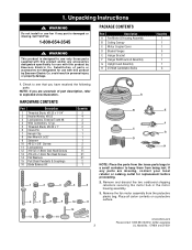
PACKAGE CONTENTS Part Description A Fan Motor & Housing Assembly B Ceiling Canopy C Motor Coupler Cover D Blades Flanges E Hanger Bracket F Hanger Ball/Downrod Assembly G Uplight Lead Assembly H 25-Watt Candelabra Bulbs Quantity 1 1 1 5 1 1 1 3 1. Check to keep them from being lost. HARDWARE CONTENTS Part Description 1 Threaded Studs, #8-32 x 1-1/4" 2 Knurled Knobs, #8-32 3 Lockwashers, External Tooth #8 4 Wire Connectors, 12 ga. 5 Threaded Studs, #8-32 x 1" 6 Clevis Pin 7 Hairpin Clip 8 Hex Wrench, 5/32" 9 Setscrew 10 #8-32 x 3/8" Screws 11 Lockwashers 12 #10-32...
PACKAGE CONTENTS Part Description A Fan Motor & Housing Assembly B Ceiling Canopy C Motor Coupler Cover D Blades Flanges E Hanger Bracket F Hanger Ball/Downrod Assembly G Uplight Lead Assembly H 25-Watt Candelabra Bulbs Quantity 1 1 1 5 1 1 1 3 1. Check to keep them from being lost. HARDWARE CONTENTS Part Description 1 Threaded Studs, #8-32 x 1-1/4" 2 Knurled Knobs, #8-32 3 Lockwashers, External Tooth #8 4 Wire Connectors, 12 ga. 5 Threaded Studs, #8-32 x 1" 6 Clevis Pin 7 Hairpin Clip 8 Hex Wrench, 5/32" 9 Setscrew 10 #8-32 x 3/8" Screws 11 Lockwashers 12 #10-32...

Owner Manual
Page 4
... against possible electrical shock. ! Consult a qualified electrician if in accordance with outlet box. 1. Wire Size A.W.G. 14 12 Your Emerson ceiling fan comes supplied with ground) of following size: Installed Wire Length Up to Assemble, Install, Operate and Maintain Your Ceiling Fan Tools Needed for Assembly One Phillips head screwdriver One wire stripper One stepladder Materials Wiring outlet box and box connectors must be a 3-conductor (2-wire with a Fan/Light Remote Control which consists of a receiver mounted inside the ceiling cover of 120...
... against possible electrical shock. ! Consult a qualified electrician if in accordance with outlet box. 1. Wire Size A.W.G. 14 12 Your Emerson ceiling fan comes supplied with ground) of following size: Installed Wire Length Up to Assemble, Install, Operate and Maintain Your Ceiling Fan Tools Needed for Assembly One Phillips head screwdriver One wire stripper One stepladder Materials Wiring outlet box and box connectors must be a 3-conductor (2-wire with a Fan/Light Remote Control which consists of a receiver mounted inside the ceiling cover of 120...
Owner Manual
Page 5
... hairpin clip through the hole near the end of the motor is not sufficient. WARNING It is critical that the clevis pin in accordance with National and Local codes and the ceiling fan must go through the downrod. Model No.: CF4801 and CF4501 WARNING Turning off at the main fuse box before wiring. All wiring must be properly installed to make sure the...
... hairpin clip through the hole near the end of the motor is not sufficient. WARNING It is critical that the clevis pin in accordance with National and Local codes and the ceiling fan must go through the downrod. Model No.: CF4801 and CF4501 WARNING Turning off at the main fuse box before wiring. All wiring must be properly installed to make sure the...
Owner Manual
Page 6
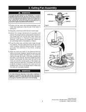
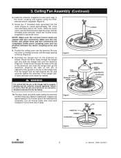
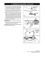
... motor coupling cover and not pinched between the motor coupling cover and motor. 8. Figure 3 WIRE CONNECTORS RED LEAD BROWN LEAD MOTOR Figure 4 DOWNROD SETSCREW KNURLED KNOB MOTOR COUPLING COVER WIRE CONNECTOR YELLOW LEADS 1" THREADED STUD 7/8" PIN HANGER BALL DOWNROD CEILING COVER SETSCREW Figure 5 6 U.L. Ceiling Fan Assembly (Continued) 6. Screw two 1" threaded studs (provided) into the motor (Figure 4). Route the motor leads through the holes at the top (Figure 5). 9. The blue, black and white leads exiting the downrod are capped...
... motor coupling cover and not pinched between the motor coupling cover and motor. 8. Figure 3 WIRE CONNECTORS RED LEAD BROWN LEAD MOTOR Figure 4 DOWNROD SETSCREW KNURLED KNOB MOTOR COUPLING COVER WIRE CONNECTOR YELLOW LEADS 1" THREADED STUD 7/8" PIN HANGER BALL DOWNROD CEILING COVER SETSCREW Figure 5 6 U.L. Ceiling Fan Assembly (Continued) 6. Screw two 1" threaded studs (provided) into the motor (Figure 4). Route the motor leads through the holes at the top (Figure 5). 9. The blue, black and white leads exiting the downrod are capped...
Owner Manual
Page 7
... flange to the motor hub, working in a clockwise sequence. Use the 10 round recessed holes in the motor hub marked with "5" and install the five blade assemblies (ordered separately) in the same way. NOTE: Make sure wires are installing. 12. Model No.: CF4801 and CF4501 Do not tighten completely at this procedure could result in a clockwise sequence. Failure to secure cover (Figure 8). Ceiling Fan Assembly (Continued) 11...
... flange to the motor hub, working in a clockwise sequence. Use the 10 round recessed holes in the motor hub marked with "5" and install the five blade assemblies (ordered separately) in the same way. NOTE: Make sure wires are installing. 12. Model No.: CF4801 and CF4501 Do not tighten completely at this procedure could result in a clockwise sequence. Failure to secure cover (Figure 8). Ceiling Fan Assembly (Continued) 11...

Owner Manual
Page 8
... electricity is turned off wall switch is not sufficient. WARNING Hanger bracket must be replaced. If bracket and/or outlet box are not acceptable for fan support and may need to be properly grounded as "Acceptable for support of 22.7 kg. (50 lbs.) or less", and use screws supplied with tab on the hanger bracket that was just attached to Hang Your Ceiling Fan ! Figure 11 OUTLET BOX HANGER BRACKET HANGER BALL/ DOWNROD ASSEMBLY ! outlet box listed...
... electricity is turned off wall switch is not sufficient. WARNING Hanger bracket must be replaced. If bracket and/or outlet box are not acceptable for fan support and may need to be properly grounded as "Acceptable for support of 22.7 kg. (50 lbs.) or less", and use screws supplied with tab on the hanger bracket that was just attached to Hang Your Ceiling Fan ! Figure 11 OUTLET BOX HANGER BRACKET HANGER BALL/ DOWNROD ASSEMBLY ! outlet box listed...
Owner Manual
Page 9
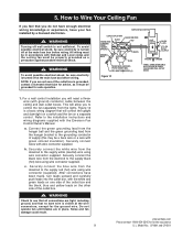
EMERSON FAN CONTROL LISTED OUTLET BOX GREEN WIRE (GROUND) FROM HANGER BRACKET BLACK GROUND WIRE BLACK FAN WIRE RED WHITE BLUE GREEN WIRE (GROUND) FROM HANGER BALL LISTED WIRE CONNECTOR (4) Figure 12 LIGHT CONTROL WHT. Figure 12 is visible at the wire connectors, except for safe operation. Securely connect wires with the Emerson Fan Control Owner's Manual. WARNING Check to control the fan separately from the lights. All wiring must be grounded for the ground wire. NOTE: If you feel that will need a threewire (with green colored insulation...
EMERSON FAN CONTROL LISTED OUTLET BOX GREEN WIRE (GROUND) FROM HANGER BRACKET BLACK GROUND WIRE BLACK FAN WIRE RED WHITE BLUE GREEN WIRE (GROUND) FROM HANGER BALL LISTED WIRE CONNECTOR (4) Figure 12 LIGHT CONTROL WHT. Figure 12 is visible at the wire connectors, except for safe operation. Securely connect wires with the Emerson Fan Control Owner's Manual. WARNING Check to control the fan separately from the lights. All wiring must be grounded for the ground wire. NOTE: If you feel that will need a threewire (with green colored insulation...
Owner Manual
Page 10
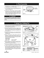
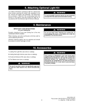
... in the hanger bracket. 2. When controlled by a wall switch, check the operation of the pipe. 1-1/4" THREADED STUD KNURLED KNOB Figure 13 ! The blades will turn the fan on switch cup, to stop turning. Screw the two 1-1/4" threaded studs (provided) into the uplight sockets on the 2-position accent light control pull chain. (This switch has the shorter pull chain.) The speed control operating sequence is now complete. Final Assembly 1. CEILING COVER LOCKWASHERS (2) 7. Screw three 25...
... in the hanger bracket. 2. When controlled by a wall switch, check the operation of the pipe. 1-1/4" THREADED STUD KNURLED KNOB Figure 13 ! The blades will turn the fan on switch cup, to stop turning. Screw the two 1-1/4" threaded studs (provided) into the uplight sockets on the 2-position accent light control pull chain. (This switch has the shorter pull chain.) The speed control operating sequence is now complete. Final Assembly 1. CEILING COVER LOCKWASHERS (2) 7. Screw three 25...
Owner Manual
Page 11
... Optional Light Kit To install an Emerson accessory light kit, remove the three screws securing the switch cup assembly to finish. ! When cleaning, use with this product by Emerson Electric Co. It could result in fire, shock and personal injury. ! Ceiling Fan Light Kits (see store or catalog). ! WARNING Do not use with the Emerson light kit Owner's Manual. ! Ceiling Fan/Light Controls (see store or catalog). 4. WARNING This product is turned off at the main service box before wiring. 9. WARNING The use...
... Optional Light Kit To install an Emerson accessory light kit, remove the three screws securing the switch cup assembly to finish. ! When cleaning, use with this product by Emerson Electric Co. It could result in fire, shock and personal injury. ! Ceiling Fan Light Kits (see store or catalog). ! WARNING Do not use with the Emerson light kit Owner's Manual. ! Ceiling Fan/Light Controls (see store or catalog). 4. WARNING This product is turned off at the main service box before wiring. 9. WARNING The use...
Owner Manual
Page 13
Description Hanger Pack, containing: 1 Bracket, Hanger (1) 2 Hanger Ball Assembly (1) 3 Downrod (1) 6 Cover, Ceiling 7 Hub, Rubber 8 Blade Assembly (Full set for one fan) 10 Switch Cup 13 Cover, Motor 23 Motor Parts Bag, containing: 4 Pin, Clevis (1) 5 Clip, Hairpin (1) 11 Coupling (2) 12 Pendant (2) 14 Wire Connector (3) 15 Wrench, Setscrew (1) 16 Stud, Threaded, 1-1/4" (2) 17 Lockwasher (2) 18 Knob, Knurled (4) 19 Screw, 10-32 x 18mm (11) 20 Screw, 8-32 x 3/8" (2) 21 Screw, #10-24 x 14mm (21) 22 Washer, Flat (21) 27 Setscrew...
Description Hanger Pack, containing: 1 Bracket, Hanger (1) 2 Hanger Ball Assembly (1) 3 Downrod (1) 6 Cover, Ceiling 7 Hub, Rubber 8 Blade Assembly (Full set for one fan) 10 Switch Cup 13 Cover, Motor 23 Motor Parts Bag, containing: 4 Pin, Clevis (1) 5 Clip, Hairpin (1) 11 Coupling (2) 12 Pendant (2) 14 Wire Connector (3) 15 Wrench, Setscrew (1) 16 Stud, Threaded, 1-1/4" (2) 17 Lockwasher (2) 18 Knob, Knurled (4) 19 Screw, 10-32 x 18mm (11) 20 Screw, 8-32 x 3/8" (2) 21 Screw, #10-24 x 14mm (21) 22 Washer, Flat (21) 27 Setscrew...
Owner Manual
Page 14
... Emerson fan dealer for one fan) 9 Flange Set (Full set for optional blade accessories. 14 U.L. Description Hanger Pack, containing: 1 Bracket, Hanger (1) 2 Hanger Ball Assembly (1) 3 Downrod (1) 6 Cover, Ceiling 7 Hub, Rubber 8 Blade Assembly (Full set for one fan) 10 Switch Cup 13 Cover, Motor 23 Motor Parts Bag, containing: 4 Pin, Clevis (1) 5 Clip, Hairpin (1) 11 Coupling (2) 12 Pendant (2) 14 Wire Connector (3) 15 Wrench, Setscrew (1) 16 Stud, Threaded, 1-1/4" (2) 17 Lockwasher (2) 18 Knob, Knurled (4) 19 Screw, 10-32 x 18mm (11) 20 Screw, 8-32 x 3/8" (2) 21 Screw...
... Emerson fan dealer for one fan) 9 Flange Set (Full set for optional blade accessories. 14 U.L. Description Hanger Pack, containing: 1 Bracket, Hanger (1) 2 Hanger Ball Assembly (1) 3 Downrod (1) 6 Cover, Ceiling 7 Hub, Rubber 8 Blade Assembly (Full set for one fan) 10 Switch Cup 13 Cover, Motor 23 Motor Parts Bag, containing: 4 Pin, Clevis (1) 5 Clip, Hairpin (1) 11 Coupling (2) 12 Pendant (2) 14 Wire Connector (3) 15 Wrench, Setscrew (1) 16 Stud, Threaded, 1-1/4" (2) 17 Lockwasher (2) 18 Knob, Knurled (4) 19 Screw, 10-32 x 18mm (11) 20 Screw, 8-32 x 3/8" (2) 21 Screw...
Owner Manual
Page 15
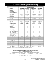
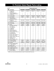
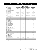
Premium Select Repair Parts Listing Ref. Description Hanger Pack, containing: 1 Bracket, Hanger (1) 2 Hanger Ball Assembly (1) 3 Downrod (1) 6 Cover, Ceiling 7 Hub, Rubber 8 Blade Assembly (Full set for optional blade accessories. Model No.: CF4801 and CF4501 Owner's Manual CF4801ORB00 761655-32 - - - 761620-ORB 760601 * 764164-ORB 761991-ORB 761621-ORB 762508 764196-1 762242 760671-25 761450-2 - - - 761790 761993-2 BP7447-1 Premium Select Series CF4801SW00 ...
Premium Select Repair Parts Listing Ref. Description Hanger Pack, containing: 1 Bracket, Hanger (1) 2 Hanger Ball Assembly (1) 3 Downrod (1) 6 Cover, Ceiling 7 Hub, Rubber 8 Blade Assembly (Full set for optional blade accessories. Model No.: CF4801 and CF4501 Owner's Manual CF4801ORB00 761655-32 - - - 761620-ORB 760601 * 764164-ORB 761991-ORB 761621-ORB 762508 764196-1 762242 760671-25 761450-2 - - - 761790 761993-2 BP7447-1 Premium Select Series CF4801SW00 ...
Owner Manual
Page 16
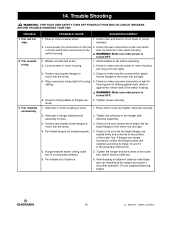
... sure wire connectors in light kit rattling. switch housing. ! Check to fan and switch or loose switch wire connections in the wire connections in hanger ball/downrod assembly is loose. 1. Raise motor cover and tighten setscrew securely. 2. Setscrew in the switch housing. Screws securing fan blade flanges to the fan, 2. Fan blade flanges not seated properly. 5. Interchanging an adjacent (side-by-side) blade pair can redistribute the weight and result in motor housing. 2. Fuse or circuit breaker blown. 1. Loose power line connections to motor...
... sure wire connectors in light kit rattling. switch housing. ! Check to fan and switch or loose switch wire connections in the wire connections in hanger ball/downrod assembly is loose. 1. Raise motor cover and tighten setscrew securely. 2. Setscrew in the switch housing. Screws securing fan blade flanges to the fan, 2. Fan blade flanges not seated properly. 5. Interchanging an adjacent (side-by-side) blade pair can redistribute the weight and result in motor housing. 2. Fuse or circuit breaker blown. 1. Loose power line connections to motor...
Owner Manual
Page 17
Model No.: CF4801 and CF4501 Notes emersonfans.com Please contact 1-800-654-3545 for further assistance 17 U.L.
Model No.: CF4801 and CF4501 Notes emersonfans.com Please contact 1-800-654-3545 for further assistance 17 U.L.
Owner Manual
Page 18
Model No.: CF4801 and CF4501 Notes 18 U.L.
Model No.: CF4801 and CF4501 Notes 18 U.L.
Owner Manual
Page 19
... ship the repaired or the replacement Emerson Ceiling Fan to you must be sent to the mailing address you provide to you as part of this limited warranty. The return label will repair or replace the defective motor, component or other components and accessories of the Emerson Ceiling Fan against all model numbers shown on behalf of Air Comfort Products or Emerson Electric Co. What We Will Do To Correct Problems...
... ship the repaired or the replacement Emerson Ceiling Fan to you must be sent to the mailing address you provide to you as part of this limited warranty. The return label will repair or replace the defective motor, component or other components and accessories of the Emerson Ceiling Fan against all model numbers shown on behalf of Air Comfort Products or Emerson Electric Co. What We Will Do To Correct Problems...

Owner Manual
Page 20
Part No. Model No.: CF4801 and CF4501 Louis, MO 63136 Questions, problems, missing parts: Before returning to the store call Emerson Electric Customer Service 8 a.m. - 6 p.m., Eastern, Monday-Friday 1-800-654-3545 www.emersonfans.com Retain this manual for future use. F40BP74470001 Revision: 131113 Printed in China 11/13 Form No. BP7447-1 U.L. Air Comfort Products DIVISION OF EMERSON ELECTRIC CO. 8100 W. Florissant • St.
Part No. Model No.: CF4801 and CF4501 Louis, MO 63136 Questions, problems, missing parts: Before returning to the store call Emerson Electric Customer Service 8 a.m. - 6 p.m., Eastern, Monday-Friday 1-800-654-3545 www.emersonfans.com Retain this manual for future use. F40BP74470001 Revision: 131113 Printed in China 11/13 Form No. BP7447-1 U.L. Air Comfort Products DIVISION OF EMERSON ELECTRIC CO. 8100 W. Florissant • St.


