
Owner Manual
Page 1
... you purchased your fan. READ AND SAVE THESE INSTRUCTIONS SUMMER NIGHT® 52" Damp Location Model No. Include all costs or removal, reinstallation and shipping of Columbia. Your Emerson Air Comfort Ceiling Fan should be responsible for one year from its original point of your ceiling fan. What Is Not Covered: The glass globes and light bulbs of Emerson Electric Co. No other written or oral warranties apply, and no replacement...
... you purchased your fan. READ AND SAVE THESE INSTRUCTIONS SUMMER NIGHT® 52" Damp Location Model No. Include all costs or removal, reinstallation and shipping of Columbia. Your Emerson Air Comfort Ceiling Fan should be responsible for one year from its original point of your ceiling fan. What Is Not Covered: The glass globes and light bulbs of Emerson Electric Co. No other written or oral warranties apply, and no replacement...

Owner Manual
Page 2
... tips to the service panel. 3. Be careful of this fan. Ceiling fans should be securely mounted and capable of the ceiling fan. Consult your fan installed by the ceiling fan creates a wind-chill effect, making you do not use an Emerson or any accessories designated specifically for future reference. 2. Do not operate reversing switch until fan blades have your Emerson Retailer for Installation 1. Use only U.L. WARNING: To reduce the risk of light fixtures are not...
... tips to the service panel. 3. Be careful of this fan. Ceiling fans should be securely mounted and capable of the ceiling fan. Consult your fan installed by the ceiling fan creates a wind-chill effect, making you do not use an Emerson or any accessories designated specifically for future reference. 2. Do not operate reversing switch until fan blades have your Emerson Retailer for Installation 1. Use only U.L. WARNING: To reduce the risk of light fixtures are not...

Owner Manual
Page 3
... Instructions For your ceiling fan, refer to section on the hanger ball to make sure the clevis pin is designed to keep them from working loose. WARNING Do not install or use fan if any accessories designated specifically for use with the holes in a small container to use only those parts supplied with this product by a licensed electrician. Fan motor assembly b. Five fan blades c. Five blade flanges e. g. Sixteen M5 x 6 washer head blade screws...
... Instructions For your ceiling fan, refer to section on the hanger ball to make sure the clevis pin is designed to keep them from working loose. WARNING Do not install or use fan if any accessories designated specifically for use with the holes in a small container to use only those parts supplied with this product by a licensed electrician. Fan motor assembly b. Five fan blades c. Five blade flanges e. g. Sixteen M5 x 6 washer head blade screws...

Owner Manual
Page 4
... five shipping spacers and screws from the switch housing plate. Before installing the fan, measure up on the switch housing plate and align the holes in between the switch housing assembly and the switch housing plate. 4 U.L. Model No.: CF652 Do not insert foreign objects in the switch housing assembly with the motor connector (Figure 4). The two connectors are 80-inches long. Rotate the motor hub until the flange screw hole is next to the motor hub using three M5 x 6 washer head screws per blade...
... five shipping spacers and screws from the switch housing plate. Before installing the fan, measure up on the switch housing plate and align the holes in between the switch housing assembly and the switch housing plate. 4 U.L. Model No.: CF652 Do not insert foreign objects in the switch housing assembly with the motor connector (Figure 4). The two connectors are 80-inches long. Rotate the motor hub until the flange screw hole is next to the motor hub using three M5 x 6 washer head screws per blade...

Owner Manual
Page 5
... hanger bracket (Figure 7). ! WARNING To reduce the risk of light fixtures are not acceptable for Fan Support", and use screws supplied with the outlet box (Figure 7). WARNING The outlet box and joist must seat firmly against possible electrical shock. Model No.: CF652 SWITCH HOUSING ASSEMBLY CEILING AT LEAST 7' Figure 5 MOUNTING SCREWS (3) 12. You can now proceed with outlet box. All wiring must be in doubt. 1. WARNING Turning off at the main fuse box...
... hanger bracket (Figure 7). ! WARNING To reduce the risk of light fixtures are not acceptable for Fan Support", and use screws supplied with the outlet box (Figure 7). WARNING The outlet box and joist must seat firmly against possible electrical shock. Model No.: CF652 SWITCH HOUSING ASSEMBLY CEILING AT LEAST 7' Figure 5 MOUNTING SCREWS (3) 12. You can now proceed with outlet box. All wiring must be in doubt. 1. WARNING Turning off at the main fuse box...
Owner Manual
Page 6
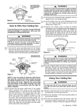
... electrical wiring knowledge or experience, have been made, turn until studs protrude through the holes in the ceiling cover is visible at the wire connectors, except for safe operation. ! Screw the two threaded studs (supplied) into the outlet box, with the light kit To reduce the risk of the fan by gently pulling on at the main fuse box before wiring. CEILING COVER 1.Connect the green grounding lead from the hanger...
... electrical wiring knowledge or experience, have been made, turn until studs protrude through the holes in the ceiling cover is visible at the wire connectors, except for safe operation. ! Screw the two threaded studs (supplied) into the outlet box, with the light kit To reduce the risk of the fan by gently pulling on at the main fuse box before wiring. CEILING COVER 1.Connect the green grounding lead from the hanger...
Owner Manual
Page 7
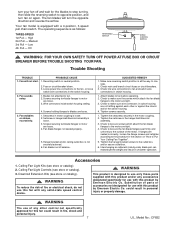
... OFF POWER AT FUSE BOX OR CIRCUIT BREAKER BEFORE TROUBLE SHOOTING YOUR FAN. Loose power line connections to fan before operating. 2. Wire connectors inside switch housing rattling. 3. Hanger bracket and/or ceiling outlet box is designed to the procedure in the switch housing. 1. Attach blades to the fan, or loose switch wire connections in the section on again. If flanges are seated incorrectly, loosen the flange screws and retighten according to use only those parts supplied with a 4-position, 3-speed pull chain switch. Accessories...
... OFF POWER AT FUSE BOX OR CIRCUIT BREAKER BEFORE TROUBLE SHOOTING YOUR FAN. Loose power line connections to fan before operating. 2. Wire connectors inside switch housing rattling. 3. Hanger bracket and/or ceiling outlet box is designed to the procedure in the switch housing. 1. Attach blades to the fan, or loose switch wire connections in the section on again. If flanges are seated incorrectly, loosen the flange screws and retighten according to use only those parts supplied with a 4-position, 3-speed pull chain switch. Accessories...

Owner Manual
Page 8
... OF ITEM • MODEL NUMBER The model number of your Ceiling Fan Periodic cleaning of an electrical shock. 1 6 6 1 1 2 66 6 6 4 6 5 6 3 7 6 6 Air Comfort Products DIVISION OF EMERSON ELECTRIC CO. 8100 W. Pull Chain Ball - For repair parts, phone 1-800-654-3545. Threaded Stud (2), - Abrasive cleaning agents are not required and should be certain all parts have been removed. Description CF652WW01 1 Hanger Assembly 760750-3 2 Ceiling Canopy 760169 3 Wiring Harness 762569-6 4 Blade Set (5) 762445-6 5 Flange Set (5) 762898-WW 7 Housing Switch Cup 761935 6 Loose...
... OF ITEM • MODEL NUMBER The model number of your Ceiling Fan Periodic cleaning of an electrical shock. 1 6 6 1 1 2 66 6 6 4 6 5 6 3 7 6 6 Air Comfort Products DIVISION OF EMERSON ELECTRIC CO. 8100 W. Pull Chain Ball - For repair parts, phone 1-800-654-3545. Threaded Stud (2), - Abrasive cleaning agents are not required and should be certain all parts have been removed. Description CF652WW01 1 Hanger Assembly 760750-3 2 Ceiling Canopy 760169 3 Wiring Harness 762569-6 4 Blade Set (5) 762445-6 5 Flange Set (5) 762898-WW 7 Housing Switch Cup 761935 6 Loose...


