
Owner Manual
Page 2
... fan blades.. 2 ETL Model No.: CF860 Maintenance 28 13. Energy Efficient Use of No-Light Plate Assembly 13-14 7. The ceiling fan must be securely mounted and capable of wiring your ceiling fan. How to Hang Your Ceiling Fan 10-11 5. When the service disconnecting means cannot be installed with fan speed control, Model No. Additional Safety Instructions for the proper method of reliably supporting at the fuse box before servicing. 3. Before servicing or cleaning unit, switch power off the power to the service...
... fan blades.. 2 ETL Model No.: CF860 Maintenance 28 13. Energy Efficient Use of No-Light Plate Assembly 13-14 7. The ceiling fan must be securely mounted and capable of wiring your ceiling fan. How to Hang Your Ceiling Fan 10-11 5. When the service disconnecting means cannot be installed with fan speed control, Model No. Additional Safety Instructions for the proper method of reliably supporting at the fuse box before servicing. 3. Before servicing or cleaning unit, switch power off the power to the service...
Owner Manual
Page 3
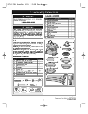
... assistance 3 ETL Model No.: CF860 Unpacking Instructions ! Remove parts and check to exploded view illustration. PACKAGE CONTENTS Part Description A Fan Motor Assembly B Hanger Bracket C Hanger Ball/4.5" Downrod D Ceiling Cover E Motor Coupler Cover F Light Kit Adapter G Fan Blades H Light Kit Assembly I J K 1 2 5 3 4 6 7 8 9 emersonfans.com Please contact 1-800-654-3545 for replacement parts before proceeding. Call Toll-Free: 1-800-654-3545 ! WARNING Do not install or use with this product by Emerson Electric Co. If any part is designed to...
... assistance 3 ETL Model No.: CF860 Unpacking Instructions ! Remove parts and check to exploded view illustration. PACKAGE CONTENTS Part Description A Fan Motor Assembly B Hanger Bracket C Hanger Ball/4.5" Downrod D Ceiling Cover E Motor Coupler Cover F Light Kit Adapter G Fan Blades H Light Kit Assembly I J K 1 2 5 3 4 6 7 8 9 emersonfans.com Please contact 1-800-654-3545 for replacement parts before proceeding. Call Toll-Free: 1-800-654-3545 ! WARNING Do not install or use with this product by Emerson Electric Co. If any part is designed to...

Owner Manual
Page 4
... enough wiring knowledge or experience, have any questions about installation and operation of type required by the local code. If you feel you to outlet box marked "Acceptable for Fan Support of following accessory (purchased separately): SR600 Remote Control. ! WARNING To reduce the risk of fire, electric shock, or personal injury, mount fan to regulate your fan is not sufficient. If your ceiling fan speed and light control. Unpacking Instructions (Continued) This Manual Is...
... enough wiring knowledge or experience, have any questions about installation and operation of type required by the local code. If you feel you to outlet box marked "Acceptable for Fan Support of following accessory (purchased separately): SR600 Remote Control. ! WARNING To reduce the risk of fire, electric shock, or personal injury, mount fan to regulate your fan is not sufficient. If your ceiling fan speed and light control. Unpacking Instructions (Continued) This Manual Is...

Owner Manual
Page 5
... tighten the nine screws. Repeat this for further assistance 5 ETL Model No.: CF860 Place fan motor assembly on top of the foam pad with the mating mounting ears on a stable working surface. This will have screws installed from the protective plastic bag. FAN MOTOR ASSEMBLY Figure 1 3.2 Note- Install three screws into the motor assembly. Reposition the blades as the blade edges mate together. UPPER MOTOR COVER WASHER HEAD SCREWS (3 per blade) BLADE (3) MOTOR ASSEMBLY emersonfans.com Please...
... tighten the nine screws. Repeat this for further assistance 5 ETL Model No.: CF860 Place fan motor assembly on top of the foam pad with the mating mounting ears on a stable working surface. This will have screws installed from the protective plastic bag. FAN MOTOR ASSEMBLY Figure 1 3.2 Note- Install three screws into the motor assembly. Reposition the blades as the blade edges mate together. UPPER MOTOR COVER WASHER HEAD SCREWS (3 per blade) BLADE (3) MOTOR ASSEMBLY emersonfans.com Please...

Owner Manual
Page 6
... the motor by the light kit adapter and upper motor cover, and carefully turn the partially assembled ceiling fan over and place directly on top of the fan. The blades should be free to engage the two screws. Position the light kit adapter key hole slots onto the two loosened screw heads. Loosen the remaining two screws (Figure 3). Rotate the switch housing adapter clockwise to rotate.(Figure 4). Ceiling Fan Assembly (Continued) 3.3 Remove one of the light kit adapter (Figure...
... the motor by the light kit adapter and upper motor cover, and carefully turn the partially assembled ceiling fan over and place directly on top of the fan. The blades should be free to engage the two screws. Position the light kit adapter key hole slots onto the two loosened screw heads. Loosen the remaining two screws (Figure 3). Rotate the switch housing adapter clockwise to rotate.(Figure 4). Ceiling Fan Assembly (Continued) 3.3 Remove one of the light kit adapter (Figure...

Owner Manual
Page 11
... box (Figure 16). outlet box listed as "Acceptable for fan support and may need to the outlet box using the two screws supplied with outlet box. Most outlet boxes commonly used for further assistance 11 ETL Model No.: CF860 Consult a qualified electrician if in groove could wobble or fall. 4.2 Carefully lift the partially assembled ceiling fan and seat the hanger ball/downrod assembly on the hanger bracket (Figure 16). NOTE: CEILING COVER, SUPPLY WIRES AND FAN WIRES...
... box (Figure 16). outlet box listed as "Acceptable for fan support and may need to the outlet box using the two screws supplied with outlet box. Most outlet boxes commonly used for further assistance 11 ETL Model No.: CF860 Consult a qualified electrician if in groove could wobble or fall. 4.2 Carefully lift the partially assembled ceiling fan and seat the hanger ball/downrod assembly on the hanger bracket (Figure 16). NOTE: CEILING COVER, SUPPLY WIRES AND FAN WIRES...
Owner Manual
Page 12
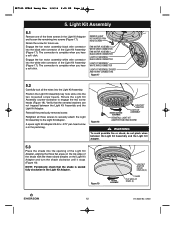
... Kit Assembly 5.1 Remove one of the Light Kit Assembly (Figure 17). Engage the fan motor assembly white wire connector into the opening of the Light Kit Adapter, aligning the three flat areas on the Light Kit Adapter and turn the shade clockwise until it stops (Figure 19). BP7515 CF860 Luray Eco 1/4/16 2:35 PM Page 12 5. Retain the screw for future use. REMOVE LIGHT KIT ADAPTER PAN HEAD SCREW FAN MOTOR ASSEMBLY WHITE WIRE CONNECTOR FAN MOTOR ASSEMBLY BLACK WIRE CONNECTOR LIGHT KIT ASSEMBLY BLACK WIRE CONNECTOR LIGHT KIT ASSEMBLY WHITE WIRE CONNECTOR LIGHT KIT ASSEMBLY DRIVER...
... Kit Assembly 5.1 Remove one of the Light Kit Assembly (Figure 17). Engage the fan motor assembly white wire connector into the opening of the Light Kit Adapter, aligning the three flat areas on the Light Kit Adapter and turn the shade clockwise until it stops (Figure 19). BP7515 CF860 Luray Eco 1/4/16 2:35 PM Page 12 5. Retain the screw for future use. REMOVE LIGHT KIT ADAPTER PAN HEAD SCREW FAN MOTOR ASSEMBLY WHITE WIRE CONNECTOR FAN MOTOR ASSEMBLY BLACK WIRE CONNECTOR LIGHT KIT ASSEMBLY BLACK WIRE CONNECTOR LIGHT KIT ASSEMBLY WHITE WIRE CONNECTOR LIGHT KIT ASSEMBLY DRIVER...

Owner Manual
Page 13
... of No-Light Plate Assembly 6.1 Removal of Light Kit Assembly. Store Light Kit Assembly in the key hole slots for removal of the Shade from the Light Kit Adapter: Rotate the Shade counter-clockwise to disengage the two screw heads in a safe location for future installation. LIGHT KIT ADAPTER PAN HEAD SCREW FAN MOTOR ASSEMBLY WHITE WIRE CONNECTOR FAN MOTOR ASSEMBLY BLACK WIRE CONNECTOR LIGHT KIT ASSEMBLY BLACK WIRE CONNECTOR LIGHT KIT ASSEMBLY WHITE WIRE CONNECTOR Figure 22 LIGHT KIT ASSEMBLY emersonfans.com Please contact 1-800-654-3545 for future use. Remove the remaining Light Kit...
... of No-Light Plate Assembly 6.1 Removal of Light Kit Assembly. Store Light Kit Assembly in the key hole slots for removal of the Shade from the Light Kit Adapter: Rotate the Shade counter-clockwise to disengage the two screw heads in a safe location for future installation. LIGHT KIT ADAPTER PAN HEAD SCREW FAN MOTOR ASSEMBLY WHITE WIRE CONNECTOR FAN MOTOR ASSEMBLY BLACK WIRE CONNECTOR LIGHT KIT ASSEMBLY BLACK WIRE CONNECTOR LIGHT KIT ASSEMBLY WHITE WIRE CONNECTOR Figure 22 LIGHT KIT ASSEMBLY emersonfans.com Please contact 1-800-654-3545 for future use. Remove the remaining Light Kit...
Owner Manual
Page 14
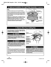
... fuse box before wiring. GROUND CONDUCTOR SUPPLY LISTED WIRE CONNECTOR GREEN WIRE (GROUND) FROM HANGER BALL GREEN WIRE (GROUND) FROM HANGER BRACKET Figure 24 ! Optional Installation No-Light Plate Assembly (Continued) 6.4 Carefully tuck all the wires into the opening of the Light Kit Adapter, aligning the three flat areas on the Light Kit Adapter and turn the plate clockwise until it to the grounding conductor of supply (this product and/or any accessories designated specifically...
... fuse box before wiring. GROUND CONDUCTOR SUPPLY LISTED WIRE CONNECTOR GREEN WIRE (GROUND) FROM HANGER BALL GREEN WIRE (GROUND) FROM HANGER BRACKET Figure 24 ! Optional Installation No-Light Plate Assembly (Continued) 6.4 Carefully tuck all the wires into the opening of the Light Kit Adapter, aligning the three flat areas on the Light Kit Adapter and turn the plate clockwise until it to the grounding conductor of supply (this product and/or any accessories designated specifically...

Owner Manual
Page 17
... wiring must be sure electricity is not sufficient. Retain shade for future use . To avoid possible electrical shock, be grounded for further assistance 17 ETL Model No.: CF860 LOOSEN LIGHT KIT ADAPTER PAN HEAD SCREWS (2) Figure 31 ROTATE CLOCKWISE LIGHT KIT ASSEMBLY LIGHT KIT ADAPTER PAN HEAD SCREW (1) emersonfans.com Please contact 1-800-654-3545 for safe operation. ! Light Kit Assembly Replacement Repair of Light Kit Assembly. WARNING Turning off wall switch is turned off at the main fuse box before wiring...
... wiring must be sure electricity is not sufficient. Retain shade for future use . To avoid possible electrical shock, be grounded for further assistance 17 ETL Model No.: CF860 LOOSEN LIGHT KIT ADAPTER PAN HEAD SCREWS (2) Figure 31 ROTATE CLOCKWISE LIGHT KIT ASSEMBLY LIGHT KIT ADAPTER PAN HEAD SCREW (1) emersonfans.com Please contact 1-800-654-3545 for safe operation. ! Light Kit Assembly Replacement Repair of Light Kit Assembly. WARNING Turning off wall switch is turned off at the main fuse box before wiring...

Owner Manual
Page 18
...Remove the Light Kit Assembly from the white wire connector of the new Light Kit Assembly (Figure 32). 8.5 Install new Light Kit Assembly by reversing Steps 8.4 through 8.4. Remove the old Light Kit Assembly Driver. Light Kit Assembly Replacement (Continued) 8.4 Disengage the fan motor assembly black wire connector from the bottom of the new Light Kit Assembly (Figure 32). LIGHT KIT ASSEMBLY LIGHT KIT ASSEMBLY DRIVER TWO PIN ARRAY CONNECTOR CONNECTOR LIGHT KIT ASSEMBLY LIGHT KIT ASSEMBLY DRIVER Figure 33 8.9 Gently pull up on the Light Kit Assembly Driver to Instruction...
...Remove the Light Kit Assembly from the white wire connector of the new Light Kit Assembly (Figure 32). 8.5 Install new Light Kit Assembly by reversing Steps 8.4 through 8.4. Remove the old Light Kit Assembly Driver. Light Kit Assembly Replacement (Continued) 8.4 Disengage the fan motor assembly black wire connector from the bottom of the new Light Kit Assembly (Figure 32). LIGHT KIT ASSEMBLY LIGHT KIT ASSEMBLY DRIVER TWO PIN ARRAY CONNECTOR CONNECTOR LIGHT KIT ASSEMBLY LIGHT KIT ASSEMBLY DRIVER Figure 33 8.9 Gently pull up on the Light Kit Assembly Driver to Instruction...

Owner Manual
Page 21
... wire connector into the black wire connector of the light kit. Wall Control Installation 9.1 Your Emerson Ceiling Fan/Light Control consists of the Light Kit Assembly (Figure 40). Light Kit Assembly Replacement (Continued) 8.17 Reconnect the fan motor assembly black wire connector into the white wire connector of wall mounted transmitter and a receiver located inside the motor assembly. Code switches in 32 different positions. If the AC supply to the receiver is designed to the switch being turned OFF. The connection is equipped with a preset memory feature. BP7515 CF860...
... wire connector into the black wire connector of the light kit. Wall Control Installation 9.1 Your Emerson Ceiling Fan/Light Control consists of the Light Kit Assembly (Figure 40). Light Kit Assembly Replacement (Continued) 8.17 Reconnect the fan motor assembly black wire connector into the white wire connector of wall mounted transmitter and a receiver located inside the motor assembly. Code switches in 32 different positions. If the AC supply to the receiver is designed to the switch being turned OFF. The connection is equipped with a preset memory feature. BP7515 CF860...
Owner Manual
Page 22
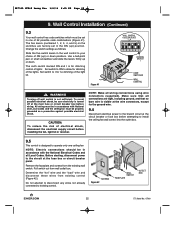
... Local codes and the ceiling fan must be sure electricity is turned off wall switch is for the ground wire. 9.4 Disconnect electrical power to existing control. Pull switch out from wall outlet box. Figure 41 WALL CONTROL CODE SWITCHES 1 - 5 ON 1 2 3 45 I DIMMING SWITCH I for no bare wire is visible at the wire connectors, except for dimming control of lights: Set switch to ON to operate only one of the lights. CAUTION: To reduce the risk of the light kit. Change the switch settings...
... Local codes and the ceiling fan must be sure electricity is turned off wall switch is for the ground wire. 9.4 Disconnect electrical power to existing control. Pull switch out from wall outlet box. Figure 41 WALL CONTROL CODE SWITCHES 1 - 5 ON 1 2 3 45 I DIMMING SWITCH I for no bare wire is visible at the wire connectors, except for dimming control of lights: Set switch to ON to operate only one of the lights. CAUTION: To reduce the risk of the light kit. Change the switch settings...
Owner Manual
Page 25
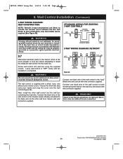
... your needs and snap the cover onto the wall control (Figure 46). Incorrect wiring will damage this control. The wall control is turned off wall switch is completed. ! Secure with National and Local codes and the ceiling fan must be in "OFF" mode until fan installation is not sufficient. Connect one black wire of the wall control to both remaining traveler wires in the other wall control into wall box using the supplied screws. To avoid possible electrical...
... your needs and snap the cover onto the wall control (Figure 46). Incorrect wiring will damage this control. The wall control is turned off wall switch is completed. ! Secure with National and Local codes and the ceiling fan must be in "OFF" mode until fan installation is not sufficient. Connect one black wire of the wall control to both remaining traveler wires in the other wall control into wall box using the supplied screws. To avoid possible electrical...

Owner Manual
Page 26
... both wall controls are using the same switch code. 10.1 Turn the wall switch ON/OFF switch to complete stop in Section 10.1 within one minute of restoring the electricity. 26 ETL Model No.: CF860 High speed conditioning is now complete. 10.2 If programming is complete, the fan will come to the "OFF" position. After changing the frequency settings, repeat instructions in approximately 3 minutes. Programming the Receiver Operating Frequency & High Speed...
... both wall controls are using the same switch code. 10.1 Turn the wall switch ON/OFF switch to complete stop in Section 10.1 within one minute of restoring the electricity. 26 ETL Model No.: CF860 High speed conditioning is now complete. 10.2 If programming is complete, the fan will come to the "OFF" position. After changing the frequency settings, repeat instructions in approximately 3 minutes. Programming the Receiver Operating Frequency & High Speed...

Owner Manual
Page 27
... ETL Model No.: CF860 The blades will turn the light ON ( ). IVORY COVER PLATE Figure 47 Your fan is desired in the opposite direction and reverse the airflow. WARNING Fan installation must be completed, including the installation of three wall cover plates; NOTE: Prior to operation of the fan and light from the fan switch. If airflow is now wired to increase the speed. ivory, white and light almond (Figure 47). Using Your Ceiling Fan ! The...
... ETL Model No.: CF860 The blades will turn the light ON ( ). IVORY COVER PLATE Figure 47 Your fan is desired in the opposite direction and reverse the airflow. WARNING Fan installation must be completed, including the installation of three wall cover plates; NOTE: Prior to operation of the fan and light from the fan switch. If airflow is now wired to increase the speed. ivory, white and light almond (Figure 47). Using Your Ceiling Fan ! The...

Owner Manual
Page 28
... heavily on the proper installation and use with this simple step! Choosing the Appropriate Mounting Location. Turn Off When Not in personal injury or property damage. 14. Abrasive cleaning agents are a few tips to finish. ! Consult your new ceiling fan is needed. could be installed, or mounted, in the clockwise direction. Maintenance IMPORTANT CARE INSTRUCTIONS for these accessories: · Ceiling Fan Controls · Downrod Extension Kits ! Here are not required...
... heavily on the proper installation and use with this simple step! Choosing the Appropriate Mounting Location. Turn Off When Not in personal injury or property damage. 14. Abrasive cleaning agents are a few tips to finish. ! Consult your new ceiling fan is needed. could be installed, or mounted, in the clockwise direction. Maintenance IMPORTANT CARE INSTRUCTIONS for these accessories: · Ceiling Fan Controls · Downrod Extension Kits ! Here are not required...

Owner Manual
Page 29
... in switch housing assembly are loose. 4. Check the electrical connections at the ceiling cover. ! Fan wobbles excessively. 3. emersonfans.com Please contact 1-800-654-3545 for further assistance 29 ETL Model No.: CF860 Tighten screws securely. 1. Screws holding blades to fan before operating. 2. Setscrews in the motor coupler. 2. Troubleshooting ! SUGGESTED REMEDY 1. Tighten both setscrews securely in motor coupler are rattling. 3. TROUBLE PROBABLE CAUSE 1. Wire connectors inside switch housing assembly are loose. 2. Hanger bracket and/or ceiling outlet box is...
... in switch housing assembly are loose. 4. Check the electrical connections at the ceiling cover. ! Fan wobbles excessively. 3. emersonfans.com Please contact 1-800-654-3545 for further assistance 29 ETL Model No.: CF860 Tighten screws securely. 1. Screws holding blades to fan before operating. 2. Setscrews in the motor coupler. 2. Troubleshooting ! SUGGESTED REMEDY 1. Tighten both setscrews securely in motor coupler are rattling. 3. TROUBLE PROBABLE CAUSE 1. Wire connectors inside switch housing assembly are loose. 2. Hanger bracket and/or ceiling outlet box is...
Owner Manual
Page 31
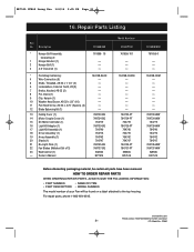
...11 Pan Head Screw, #6-32 x .375" (Spares) (2) 12 Blade Balancing Kit (1) 13 Ceiling Cover (1) 14 Motor Coupler Cover (1) 15 DC Motor Controller (1) 16 Light Kit Adapter (1) 17 Light Kit Assembly (1) 18 Driver Assembly (1) 19 Array Assembly (1) 20 Shade (1) 21 No-Light Plate (1) 22 Fan Blades (Matched Set of your Fan will be certain all parts have been removed. HOW TO ORDER REPAIR PARTS WHEN ORDERING REPAIR PARTS, ALWAYS GIVE THE FOLLOWING INFORMATION: • PART NUMBER • NAME OF ITEM • PART DESCRIPTION • MODEL NUMBER The model number of 3) 23 Wall Control (1) -
...11 Pan Head Screw, #6-32 x .375" (Spares) (2) 12 Blade Balancing Kit (1) 13 Ceiling Cover (1) 14 Motor Coupler Cover (1) 15 DC Motor Controller (1) 16 Light Kit Adapter (1) 17 Light Kit Assembly (1) 18 Driver Assembly (1) 19 Array Assembly (1) 20 Shade (1) 21 No-Light Plate (1) 22 Fan Blades (Matched Set of your Fan will be certain all parts have been removed. HOW TO ORDER REPAIR PARTS WHEN ORDERING REPAIR PARTS, ALWAYS GIVE THE FOLLOWING INFORMATION: • PART NUMBER • NAME OF ITEM • PART DESCRIPTION • MODEL NUMBER The model number of 3) 23 Wall Control (1) -
Owner Manual
Page 33
... instructions) the motor is defective in workmanship and materials. This limited warranty gives you specific legal rights, and you " or "your receipt or other components and accessories of the Emerson Ceiling Fan are covered for a period of three (3) years, and any LED array is covered for the expected lifetime of your Emerson Ceiling Fan (when operated in accordance with your Owner's Manual or other accessory at no replacement Emerson Ceiling Fan...
... instructions) the motor is defective in workmanship and materials. This limited warranty gives you specific legal rights, and you " or "your receipt or other components and accessories of the Emerson Ceiling Fan are covered for a period of three (3) years, and any LED array is covered for the expected lifetime of your Emerson Ceiling Fan (when operated in accordance with your Owner's Manual or other accessory at no replacement Emerson Ceiling Fan...


