

Owner Manual
Page 1
... Form No. BP7515 ETL Model No.: CF860 página 34 • Français - BP7515 CF860 Luray Eco 1/4/16 2:35 PM Page 1 READ AND SAVE THESE INSTRUCTIONS CONTEMPORARY LURAY ECO™ 60" Damp Location Ceiling Fan Owner's Manual Model Numbers CF860BQ00 - Questions, problems, missing parts: Before returning to the store call Emerson Electric Customer Service - 8 a.m. - 6 p.m., Eastern, Monday...
... Form No. BP7515 ETL Model No.: CF860 página 34 • Français - BP7515 CF860 Luray Eco 1/4/16 2:35 PM Page 1 READ AND SAVE THESE INSTRUCTIONS CONTEMPORARY LURAY ECO™ 60" Damp Location Ceiling Fan Owner's Manual Model Numbers CF860BQ00 - Questions, problems, missing parts: Before returning to the store call Emerson Electric Customer Service - 8 a.m. - 6 p.m., Eastern, Monday...
Owner Manual
Page 2
... wiring your ceiling fan. Follow the recommended instructions for fan support and may need to prevent accidental contact with the outlet box. BP7515 CF860 Luray Eco 1/4/16 2:35 PM Page 2 Table of the fan and blades when cleaning, painting, or working near the fan. To avoid possible...sure electricity is designed to fan blade clearance for support of fire or electrical shock, this unit only in a manner intended by Emerson could result in accordance with an isolating wall control/switch. Light Kit Assembly 12 6. Additional Safety Instructions for use the mounting ...
... wiring your ceiling fan. Follow the recommended instructions for fan support and may need to prevent accidental contact with the outlet box. BP7515 CF860 Luray Eco 1/4/16 2:35 PM Page 2 Table of the fan and blades when cleaning, painting, or working near the fan. To avoid possible...sure electricity is designed to fan blade clearance for support of fire or electrical shock, this unit only in a manner intended by Emerson could result in accordance with an isolating wall control/switch. Light Kit Assembly 12 6. Additional Safety Instructions for use the mounting ...
Owner Manual
Page 3
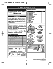
... K 1 2 5 3 4 6 7 8 9 emersonfans.com Please contact 1-800-654-3545 for use with this product by Emerson Electric Co. NOTE: Place the parts from the loose parts bags in personal injury or property damage. Unpacking Instructions ! Call Toll...I Shade J No-Light Plate K Wall Control 1.1 Open carton containing fan. Substitution of parts or accessories not designated for replacement parts before proceeding. BP7515 CF860 Luray Eco 1/4/16 2:35 PM Page 3 1. WARNING Do not install or use fan if any parts are uncertain of styrofoam unit. If any part is designed ...
... K 1 2 5 3 4 6 7 8 9 emersonfans.com Please contact 1-800-654-3545 for use with this product by Emerson Electric Co. NOTE: Place the parts from the loose parts bags in personal injury or property damage. Unpacking Instructions ! Call Toll...I Shade J No-Light Plate K Wall Control 1.1 Open carton containing fan. Substitution of parts or accessories not designated for replacement parts before proceeding. BP7515 CF860 Luray Eco 1/4/16 2:35 PM Page 3 1. WARNING Do not install or use fan if any parts are uncertain of styrofoam unit. If any part is designed ...

Owner Manual
Page 4
...IN DAMP LOCATIONS. Tools Needed for Fan Support of wiring your fan installed by a licensed electrician. 2. Wire Size A.W.G. 14 12 Your Emerson Ceiling Fan comes supplied with outlet box. WARNING Before assembling your ceiling fan, refer to Make it as Easy as a precaution against .... If your ceiling fan speed and light control. Please call Emerson technical support at this ceiling fan. ! If you feel you to regulate your fan is not sufficient. Any electrical work not described in doubt. BP7515 CF860 Luray Eco 1/4/16 2:35 PM Page 4 1. The minimum wire would ...
...IN DAMP LOCATIONS. Tools Needed for Fan Support of wiring your fan installed by a licensed electrician. 2. Wire Size A.W.G. 14 12 Your Emerson Ceiling Fan comes supplied with outlet box. WARNING Before assembling your ceiling fan, refer to Make it as Easy as a precaution against .... If your ceiling fan speed and light control. Please call Emerson technical support at this ceiling fan. ! If you feel you to regulate your fan is not sufficient. Any electrical work not described in doubt. BP7515 CF860 Luray Eco 1/4/16 2:35 PM Page 4 1. The minimum wire would ...

Owner Manual
Page 5
...COVER WASHER HEAD SCREWS (3 per blade) BLADE (3) MOTOR ASSEMBLY emersonfans.com Please contact 1-800-654-3545 for further assistance 5 ETL Model No.: CF860 BLADE LARGE MOUNTING FLANGE BLADE MOUNTING TAB Figure 2 ! Ceiling Fan Assembly 3.1 Flip the upper foam pad over and place on top of the... when installing, balancing the blades or cleaning the fan. After all three blades are installed and aligned, completely tighten the nine screws. BP7515 CF860 Luray Eco 1/4/16 2:35 PM Page 5 3. Place fan motor assembly on a stable working surface. You may hear a popping noise as needed to...
...COVER WASHER HEAD SCREWS (3 per blade) BLADE (3) MOTOR ASSEMBLY emersonfans.com Please contact 1-800-654-3545 for further assistance 5 ETL Model No.: CF860 BLADE LARGE MOUNTING FLANGE BLADE MOUNTING TAB Figure 2 ! Ceiling Fan Assembly 3.1 Flip the upper foam pad over and place on top of the... when installing, balancing the blades or cleaning the fan. After all three blades are installed and aligned, completely tighten the nine screws. BP7515 CF860 Luray Eco 1/4/16 2:35 PM Page 5 3. Place fan motor assembly on a stable working surface. You may hear a popping noise as needed to...

Owner Manual
Page 6
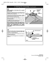
... loosened screw heads. The blades should be free to the motor assembly. UPPER MOTOR COVER PARTIALLY ASSEMBLED FAN Figure 4 LIGHT KIT ADAPTER 6 ETL Model No.: CF860 Rotate the switch housing adapter clockwise to engage the two screws. ROTATE CLOCKWISE LIGHT KIT ADAPTER PAN HEAD SCREW MOTOR ASSEMBLY HUB Figure 3 3.4 Grasp the... (Figure 3). Ceiling Fan Assembly (Continued) 3.3 Remove one of the three pan head screws from the motor assembly hub, retain the screw for future use. BP7515 CF860 Luray Eco 1/4/16 2:35 PM Page 6 3. Verify that the light kit adapter is in the parts bag.
... loosened screw heads. The blades should be free to the motor assembly. UPPER MOTOR COVER PARTIALLY ASSEMBLED FAN Figure 4 LIGHT KIT ADAPTER 6 ETL Model No.: CF860 Rotate the switch housing adapter clockwise to engage the two screws. ROTATE CLOCKWISE LIGHT KIT ADAPTER PAN HEAD SCREW MOTOR ASSEMBLY HUB Figure 3 3.4 Grasp the... (Figure 3). Ceiling Fan Assembly (Continued) 3.3 Remove one of the three pan head screws from the motor assembly hub, retain the screw for future use. BP7515 CF860 Luray Eco 1/4/16 2:35 PM Page 6 3. Verify that the light kit adapter is in the parts bag.
Owner Manual
Page 7
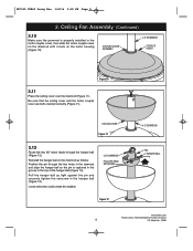
...the three blade assemblies will be adjusted by loosening the Phillips head setscrew in Step 3.12. Loosely fasten each hole (Figure 5). BP7515 CF860 Luray Eco 1/4/16 2:35 PM Page 7 3. Repeat the washer head screw installation for reinstallation in the hanger ball until the ball falls freely ... 4.5" DOWNROD HANGER BALL PHILLIPS HEAD SETSCREW (LOOSENED) emersonfans.com Please contact 1-800-654-3545 for further assistance 7 ETL Model No.: CF860 Remove the pin from the 4.5" downrod, then remove the hanger ball (Figure 6). Have patience during this step: Align the two blade...
...the three blade assemblies will be adjusted by loosening the Phillips head setscrew in Step 3.12. Loosely fasten each hole (Figure 5). BP7515 CF860 Luray Eco 1/4/16 2:35 PM Page 7 3. Repeat the washer head screw installation for reinstallation in the hanger ball until the ball falls freely ... 4.5" DOWNROD HANGER BALL PHILLIPS HEAD SETSCREW (LOOSENED) emersonfans.com Please contact 1-800-654-3545 for further assistance 7 ETL Model No.: CF860 Remove the pin from the 4.5" downrod, then remove the hanger ball (Figure 6). Have patience during this step: Align the two blade...

Owner Manual
Page 8
...HEAD SETSCREWS (2) Figure 8 3.9 Align the clevis pin holes in the downrod with the holes in the motor coupler for installation of the downrod (Figure 8). BP7515 CF860 Luray Eco 1/4/16 2:35 PM Page 8 3. TWO 80" MOTOR LEADS (UNTWISTED) Figure 7 3.8 Loosen the two Phillips head setscrews in the motor coupler. WARNING It... is properly installed and securely tightened. Figure 9 8 4.5" DOWNROD 4.5" DOWNROD MOTOR COUPLING MOTOR COUPLING HAIRPIN CLIP ETL Model No.: CF860 Route the two motor leads through the holes in the motor coupler (Figure 8).
...HEAD SETSCREWS (2) Figure 8 3.9 Align the clevis pin holes in the downrod with the holes in the motor coupler for installation of the downrod (Figure 8). BP7515 CF860 Luray Eco 1/4/16 2:35 PM Page 8 3. TWO 80" MOTOR LEADS (UNTWISTED) Figure 7 3.8 Loosen the two Phillips head setscrews in the motor coupler. WARNING It... is properly installed and securely tightened. Figure 9 8 4.5" DOWNROD 4.5" DOWNROD MOTOR COUPLING MOTOR COUPLING HAIRPIN CLIP ETL Model No.: CF860 Route the two motor leads through the holes in the motor coupler (Figure 8).
Owner Manual
Page 9
... fan wobble. 4.5" DOWNROD PHILLIPS HEAD SETSCREW Figure 12 4.5" DOWNROD PIN HANGER BALL emersonfans.com Please contact 1-800-654-3545 for further assistance 9 ETL Model No.: CF860 BP7515 CF860 Luray Eco 1/4/16 2:35 PM Page 9 3.
... fan wobble. 4.5" DOWNROD PHILLIPS HEAD SETSCREW Figure 12 4.5" DOWNROD PIN HANGER BALL emersonfans.com Please contact 1-800-654-3545 for further assistance 9 ETL Model No.: CF860 BP7515 CF860 Luray Eco 1/4/16 2:35 PM Page 9 3.

Owner Manual
Page 10
CEILING ! AT LEAST 7' ! BP7515 CF860 Luray Eco 1/4/16 2:35 PM Page 10 3. Measure up approximately 6 to Hang Your Ceiling Fan ! Cut off wall switch is grounded, contact a licensed electrician for safe operation. ... off at the main fuse box before wiring. WARNING To avoid possible electrical shock, be done or approved by a licensed electrician. 10 ETL Model No.: CF860 Ceiling Fan Assembly (Continued) 3.13 The fan comes with black and white leads that are not sure if the outlet box is not sufficient. Figure...
CEILING ! AT LEAST 7' ! BP7515 CF860 Luray Eco 1/4/16 2:35 PM Page 10 3. Measure up approximately 6 to Hang Your Ceiling Fan ! Cut off wall switch is grounded, contact a licensed electrician for safe operation. ... off at the main fuse box before wiring. WARNING To avoid possible electrical shock, be done or approved by a licensed electrician. 10 ETL Model No.: CF860 Ceiling Fan Assembly (Continued) 3.13 The fan comes with black and white leads that are not sure if the outlet box is not sufficient. Figure...

Owner Manual
Page 11
NOTE: CEILING COVER, SUPPLY WIRES AND FAN WIRES OMITTED FOR CLARITY. BP7515 CF860 Luray Eco 1/4/16 2:35 PM Page 11 4. How to bend the blade assemblies while hanging the partially assembled ceiling fan. ! outlet box listed as "Acceptable for Fan ... to electrical wires and possible shock or fire hazard. If bracket and/or outlet box are not acceptable for further assistance 11 ETL Model No.: CF860 If the outlet box is engaged with the outlet box. (Figure 15). NOTE: Be very careful not to Hang Your Ceiling Fan (Continued) ! OUTLET BOX...
NOTE: CEILING COVER, SUPPLY WIRES AND FAN WIRES OMITTED FOR CLARITY. BP7515 CF860 Luray Eco 1/4/16 2:35 PM Page 11 4. How to bend the blade assemblies while hanging the partially assembled ceiling fan. ! outlet box listed as "Acceptable for Fan ... to electrical wires and possible shock or fire hazard. If bracket and/or outlet box are not acceptable for further assistance 11 ETL Model No.: CF860 If the outlet box is engaged with the outlet box. (Figure 15). NOTE: Be very careful not to Hang Your Ceiling Fan (Continued) ! OUTLET BOX...
Owner Manual
Page 12
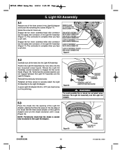
... ADAPTER PAN HEAD SCREW ! Figure 19 ROTATE CLOCKWISE LIGHT KIT ADAPTER RAISED DIMPLES (3) SHADE FLAT AREA OF SHADE (3) 12 ETL Model No.: CF860 Retain the screw for future use. Rotate the Light Kit Assembly counter-clockwise to the Light Kit Adapter. NOTE: Periodically check that the serrated... until it stops (Figure 19). Verify that the shade is in the Light Kit Adapter and loosen the remaining two screws (Figure 17). BP7515 CF860 Luray Eco 1/4/16 2:35 PM Page 12 5. The connection is complete when you hear a soft click. WARNING To avoid possible fire or shock, do...
... ADAPTER PAN HEAD SCREW ! Figure 19 ROTATE CLOCKWISE LIGHT KIT ADAPTER RAISED DIMPLES (3) SHADE FLAT AREA OF SHADE (3) 12 ETL Model No.: CF860 Retain the screw for future use. Rotate the Light Kit Assembly counter-clockwise to the Light Kit Adapter. NOTE: Periodically check that the serrated... until it stops (Figure 19). Verify that the shade is in the Light Kit Adapter and loosen the remaining two screws (Figure 17). BP7515 CF860 Luray Eco 1/4/16 2:35 PM Page 12 5. The connection is complete when you hear a soft click. WARNING To avoid possible fire or shock, do...

Owner Manual
Page 13
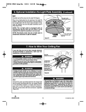
... wire connector into the white wire connector of Light Kit Assembly. Store Shade in the parts bag. Retain for further assistance 13 ETL Model No.: CF860 Optional Installation of No-Light Plate Assembly 6.1 Removal of the Light Kit Assembly from the Light Kit Adapter: Loosened the Light Kit Adapterr #6-32 ... screw heads in the key hole slots. Rotate the Light Kit Assembly clockwise to loosen from the Light Kit Adapter (Figure 20). BP7515 CF860 Luray Eco 1/4/16 2:35 PM Page 13 6. Store Light Kit Assembly in a safe location for removal of the Light Kit Assembly (Figure 22).
... wire connector into the white wire connector of Light Kit Assembly. Store Shade in the parts bag. Retain for further assistance 13 ETL Model No.: CF860 Optional Installation of No-Light Plate Assembly 6.1 Removal of the Light Kit Assembly from the Light Kit Adapter: Loosened the Light Kit Adapterr #6-32 ... screw heads in the key hole slots. Rotate the Light Kit Assembly clockwise to loosen from the Light Kit Adapter (Figure 20). BP7515 CF860 Luray Eco 1/4/16 2:35 PM Page 13 6. Store Light Kit Assembly in a safe location for removal of the Light Kit Assembly (Figure 22).
Owner Manual
Page 14
...LISTED WIRE CONNECTOR GREEN WIRE (GROUND) FROM HANGER BALL GREEN WIRE (GROUND) FROM HANGER BRACKET Figure 24 ! could result in Light Kit Adapter. BP7515 CF860 Luray Eco 1/4/16 2:35 PM Page 14 6. NOTE: The no -light plate with green colored insulation). WARNING To avoid possible electrical shock, be sure electricity... wires into the opening of the Light Kit Adapter, aligning the three flat areas on the top edge of supply (this product by Emerson Electric Co. Figure 23 ROTATE CLOCKWISE NO-LIGHT PLATE INTERFERENCE DEVICE LIGHT KIT ADAPTER RAISED DIMPLES (3) NO-LIGHT PLATE FLAT AREA OF NO...
...LISTED WIRE CONNECTOR GREEN WIRE (GROUND) FROM HANGER BALL GREEN WIRE (GROUND) FROM HANGER BRACKET Figure 24 ! could result in Light Kit Adapter. BP7515 CF860 Luray Eco 1/4/16 2:35 PM Page 14 6. NOTE: The no -light plate with green colored insulation). WARNING To avoid possible electrical shock, be sure electricity... wires into the opening of the Light Kit Adapter, aligning the three flat areas on the top edge of supply (this product by Emerson Electric Co. Figure 23 ROTATE CLOCKWISE NO-LIGHT PLATE INTERFERENCE DEVICE LIGHT KIT ADAPTER RAISED DIMPLES (3) NO-LIGHT PLATE FLAT AREA OF NO...

Owner Manual
Page 15
...) LISTED WIRE CONNECTOR Figure 25 7.3 Securely connect the fan motor black wire to the supply black (hot) wire using wire connector (supplied) (Figure 25). BP7515 CF860 Luray Eco 1/4/16 2:35 PM Page 15 7. WHITE WIRES Figure 27 BLACK WIRES emersonfans.com Please contact 1-800-654-3545 for the ground wire. GREEN WIRES ! Noise...
...) LISTED WIRE CONNECTOR Figure 25 7.3 Securely connect the fan motor black wire to the supply black (hot) wire using wire connector (supplied) (Figure 25). BP7515 CF860 Luray Eco 1/4/16 2:35 PM Page 15 7. WHITE WIRES Figure 27 BLACK WIRES emersonfans.com Please contact 1-800-654-3545 for the ground wire. GREEN WIRES ! Noise...

Owner Manual
Page 16
... until studs protrude through the holes in the hanger bracket (Figure 28). Figure 29 CEILING COVER THREADED STUDS (2) LOCKWASHERS (2) KNURLED KNOBS (2) 16 ETL Model No.: CF860 THREADED STUDS (2) Figure 28 7.6 Lift the ceiling cover up to Wire Your Ceiling Fan (Continued) 7.5 Screw the two threaded studs (supplied) into the tapped holes... against the ceiling and the hole in place by sliding lockwashers over the threaded studs and installing the two knurled knobs (supplied). (Figure 29). BP7515 CF860 Luray Eco 1/4/16 2:35 PM Page 16 7.
... until studs protrude through the holes in the hanger bracket (Figure 28). Figure 29 CEILING COVER THREADED STUDS (2) LOCKWASHERS (2) KNURLED KNOBS (2) 16 ETL Model No.: CF860 THREADED STUDS (2) Figure 28 7.6 Lift the ceiling cover up to Wire Your Ceiling Fan (Continued) 7.5 Screw the two threaded studs (supplied) into the tapped holes... against the ceiling and the hole in place by sliding lockwashers over the threaded studs and installing the two knurled knobs (supplied). (Figure 29). BP7515 CF860 Luray Eco 1/4/16 2:35 PM Page 16 7.

Owner Manual
Page 17
... x .375" pan head screw (Figure 31). WARNING Turning off at the main fuse box before wiring. Retain shade for further assistance 17 ETL Model No.: CF860 REPLACING THE ENTIRE LIGHT KIT ASSEMBLY. ! BP7515 CF860 Luray Eco 1/4/16 2:35 PM Page 17 8.
... x .375" pan head screw (Figure 31). WARNING Turning off at the main fuse box before wiring. Retain shade for further assistance 17 ETL Model No.: CF860 REPLACING THE ENTIRE LIGHT KIT ASSEMBLY. ! BP7515 CF860 Luray Eco 1/4/16 2:35 PM Page 17 8.

Owner Manual
Page 18
... Driver Assembly. If Replacing Only the LED Array, Proceed to unstick the adhesive foam tape from the black wire connector of the Light Kit. BP7515 CF860 Luray Eco 1/4/16 2:35 PM Page 18 8. FAN MOTOR ASSEMBLY BLACK WIRE CONNECTOR FAN MOTOR ASSEMBLY WHITE WIRE CONNECTOR LIGHT KIT ASSEMBLY BLACK WIRE CONNECTOR LIGHT KIT... of the Light Kit Assembly Array connector (Figure 33). LIGHT KIT ASSEMBLY DRIVER LIGHT KIT ASSEMBLY ADHESIVE FOAM TAPE Figure 34 18 ETL Model No.: CF860
... Driver Assembly. If Replacing Only the LED Array, Proceed to unstick the adhesive foam tape from the black wire connector of the Light Kit. BP7515 CF860 Luray Eco 1/4/16 2:35 PM Page 18 8. FAN MOTOR ASSEMBLY BLACK WIRE CONNECTOR FAN MOTOR ASSEMBLY WHITE WIRE CONNECTOR LIGHT KIT ASSEMBLY BLACK WIRE CONNECTOR LIGHT KIT... of the Light Kit Assembly Array connector (Figure 33). LIGHT KIT ASSEMBLY DRIVER LIGHT KIT ASSEMBLY ADHESIVE FOAM TAPE Figure 34 18 ETL Model No.: CF860

Owner Manual
Page 19
... CONNECTOR CONNECTOR LIGHT KIT ASSEMBLY LIGHT KIT ASSEMBLY DRIVER Figure 36 emersonfans.com Please contact 1-800-654-3545 for further assistance 19 ETL Model No.: CF860 BP7515 CF860 Luray Eco 1/4/16 2:35 PM Page 19 8.
... CONNECTOR CONNECTOR LIGHT KIT ASSEMBLY LIGHT KIT ASSEMBLY DRIVER Figure 36 emersonfans.com Please contact 1-800-654-3545 for further assistance 19 ETL Model No.: CF860 BP7515 CF860 Luray Eco 1/4/16 2:35 PM Page 19 8.

Owner Manual
Page 20
... PIN ARRAY CONNECTOR CONNECTOR LIGHT KIT ASSEMBLY LIGHT KIT ASSEMBLY DRIVER Figure 39 20 ETL Model No.: CF860 Discard the Light Kit Assembly Array and three plastic screws in the correct recycle bin. BP7515 CF860 Luray Eco 1/4/16 2:35 PM Page 20 8. PLASTIC PHILLIPS HEAD SCREWS (3) LIGHT KIT ASSEMBLY ARRAY LIGHT KIT ASSEMBLY Figure...
... PIN ARRAY CONNECTOR CONNECTOR LIGHT KIT ASSEMBLY LIGHT KIT ASSEMBLY DRIVER Figure 39 20 ETL Model No.: CF860 Discard the Light Kit Assembly Array and three plastic screws in the correct recycle bin. BP7515 CF860 Luray Eco 1/4/16 2:35 PM Page 20 8. PLASTIC PHILLIPS HEAD SCREWS (3) LIGHT KIT ASSEMBLY ARRAY LIGHT KIT ASSEMBLY Figure...