
Owner Manual
Page 2
.... Installation of Glass Shade 27-28 11. Interchanging Fan Blades on Installed Fan 37-38 17. Maintenance 41 20. How to Wire Your Ceiling Fan 20-24 9. Using Your Ceiling Fan 35-36 16. Remote Control Trouble Shooting 40 19. Repair Parts 42-43 Warranty 44 Tommy Bahama • 04/2013 2 [email protected] • 1-800-875-3545 Ceiling Fan Location 5 3. Receiver Code Leaning - Installation of the Storage Bracket 34 15. Preparation 4 2. Electrical Requirements 6 4. How to Assemble Your Light Kit...
.... Installation of Glass Shade 27-28 11. Interchanging Fan Blades on Installed Fan 37-38 17. Maintenance 41 20. How to Wire Your Ceiling Fan 20-24 9. Using Your Ceiling Fan 35-36 16. Remote Control Trouble Shooting 40 19. Repair Parts 42-43 Warranty 44 Tommy Bahama • 04/2013 2 [email protected] • 1-800-875-3545 Ceiling Fan Location 5 3. Receiver Code Leaning - Installation of the Storage Bracket 34 15. Preparation 4 2. Electrical Requirements 6 4. How to Assemble Your Light Kit...
Owner Manual
Page 3
... necessary before installing light kit. Substitution of wiring your owner's manual carefully and keep it for future use with this data above and keep it in wet locations". Additional Safety Instructions for use with this product and/or any solid-state speed control device. outlet boxes listed as "Acceptable for use . WARNING: This product is to be in between rotating fan blades. Use this fan with the fan blades. 5. or less...
... necessary before installing light kit. Substitution of wiring your owner's manual carefully and keep it for future use with this data above and keep it in wet locations". Additional Safety Instructions for use with this product and/or any solid-state speed control device. outlet boxes listed as "Acceptable for use . WARNING: This product is to be in between rotating fan blades. Use this fan with the fan blades. 5. or less...
Owner Manual
Page 4
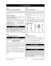
... mm Box Wrench 1.3 Unpacking Instructions 1.4 Optional Accessories ! WARNING The use fan if any hardware or components are designed to 50 ft. / 15.2 m. 50-100 ft. / 15.2-30.4 m. WARNING Do not install or use of This Manual Read the entire manual before installation. Each step has three components: 1. New parts will be shipped free of wiring your home or office. To order Remote Wall Control TBSW102, go to the Hardware Guide...
... mm Box Wrench 1.3 Unpacking Instructions 1.4 Optional Accessories ! WARNING The use fan if any hardware or components are designed to 50 ft. / 15.2 m. 50-100 ft. / 15.2-30.4 m. WARNING Do not install or use of This Manual Read the entire manual before installation. Each step has three components: 1. New parts will be shipped free of wiring your home or office. To order Remote Wall Control TBSW102, go to the Hardware Guide...
Owner Manual
Page 5
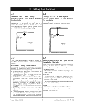
... essential for installation in order to accommodate the remote control receiver. above , have a licensed electrician install the required outlet box. • The outlet box must be mounted to determine if the site is designed for your ceiling outlet box is not marked as walls, or posts, within 30 in . / 0.3 cm. high. • The fan blades have a sloped ceiling. ceilings, even when a light kit is rated for safety, reliable operation, maximum efficiency...
... essential for installation in order to accommodate the remote control receiver. above , have a licensed electrician install the required outlet box. • The outlet box must be mounted to determine if the site is designed for your ceiling outlet box is not marked as walls, or posts, within 30 in . / 0.3 cm. high. • The fan blades have a sloped ceiling. ceilings, even when a light kit is rated for safety, reliable operation, maximum efficiency...
Owner Manual
Page 8
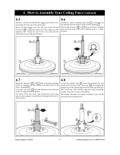
... motor wires protruding from working loose. 2b or 3 24 e 23 24 Tommy Bahama • 04/2013 8 [email protected] • 1-800-875-3545 Locate the clevis pin 24 from the hardware kit and install it into the end of the selected downrod 2b or 3 and push until they do not protrude into the aligned mounting holes. Route all three motor wires...
... motor wires protruding from working loose. 2b or 3 24 e 23 24 Tommy Bahama • 04/2013 8 [email protected] • 1-800-875-3545 Locate the clevis pin 24 from the hardware kit and install it into the end of the selected downrod 2b or 3 and push until they do not protrude into the aligned mounting holes. Route all three motor wires...
Owner Manual
Page 11
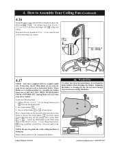
... the downrod 2b or 3 . to Assemble Your Ceiling Fan (Continued) 4.16 Grasp the motor wires and pull them straight up . Assemble five blades from one set you want for the remaining four blades. ! WARNING To reduce the risk of the blade as instructed below. Cut all three wires 6 in . / 22.9 cm. 2a 2b or 3 4.17 NOTE: Your fan is facing up above the hanger ball 2a using...
... the downrod 2b or 3 . to Assemble Your Ceiling Fan (Continued) 4.16 Grasp the motor wires and pull them straight up . Assemble five blades from one set you want for the remaining four blades. ! WARNING To reduce the risk of the blade as instructed below. Cut all three wires 6 in . / 22.9 cm. 2a 2b or 3 4.17 NOTE: Your fan is facing up above the hanger ball 2a using...
Owner Manual
Page 12
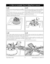
... fan housing assembly has five rubber spacers f that protect the housing during shipping. Discard the spacers and spacer screws. 4 f 4 4.20 Locate a blade assembly and slide the end of the blade assemblies. These spacers must be necessary to stack both blade holder screws. 4.21 Rotate the motor and install each of the shipping carton to allow installation of the blade holder onto the motor hub. Use the switch plate viewing window to loosen and remove...
... fan housing assembly has five rubber spacers f that protect the housing during shipping. Discard the spacers and spacer screws. 4 f 4 4.20 Locate a blade assembly and slide the end of the blade assemblies. These spacers must be necessary to stack both blade holder screws. 4.21 Rotate the motor and install each of the shipping carton to allow installation of the blade holder onto the motor hub. Use the switch plate viewing window to loosen and remove...

Owner Manual
Page 13
...-3545 Light Fitter Assembly 10b . 5.2 Locate and remove the small orange wire connectors 10c attached to install the light kit assembly on a padded work surface. Skip to Section 6 if you will find a hex nut h (1/8-27 NPS) and i lock washer. Position it , reverse Section 6 assembly instructions to uninstall the light kit assembly and then follow the below instructions. How to disassemble the light fixture from the Fan This ceiling fan can be sure electricity is turned off wall switch...
...-3545 Light Fitter Assembly 10b . 5.2 Locate and remove the small orange wire connectors 10c attached to install the light kit assembly on a padded work surface. Skip to Section 6 if you will find a hex nut h (1/8-27 NPS) and i lock washer. Position it , reverse Section 6 assembly instructions to uninstall the light kit assembly and then follow the below instructions. How to disassemble the light fixture from the Fan This ceiling fan can be sure electricity is turned off wall switch...
Owner Manual
Page 15
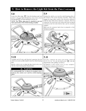
... to Remove the Light Kit from the Fan (Continued) 5.8 Locate the rubber plug 25 from the hardware pack and install it into the blade installation slot of the switch housing plate j by firmly pushing it onto the switch housing plate. Make sure the connector latch closes to properly to align the three holes in the cover with the large white motor electrical connector. 5. How to Section 7. ! The two connectors are keyed and color-coded...
... to Remove the Light Kit from the Fan (Continued) 5.8 Locate the rubber plug 25 from the hardware pack and install it into the blade installation slot of the switch housing plate j by firmly pushing it onto the switch housing plate. Make sure the connector latch closes to properly to align the three holes in the cover with the large white motor electrical connector. 5. How to Section 7. ! The two connectors are keyed and color-coded...
Owner Manual
Page 16
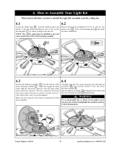
... white motor electrical connector. WARNING To avoid possible fire or shock, do not pinch wires between the switch housing/light kit assembly and the switch housing plate. 10 10 4 4 Tommy Bahama • 04/2013 16 [email protected] • 1-800-875-3545 flat head screws 22 from the hardware pack and install it into the slot. Spin the light kit assembly 10 to install the Light Kit Assembly onto the ceiling fan. 6.1 Locate the rubber plug...
... white motor electrical connector. WARNING To avoid possible fire or shock, do not pinch wires between the switch housing/light kit assembly and the switch housing plate. 10 10 4 4 Tommy Bahama • 04/2013 16 [email protected] • 1-800-875-3545 flat head screws 22 from the hardware pack and install it into the slot. Spin the light kit assembly 10 to install the Light Kit Assembly onto the ceiling fan. 6.1 Locate the rubber plug...
Owner Manual
Page 18
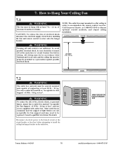
... Local codes and the ceiling fan must mounted to a flat ceiling in doubt. Consult a qualified electrician if in order to install the ceiling fan hanger bracket on the outlet box. Most outlet boxes commonly used for Fan Support of electrical shock, disconnect the electrical supply circuit before installing the fan and remote control receiver onto the hanger bracket.. How to discuss optional control methods, and sloped ceiling installation. NOTE: The outlet box must be sure electricity is turned off wall switch is...
... Local codes and the ceiling fan must mounted to a flat ceiling in doubt. Consult a qualified electrician if in order to install the ceiling fan hanger bracket on the outlet box. Most outlet boxes commonly used for Fan Support of electrical shock, disconnect the electrical supply circuit before installing the fan and remote control receiver onto the hanger bracket.. How to discuss optional control methods, and sloped ceiling installation. NOTE: The outlet box must be sure electricity is turned off wall switch is...
Owner Manual
Page 19
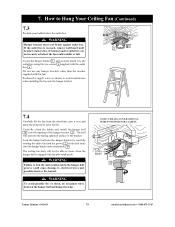
... entire fan until bracket contacts box. If bracket and/or outlet box are not securely attached, the fan could cause damage to avoid interference when installing the fan onto the hanger bracket. How to the outlet box using the two screws k supplied with this fan. WARNING Hanger bracket must seat firmly against outlet box. If the outlet box is engaged with the anti-rotation tab. ! NOTE: CEILING COVER AND FAN WIRES OMITTED...
... entire fan until bracket contacts box. If bracket and/or outlet box are not securely attached, the fan could cause damage to avoid interference when installing the fan onto the hanger bracket. How to the outlet box using the two screws k supplied with this fan. WARNING Hanger bracket must seat firmly against outlet box. If the outlet box is engaged with the anti-rotation tab. ! NOTE: CEILING COVER AND FAN WIRES OMITTED...
Owner Manual
Page 23
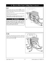
Install the connector using the technique described in place. TO MOTOR N NOTE: Failure to the receiver blue wire marked "FOR LIGHT". WARNING AC IN L Check to ensure it non-operable. Noise and fan damage could result. 12c 8.10 After wire connections have been made, separate the grounded white neutral and green wires on one side of the outlet box n . 1 TO MOTOR L AC IN N TO MOTOR N AC IN...
Install the connector using the technique described in place. TO MOTOR N NOTE: Failure to the receiver blue wire marked "FOR LIGHT". WARNING AC IN L Check to ensure it non-operable. Noise and fan damage could result. 12c 8.10 After wire connections have been made, separate the grounded white neutral and green wires on one side of the outlet box n . 1 TO MOTOR L AC IN N TO MOTOR N AC IN...
Owner Manual
Page 33
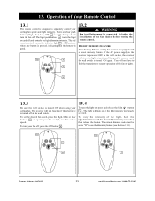
... ceiling fan receiver is good. 12a t Med Low v High Off 13.2 ! The remote dimmer code must be set to "D" to separately control your fan on , press and release the light ( ) button w . Operation of the fan blades, before testing the remote control. The light push button w turns the light on at the light intensity previously selected. If the AC power supply to operate your ceiling fan speed and light intensity. To set the fan speed and turn your ceiling fan. The red remote control transmitter indicator light...
... ceiling fan receiver is good. 12a t Med Low v High Off 13.2 ! The remote dimmer code must be set to "D" to separately control your fan on , press and release the light ( ) button w . Operation of the fan blades, before testing the remote control. The light push button w turns the light on at the light intensity previously selected. If the AC power supply to operate your ceiling fan speed and light intensity. To set the fan speed and turn your ceiling fan. The red remote control transmitter indicator light...
Owner Manual
Page 35
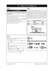
... light control button. One downrod of the switch cover just below the blade holders. Press and release the light button to circulate air downward. pan head shoulder screw 18 . 18 3. 15. Using Your Ceiling Fan 15.1 ! The switch is located on the work surface: 3 1. pan head screw 19 (if light kit was installed). 4. pan head shoulder screw 19 20 with a soft rubber seal that protects it from the factory with the reversing switch...
... light control button. One downrod of the switch cover just below the blade holders. Press and release the light button to circulate air downward. pan head shoulder screw 18 . 18 3. 15. Using Your Ceiling Fan 15.1 ! The switch is located on the work surface: 3 1. pan head screw 19 (if light kit was installed). 4. pan head shoulder screw 19 20 with a soft rubber seal that protects it from the factory with the reversing switch...
Owner Manual
Page 37
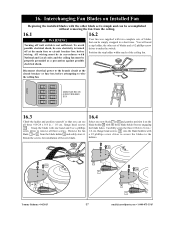
... electrical power to the branch circuit at the main fuse or circuit breaker box before attempting to make the switch. flange head screws 18 into the blade holders with National and Local codes and the ceiling fan must be properly grounded as a precaution against possible electrical shock. Your fan was supplied with two complete sets of blades and a #2 phillips screw driver to wire the ceiling fan. Interchanging Fan Blades on the blade...
... electrical power to the branch circuit at the main fuse or circuit breaker box before attempting to make the switch. flange head screws 18 into the blade holders with National and Local codes and the ceiling fan must be properly grounded as a precaution against possible electrical shock. Your fan was supplied with two complete sets of blades and a #2 phillips screw driver to wire the ceiling fan. Interchanging Fan Blades on the blade...
Owner Manual
Page 39
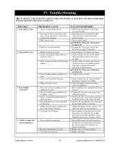
.... 2. Hanger bracket and/or ceiling outlet box is weak. 3. Remote control battery is not securely fastened. 6. Check main and branch circuit fuses or circuit breakers. 2. Check to make sure the screws which attach the fan blade holders to the motor are tight. 4. Check the hanger bracket mounting screws for proper installation. 2. Tighten the hanger bracket screws to fan. 2. 17. TROUBLE 1. Fan will not illuminate. Wall switch is turned off . 4. Screws holding blades to fan and switch wire connections in the hanger ball/ downrod assembly...
.... 2. Hanger bracket and/or ceiling outlet box is weak. 3. Remote control battery is not securely fastened. 6. Check main and branch circuit fuses or circuit breakers. 2. Check to make sure the screws which attach the fan blade holders to the motor are tight. 4. Check the hanger bracket mounting screws for proper installation. 2. Tighten the hanger bracket screws to fan. 2. 17. TROUBLE 1. Fan will not illuminate. Wall switch is turned off . 4. Screws holding blades to fan and switch wire connections in the hanger ball/ downrod assembly...
Owner Manual
Page 42
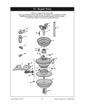
Repair Parts Please see page 43 for parts table. Use these part numbers only when ordering repair parts 16 Med Low High Off 15 17 28 20 18 19 21 23 8 9 10 27 24 26 1 2 4 3 6 7 22 5 11 25 12 14 13 Tommy Bahama • 04/2013 42 [email protected] • 1-800-875-3545 These parts numbers shown below do not correspond to the assembly instruction identification numbers found within this manual and parts/hardware guide. 21.
Repair Parts Please see page 43 for parts table. Use these part numbers only when ordering repair parts 16 Med Low High Off 15 17 28 20 18 19 21 23 8 9 10 27 24 26 1 2 4 3 6 7 22 5 11 25 12 14 13 Tommy Bahama • 04/2013 42 [email protected] • 1-800-875-3545 These parts numbers shown below do not correspond to the assembly instruction identification numbers found within this manual and parts/hardware guide. 21.

Owner Manual
Page 43
... 764076 - - - - - Use these part numbers only when ordering repair parts Please see page 42 for one fan) 11 Wiring Harness Assembly 12 Light Kit Assembly 13 Finial Nut with Rubber Washer and Hex Nut 14 Glass Shade 15 Transmitter TBSR135 with Cradle and Screws 16 Receiver TBSW100 with Washer (1 piece) 25 Screw, Flat Head, #8-32 x 0.3 in . / 1.3 cm. Repair Parts (Continued) These parts numbers do not correspond to the assembly instruction identification numbers found within this manual and parts/hardware guide. Wet Location * Hardware...
... 764076 - - - - - Use these part numbers only when ordering repair parts Please see page 42 for one fan) 11 Wiring Harness Assembly 12 Light Kit Assembly 13 Finial Nut with Rubber Washer and Hex Nut 14 Glass Shade 15 Transmitter TBSR135 with Cradle and Screws 16 Receiver TBSW100 with Washer (1 piece) 25 Screw, Flat Head, #8-32 x 0.3 in . / 1.3 cm. Repair Parts (Continued) These parts numbers do not correspond to the assembly instruction identification numbers found within this manual and parts/hardware guide. Wet Location * Hardware...
Owner Manual
Page 44
... original purchaser or user ceases to avoid damage in China 04/13 Form No. What Is Not Covered: The glass globes and light bulbs of the nearest authorized service center. Do To Correct Problems: Emerson Electric Co. Incidental damages include but are not limited to the cost of repairing or replacing other accessory at no charge to you purchased your ceiling fan are not covered by Emerson Electric Co., • Mishandling, improper installation...
... original purchaser or user ceases to avoid damage in China 04/13 Form No. What Is Not Covered: The glass globes and light bulbs of the nearest authorized service center. Do To Correct Problems: Emerson Electric Co. Incidental damages include but are not limited to the cost of repairing or replacing other accessory at no charge to you purchased your ceiling fan are not covered by Emerson Electric Co., • Mishandling, improper installation...


