

Owner Manual
Page 1
F40BP72890001 Form No. READ AND SAVE THESE INSTRUCTIONS xxxxxxxxxxxxxxxxxxxxxxxxxxxxxxxxxxxxxxxxxxxxxxxxxxx xxxxxxxxxxxxxxxxxxxxxxxxxxxxxxxxxxxxxxxxxxxxxxxxxxxxxxxxxxxxx xxxxxxxxxxxxxxxxxxxxxxxxxxxxxxxxxxxxxxxxxxxxxxxxxxxxxxxxxxxxx BAHAMA BREEZES Damp Location Ceiling Fan Owner's Manual Model Numbers TB344AP00 TB344DBZ00 Antique Pewter Housing Distressed Bronze Housing Net Weight: 19.0 Lbs. xxxxxxxxxxxxxxxxxxxxxxxxxxxxxxxxxxxxxxxxxxxxxxxxxxx Part No. BP7289-1
F40BP72890001 Form No. READ AND SAVE THESE INSTRUCTIONS xxxxxxxxxxxxxxxxxxxxxxxxxxxxxxxxxxxxxxxxxxxxxxxxxxx xxxxxxxxxxxxxxxxxxxxxxxxxxxxxxxxxxxxxxxxxxxxxxxxxxxxxxxxxxxxx xxxxxxxxxxxxxxxxxxxxxxxxxxxxxxxxxxxxxxxxxxxxxxxxxxxxxxxxxxxxx BAHAMA BREEZES Damp Location Ceiling Fan Owner's Manual Model Numbers TB344AP00 TB344DBZ00 Antique Pewter Housing Distressed Bronze Housing Net Weight: 19.0 Lbs. xxxxxxxxxxxxxxxxxxxxxxxxxxxxxxxxxxxxxxxxxxxxxxxxxxx Part No. BP7289-1
Owner Manual
Page 2
... use with the National Electrical Code, ANSI/NFPA 70-2011 and Local Codes. The fan must be sure electricity is to be mounted with the fan blades at the fuse box before wiring, and do not use a Tommy Bahama or any accessories designated specifically for future reference. 2. could result in between rotating fan blades. Use only U.L. Most outlet boxes commonly used for future use with solid-state speed controls. Follow the recommended instructions for fan support...
... use with the National Electrical Code, ANSI/NFPA 70-2011 and Local Codes. The fan must be sure electricity is to be mounted with the fan blades at the fuse box before wiring, and do not use a Tommy Bahama or any accessories designated specifically for future reference. 2. could result in between rotating fan blades. Use only U.L. Most outlet boxes commonly used for future use with solid-state speed controls. Follow the recommended instructions for fan support...
Owner Manual
Page 3
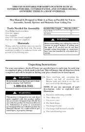
... wrench (supplied) Four wire connectors (supplied) Materials Wiring, outlet box and box connectors must be a 3-conductor (2-wire with this product by Emerson Electric Co. One switch housing cover 3 The minimum wire would be of type required by a licensed electrician. One motor cover d. Substitution of the following parts: NOTE: If you be helpful in finding your fan installed by the local code. One hanger bracket f. Unpacking Instructions For your fan (page 9). This Manual Is Designed to Make...
... wrench (supplied) Four wire connectors (supplied) Materials Wiring, outlet box and box connectors must be a 3-conductor (2-wire with this product by Emerson Electric Co. One switch housing cover 3 The minimum wire would be of type required by a licensed electrician. One motor cover d. Substitution of the following parts: NOTE: If you be helpful in finding your fan installed by the local code. One hanger bracket f. Unpacking Instructions For your fan (page 9). This Manual Is Designed to Make...
Owner Manual
Page 4
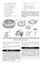
... 50 pounds. ! WARNING Turning off wall switch is turned off at the main fuse or circuit breaker box at the main fuse or circuit breaker box before proceeding. Two couplings 11. Most outlet boxes commonly used for Fan Support of light fixtures are missing, contact your fan is to replace an existing ceiling light fixture, turn electricity off at this time and remove the existing light fixture. ! Consult a qualified electrician if...
... 50 pounds. ! WARNING Turning off wall switch is turned off at the main fuse or circuit breaker box at the main fuse or circuit breaker box before proceeding. Two couplings 11. Most outlet boxes commonly used for Fan Support of light fixtures are missing, contact your fan is to replace an existing ceiling light fixture, turn electricity off at this time and remove the existing light fixture. ! Consult a qualified electrician if...
Owner Manual
Page 5
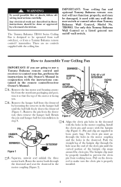
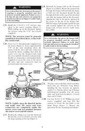
... installed. 5 WARNING To avoid possible fire or shock, follow all wiring instructions carefully. Any electrical work not described in step 8. Remove the fan motor and housing assembly from the styrofoam packaging and position it used with the hairpin clip (Figure 2). (Pin and clip are going to use a Tommy Bahama remote control and receiver to control your fan, perform the instructions in this Tommy Bahama Wall Control or a listed general use on the downrod...
... installed. 5 WARNING To avoid possible fire or shock, follow all wiring instructions carefully. Any electrical work not described in step 8. Remove the fan motor and housing assembly from the styrofoam packaging and position it used with the hairpin clip (Figure 2). (Pin and clip are going to use a Tommy Bahama remote control and receiver to control your fan, perform the instructions in this Tommy Bahama Wall Control or a listed general use on the downrod...
Owner Manual
Page 6
... pulling up approximately 6 to 9-inches above , or fan wobble could result in the fan falling. 5. Coil the wires and wire connectors around the motor coupling then slide the motor cover over the downrod. Install two lockwashers and knurled knobs (supplied) to secure the cover to the blade flange (Figure 5). Reinstall the hanger ball on the downrod, tighten the setscrew using the 5/32" hex wrench (supplied). Position the ceiling cover...
... pulling up approximately 6 to 9-inches above , or fan wobble could result in the fan falling. 5. Coil the wires and wire connectors around the motor coupling then slide the motor cover over the downrod. Install two lockwashers and knurled knobs (supplied) to secure the cover to the blade flange (Figure 5). Reinstall the hanger ball on the downrod, tighten the setscrew using the 5/32" hex wrench (supplied). Position the ceiling cover...
Owner Manual
Page 7
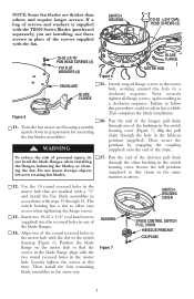
... blades, or cleaning the fan. Use the 10 round recessed holes in the motor hub that the screws in the blade flange align with steps 13 through one of the blade flanges. 14. BUSHING Figure 7 SWITCH HOUSING COVER SPEED CONTROL SWITCH PULL CHAIN HIBISCUS PENDANT COUPLING 7 Failure to allow easy access when tightening the flange screws. 13. SWITCH HOUSING 10-32 x 3/4" OVAL HEAD SCREWS (2) 10-32 x 5/16" PAN HEAD SCREWS (4) #10 FLAT WASHERS (4) FAN BLADE BLADE...
... blades, or cleaning the fan. Use the 10 round recessed holes in the motor hub that the screws in the blade flange align with steps 13 through one of the blade flanges. 14. BUSHING Figure 7 SWITCH HOUSING COVER SPEED CONTROL SWITCH PULL CHAIN HIBISCUS PENDANT COUPLING 7 Failure to allow easy access when tightening the flange screws. 13. SWITCH HOUSING 10-32 x 3/4" OVAL HEAD SCREWS (2) 10-32 x 5/16" PAN HEAD SCREWS (4) #10 FLAT WASHERS (4) FAN BLADE BLADE...
Owner Manual
Page 8
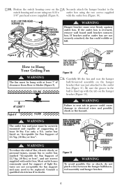
... Hanger bracket must be replaced. 18. with at least 50 lbs. Figure 8 How to the outlet box (Figure 11). WARNING The outlet box and joist must seat firmly against outlet box. Use only a U.L. Most outlet boxes commonly used for Fan Support of clearance from floor to the switch housing and secure using two 8-32 x outlet box using the two screws supplied 3/8" pan head screws (supplied) (Figure 8). NOTE: CEILING COVER, SUPPLY WIRES AND FAN WIRES...
... Hanger bracket must be replaced. 18. with at least 50 lbs. Figure 8 How to the outlet box (Figure 11). WARNING The outlet box and joist must seat firmly against outlet box. Use only a U.L. Most outlet boxes commonly used for Fan Support of clearance from floor to the switch housing and secure using two 8-32 x outlet box using the two screws supplied 3/8" pan head screws (supplied) (Figure 8). NOTE: CEILING COVER, SUPPLY WIRES AND FAN WIRES...
Owner Manual
Page 9
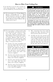
... Control/ Receiver Owner's Manual. d. Securely connect the fan motor blue wire to operate your ceiling fan, wire your fan in place. f. Carefully turn the wires upward and insert them up through the open side of the hanger bracket and into one switch and the ceiling fan from the black, blue and red wires. WARNING Turning off at the wire connectors, except for the ground wire. Securely connect wires with ground) conductor cable between the ceiling and wall outlet boxes. After connections...
... Control/ Receiver Owner's Manual. d. Securely connect the fan motor blue wire to operate your ceiling fan, wire your fan in place. f. Carefully turn the wires upward and insert them up through the open side of the hanger bracket and into one switch and the ceiling fan from the black, blue and red wires. WARNING Turning off at the wire connectors, except for the ground wire. Securely connect wires with ground) conductor cable between the ceiling and wall outlet boxes. After connections...
Owner Manual
Page 10
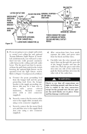
... in the switch housing; b. WARNING Check to control your ceiling fan and optional Tommy Bahama Light Fixture (if installed) simultaneously, you will need a standard two-wire (with a wire connector (supplied). FAN SWITCH LISTED OUTLET BOX GREEN WIRE (GROUND) FROM HANGER BRACKET BLACK GROUND WIRE BLACK FAN WIRE GENERAL PURPOSE ON-OFF WALL RED SWITCHES WHITE BLUE LIGHT SWITCH WHT. Securely connect the fan motor white wire to Figure 13 and proceed as follows: a. Noise and fan damage could result. 10 The fan speed can be operated from the light fixture switch...
... in the switch housing; b. WARNING Check to control your ceiling fan and optional Tommy Bahama Light Fixture (if installed) simultaneously, you will need a standard two-wire (with a wire connector (supplied). FAN SWITCH LISTED OUTLET BOX GREEN WIRE (GROUND) FROM HANGER BRACKET BLACK GROUND WIRE BLACK FAN WIRE GENERAL PURPOSE ON-OFF WALL RED SWITCHES WHITE BLUE LIGHT SWITCH WHT. Securely connect the fan motor white wire to Figure 13 and proceed as follows: a. Noise and fan damage could result. 10 The fan speed can be operated from the light fixture switch...
Owner Manual
Page 11
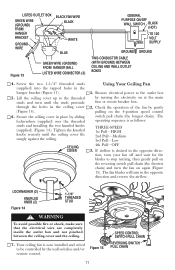
... STUD ! LISTED OUTLET BOX GREEN WIRE (GROUND) FROM HANGER BRACKET GROUND WIRE BLACK FAN WIRE BLACK WHITE BLUE Figure 13 GREEN WIRE (GROUND) FROM HANGER BALL LISTED WIRE CONNECTOR (3) GENERAL PURPOSE ON/OFF WALL SWITCH BLACK (HOT) TO 120 VOLT WHT. Lift the ceiling cover up to the outlet box by the wall switches and/or Figure 15 remote control. 11 SPEED CONTROL SWITCH PULL CHAIN REVERSING SWITCH PULL CHAIN If airflow is as follows: THREE-SPEED 1st Pull-HIGH 2nd Pull-Medium 3rd Pull-Low 4th Pull-OFF 3. Screw the two...
... STUD ! LISTED OUTLET BOX GREEN WIRE (GROUND) FROM HANGER BRACKET GROUND WIRE BLACK FAN WIRE BLACK WHITE BLUE Figure 13 GREEN WIRE (GROUND) FROM HANGER BALL LISTED WIRE CONNECTOR (3) GENERAL PURPOSE ON/OFF WALL SWITCH BLACK (HOT) TO 120 VOLT WHT. Lift the ceiling cover up to the outlet box by the wall switches and/or Figure 15 remote control. 11 SPEED CONTROL SWITCH PULL CHAIN REVERSING SWITCH PULL CHAIN If airflow is as follows: THREE-SPEED 1st Pull-HIGH 2nd Pull-Medium 3rd Pull-Low 4th Pull-OFF 3. Screw the two...
Owner Manual
Page 12
... accessory light kit, remove the two screws securing the switch housing cover on the switch housing. Ceiling Fan Remote Controls (see store or cata- WARNING The use of any accessories designated specifically for your Ceiling Fan Periodic cleaning of your ceiling fan. IMPORTANT CARE INSTRUCTIONS for use water when cleaning your new ceiling fan is the only maintenance that is turned off at the main service box before installing the fan and optional light kit and/or remote control receiver. Attaching Light Kit CAUTION: To reduce the risk of electrical...
... accessory light kit, remove the two screws securing the switch housing cover on the switch housing. Ceiling Fan Remote Controls (see store or cata- WARNING The use of any accessories designated specifically for your Ceiling Fan Periodic cleaning of your ceiling fan. IMPORTANT CARE INSTRUCTIONS for use water when cleaning your new ceiling fan is the only maintenance that is turned off at the main service box before installing the fan and optional light kit and/or remote control receiver. Attaching Light Kit CAUTION: To reduce the risk of electrical...
Owner Manual
Page 13
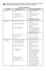
Fan wobbles excessively. Fuse or circuit breaker blown. 2. Wire connectors inside switch housing rattling. 4. Loose screws in smoother operation. Setscrew in motor coupling is not securely fastened. 6. Hanger bracket and/or ceiling outlet box is not tightened securely. 2. SUGGESTED REMEDY 1. Check line power connections to the outlet box, and/or secure outlet box. 6. WARNING: Make sure main power is turned off . 4. Tighten the hanger bracket screws to fan and switch wire connections in switch housing are tight. 3. Fan sounds...
Fan wobbles excessively. Fuse or circuit breaker blown. 2. Wire connectors inside switch housing rattling. 4. Loose screws in smoother operation. Setscrew in motor coupling is not securely fastened. 6. Hanger bracket and/or ceiling outlet box is not tightened securely. 2. SUGGESTED REMEDY 1. Check line power connections to the outlet box, and/or secure outlet box. 6. WARNING: Make sure main power is turned off . 4. Tighten the hanger bracket screws to fan and switch wire connections in switch housing are tight. 3. Fan sounds...

Owner Manual
Page 14
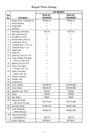
For repair parts, phone 1-800-654-3545. 14 HOW TO ORDER REPAIR PARTS WHEN ORDERING REPAIR PARTS, ALWAYS GIVE THE FOLLOWING INFORMATION: • PART NUMBER • NAME OF ITEM • PART DESCRIPTION • MODEL NUMBER The model number of your Fan will be certain all parts have been removed. Repair Parts 2 4 1 3 8 5 7 6 21 20 6 7 9 22 12 10 13 14 11 23 24 25 15 26 28 27 18 19 17 16 19 Before discarding packaging material, be found on a label attached to the top housing.
For repair parts, phone 1-800-654-3545. 14 HOW TO ORDER REPAIR PARTS WHEN ORDERING REPAIR PARTS, ALWAYS GIVE THE FOLLOWING INFORMATION: • PART NUMBER • NAME OF ITEM • PART DESCRIPTION • MODEL NUMBER The model number of your Fan will be certain all parts have been removed. Repair Parts 2 4 1 3 8 5 7 6 21 20 6 7 9 22 12 10 13 14 11 23 24 25 15 26 28 27 18 19 17 16 19 Before discarding packaging material, be found on a label attached to the top housing.
Owner Manual
Page 15
... x 5/16" (21) 14 Washer, Flat, #10 (21) 15 Screw, Oval Head, #10-32 x 3/4" (11) 16 Screw, Pan Head, #8-32 x 3/8" (2) 17 Pendant, Hibiscus 18 Pendant, Bell 19 Coupling (2) 20 Cover, Ceiling 21 Cover, Motor 22 Capacitor, Aux 10 uF 23 Motor 24 Hub, Motor 25 Flange Set, Blade (full set for one fan) 26 Housing, Switch 27 Cover Assembly, Switch Housing 28 Harness Assembly, Speed/Reverse - Owner's Manual Model No. TB344AP00 761655-42 - - - 762779 Part Numbers Model No. TB344DBZ00 761655...
... x 5/16" (21) 14 Washer, Flat, #10 (21) 15 Screw, Oval Head, #10-32 x 3/4" (11) 16 Screw, Pan Head, #8-32 x 3/8" (2) 17 Pendant, Hibiscus 18 Pendant, Bell 19 Coupling (2) 20 Cover, Ceiling 21 Cover, Motor 22 Capacitor, Aux 10 uF 23 Motor 24 Hub, Motor 25 Flange Set, Blade (full set for one fan) 26 Housing, Switch 27 Cover Assembly, Switch Housing 28 Harness Assembly, Speed/Reverse - Owner's Manual Model No. TB344AP00 761655-42 - - - 762779 Part Numbers Model No. TB344DBZ00 761655...
Owner Manual
Page 16
..., MO 63136. What Is Not Covered: The glass globes and light bulbs of your fan. Do To Correct Problems: Emerson Electric Co. Florissant Ave., St. This warranty also does not cover any implied warranty of merchantability or fitness for one year from state to Air Comfort Products, Division of your Emerson ceiling fan against all costs oF removal, reinstallation and shipping of installation. F40BP72890001 8100 W. Additionally, this warranty...
..., MO 63136. What Is Not Covered: The glass globes and light bulbs of your fan. Do To Correct Problems: Emerson Electric Co. Florissant Ave., St. This warranty also does not cover any implied warranty of merchantability or fitness for one year from state to Air Comfort Products, Division of your Emerson ceiling fan against all costs oF removal, reinstallation and shipping of installation. F40BP72890001 8100 W. Additionally, this warranty...


