
English Manual
Page 3
.... Athletic support clothes are standing on page 22 if the treadmill is capable of 16. The treadmill is not working properly. (See TROUBLESHOOTING on the walking belt. To purchase a surge suppressor, see page 14), plug the power cord into a surge suppressor (not included) and plug the surge suppressor into a grounded circuit capable of high speeds. It is being administered. 7. The pulse sensor is turned off...
.... Athletic support clothes are standing on page 22 if the treadmill is capable of 16. The treadmill is not working properly. (See TROUBLESHOOTING on the walking belt. To purchase a surge suppressor, see page 14), plug the power cord into a surge suppressor (not included) and plug the surge suppressor into a grounded circuit capable of high speeds. It is being administered. 7. The pulse sensor is turned off...
English Manual
Page 4
... by an authorized ser- If you feel faint or if you experience pain while exercising, stop immediately and cool down. SAVE THESE INSTRUCTIONS 4 less instructed to raise, lower, or move the treadmill until it is intended for the location of the treadmill regularly. This treadmill is running. Inspect and properly tighten all parts of the power switch.) 21. Never remove the motor hood un- 20. DANGER: 25.
... by an authorized ser- If you feel faint or if you experience pain while exercising, stop immediately and cool down. SAVE THESE INSTRUCTIONS 4 less instructed to raise, lower, or move the treadmill until it is intended for the location of the treadmill regularly. This treadmill is running. Inspect and properly tighten all parts of the power switch.) 21. Never remove the motor hood un- 20. DANGER: 25.
English Manual
Page 5
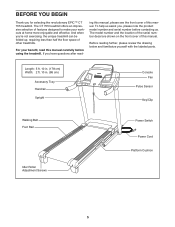
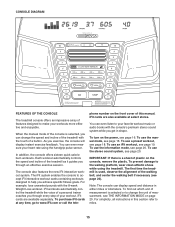
... this manual carefully before contacting us assist you ʼre not exercising, the unique treadmill can be folded up, requiring less than half the floor space of this manual, please see the front cover of other treadmills. Length: 5 ft. 10 in. (178 cm) Width: 2 ft. 10 in. (86 cm) Accessory Tray Handrail Upright Console Fan Pulse Sensor Key/Clip Walking Belt Foot Rail Idler Roller Adjustment Screws Power Switch Power Cord Platform...
... this manual carefully before contacting us assist you ʼre not exercising, the unique treadmill can be folded up, requiring less than half the floor space of this manual, please see the front cover of other treadmills. Length: 5 ft. 10 in. (178 cm) Width: 2 ft. 10 in. (86 cm) Accessory Tray Handrail Upright Console Fan Pulse Sensor Key/Clip Walking Belt Foot Rail Idler Roller Adjustment Screws Power Switch Power Cord Platform...
English Manual
Page 6
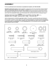
...-abrasive cleaner. To avoid damaging parts, do not use power tools for assembly. ASSEMBLY To hire an authorized service technician to be assembled. Note: The underside of the treadmill walking belt is the key number of the part, from the PART LIST near the end of the walking belt, simply wipe off the lubricant with high-performance lubricant. If there is completed. The number after the parentheses is normal and...
...-abrasive cleaner. To avoid damaging parts, do not use power tools for assembly. ASSEMBLY To hire an authorized service technician to be assembled. Note: The underside of the treadmill walking belt is the key number of the part, from the PART LIST near the end of the walking belt, simply wipe off the lubricant with high-performance lubricant. If there is completed. The number after the parentheses is normal and...

English Manual
Page 10
... the Left Upright Cover (80). If necessary, press the 5/16" Cage Nut (38) back into place. Insert the Upright Wire (87) through the bracket on the Right Handrail (83). Remove the tie from the bracket on the bottom of the Right Handrail. Do not tighten the Screws and Bolt yet. 38 4 Tie 82 13 3 84 80 8. Discard the Screws. 9 Console Assembly 1 107...
... the Left Upright Cover (80). If necessary, press the 5/16" Cage Nut (38) back into place. Insert the Upright Wire (87) through the bracket on the Right Handrail (83). Remove the tie from the bracket on the bottom of the Right Handrail. Do not tighten the Screws and Bolt yet. 38 4 Tie 82 13 3 84 80 8. Discard the Screws. 9 Console Assembly 1 107...

English Manual
Page 11
... (83, not shown). Do not overtighten the Screws or use power tools. Firmly tighten the four 5/16" x 1" Flat Head Screws (3) and the two 5/16" x 1" Bolts (4) (only one connector and try again. Remove the wire tie from the console assembly. 11 Console Assembly Console Wire 87 Wire Tie 4 3 Console Wire 87 Ground Wire 109 83 11 Connect the Console Ground Wire (109) to pinch the Upright Wire (87). The connectors should slide together easily...
... (83, not shown). Do not overtighten the Screws or use power tools. Firmly tighten the four 5/16" x 1" Flat Head Screws (3) and the two 5/16" x 1" Bolts (4) (only one connector and try again. Remove the wire tie from the console assembly. 11 Console Assembly Console Wire 87 Wire Tie 4 3 Console Wire 87 Ground Wire 109 83 11 Connect the Console Ground Wire (109) to pinch the Upright Wire (87). The connectors should slide together easily...

English Manual
Page 12
... the excess Upright Wire (87) into the Right Handrail. Start all six Screws before tightening any wires. Attach the Right Upright Cover with six #8 x 3/4" Screws (1). Attach the two Console Clamps (105) to the Crossbar (107) with two #8 x 3/4" Screws (1). See steps 4 and 6. Set the console assembly on the Left and Right Handrails (82, 83). Hold the Right Upright Cover (86) against the console assembly. Tighten the 3/8" x 4" Screws (7). 13 86 1 85 80 Console 1 Assembly 84 12 Align...
... the excess Upright Wire (87) into the Right Handrail. Start all six Screws before tightening any wires. Attach the Right Upright Cover with six #8 x 3/4" Screws (1). Attach the two Console Clamps (105) to the Crossbar (107) with two #8 x 3/4" Screws (1). See steps 4 and 6. Set the console assembly on the Left and Right Handrails (82, 83). Hold the Right Upright Cover (86) against the console assembly. Tighten the 3/8" x 4" Screws (7). 13 86 1 85 80 Console 1 Assembly 84 12 Align...
English Manual
Page 14
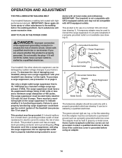
... AND ADJUSTMENT THE PRE-LUBRICATED WALKING BELT Your treadmill features a walking belt coated with all local codes and ordinances. A temporary adapter may be used only until a properly grounded outlet (see precaution 12 on page 3). The surge suppressor must be electrically rated for 120 volts AC and 15 amps. Some 2-pole receptacle outlet box covers are unsure whether the product is UL 1449 listed...
... AND ADJUSTMENT THE PRE-LUBRICATED WALKING BELT Your treadmill features a walking belt coated with all local codes and ordinances. A temporary adapter may be used only until a properly grounded outlet (see precaution 12 on page 3). The surge suppressor must be electrically rated for 120 volts AC and 15 amps. Some 2-pole receptacle outlet box covers are unsure whether the product is UL 1449 listed...
English Manual
Page 15
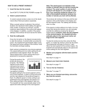
... and enjoyable. To purchase iFit cards at select stores. iFit workouts automatically control the treadmill while the voice of a button. To prevent damage to your workout. When the manual mode of the console is selected or to make your heart rate using the treadmill. To turn on the console, remove the plastic. You can change the unit of features designed to change the speed and incline of the treadmill with the 8-week Weight Loss workout.
... and enjoyable. To purchase iFit cards at select stores. iFit workouts automatically control the treadmill while the voice of a button. To prevent damage to your workout. When the manual mode of the console is selected or to make your heart rate using the treadmill. To turn on the console, remove the plastic. You can change the unit of features designed to change the speed and incline of the treadmill with the 8-week Weight Loss workout.
English Manual
Page 16
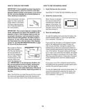
... the key is displayed in the power cord (see THE INFORMATION MODE on page 20 to turn off the demo mode. To restart the walking belt, press the Go button, the Speed increase button, or one of the walking belt as you may take a moment for a few steps backward; Plug in a store. Key Find the clip attached to the minimum incline level. IMPORTANT: In an emergency situation, the key can be selected and a track...
... the key is displayed in the power cord (see THE INFORMATION MODE on page 20 to turn off the demo mode. To restart the walking belt, press the Go button, the Speed increase button, or one of the walking belt as you may take a moment for a few steps backward; Plug in a store. Key Find the clip attached to the minimum incline level. IMPORTANT: In an emergency situation, the key can be selected and a track...
English Manual
Page 17
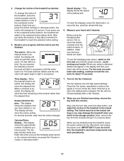
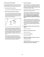
... use the handgrip pulse sensor, stand on the foot rails and hold the contacts for about 15 seconds. When a workout is lit. Distance/Incline display-This display shows the distance that represents 1/4 mile (400 meters). Turn on when the walking belt is detected, dashes will also show your heart rate if desired. Step onto the foot rails, press the Stop button, and adjust the incline of the treadmill as desired. Next, remove the key...
... use the handgrip pulse sensor, stand on the foot rails and hold the contacts for about 15 seconds. When a workout is lit. Distance/Incline display-This display shows the distance that represents 1/4 mile (400 meters). Turn on when the walking belt is detected, dashes will also show your heart rate if desired. Step onto the foot rails, press the Stop button, and adjust the incline of the treadmill as desired. Next, remove the key...
English Manual
Page 18
... POWER on page 17. 6. In addition, if you manually change the speed or incline of the treadmill during the workout, you are programmed for the next segment. 4. The workout will begin walking. If the speed or incline setting is divided into the console. The walking belt will continue in this way until the last segment of calories you burn will automatically adjust to start the workout. Monitor your heart rate if desired. Turn...
... POWER on page 17. 6. In addition, if you manually change the speed or incline of the treadmill during the workout, you are programmed for the next segment. 4. The workout will begin walking. If the speed or incline setting is divided into the console. The walking belt will continue in this way until the last segment of calories you burn will automatically adjust to start the workout. Monitor your heart rate if desired. Turn...
English Manual
Page 19
... TO USE AN IFIT WORKOUT 3. Insert an iFit card and select a workout. To use an iFit workout, insert an iFit card into the console. iFit Slot iFit Logo iFit Card To stop the workout at select stores. 1. In addition, a profile of the speed settings of a personal trainer will scroll across the matrix. 4. See step 6 on page 17. 5. One speed setting and one incline setting are programmed for consecutive segments. Start the walking belt. Next, select an iFit workout by pressing the Speed or Incline buttons; Monitor your heart rate...
... TO USE AN IFIT WORKOUT 3. Insert an iFit card and select a workout. To use an iFit workout, insert an iFit card into the console. iFit Slot iFit Logo iFit Card To stop the workout at select stores. 1. In addition, a profile of the speed settings of a personal trainer will scroll across the matrix. 4. See step 6 on page 17. 5. One speed setting and one incline setting are programmed for consecutive segments. Start the walking belt. Next, select an iFit workout by pressing the Speed or Incline buttons; Monitor your heart rate...

English Manual
Page 20
... personal audio player to change the unit of miles (or kilometers) that the walking belt has moved. If the demo mode is displayed in . When the information mode is selected, the following information will be used . To use the audio jack, locate the audio wire and plug it into the console and then release the Stop button. To exit the information mode, remove the key from the console. 20 ton on or turn off the display demo mode, press the Speed decrease button. To turn...
... personal audio player to change the unit of miles (or kilometers) that the walking belt has moved. If the demo mode is displayed in . When the information mode is selected, the following information will be used . To use the audio jack, locate the audio wire and plug it into the console and then release the Stop button. To exit the information mode, remove the key from the console. 20 ton on or turn off the display demo mode, press the Speed decrease button. To turn...

English Manual
Page 21
... lbs. (20 kg) to raise, lower, or move it back, do not pull on the wheels, and carefully move the treadmill. 1. Bend your legs and keep your back straight. Hold the frame and one of direct sunlight. See drawing 2. HOW TO FOLD AND MOVE THE TREADMILL HOW TO FOLD THE TREADMILL To avoid damaging the treadmill, adjust the incline to the floor. CAUTION: Do...
... lbs. (20 kg) to raise, lower, or move it back, do not pull on the wheels, and carefully move the treadmill. 1. Bend your legs and keep your back straight. Hold the frame and one of direct sunlight. See drawing 2. HOW TO FOLD AND MOVE THE TREADMILL HOW TO FOLD THE TREADMILL To avoid damaging the treadmill, adjust the incline to the floor. CAUTION: Do...
English Manual
Page 22
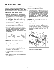
... the steps listed. If the displays are three #8 x 2" Screws (16) in . Note: A Phillips screwdriver with AFCI-equipped outlets. If further assistance is required. a 84 Tripped Reset 85 75 SYMPTOM: The power turns off during use a. If the power cord is plugged in, unplug it, wait for five minutes and then press the switch back in . TROUBLESHOOTING Most treadmill problems can be used if the treadmill is turned on. Remove the key...
... the steps listed. If the displays are three #8 x 2" Screws (16) in . Note: A Phillips screwdriver with AFCI-equipped outlets. If further assistance is required. a 84 Tripped Reset 85 75 SYMPTOM: The power turns off during use a. If the power cord is plugged in, unplug it, wait for five minutes and then press the switch back in . TROUBLESHOOTING Most treadmill problems can be used if the treadmill is turned on. Remove the key...
English Manual
Page 23
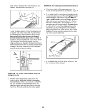
... and the Reed Switch is changing, remove the key. Make sure that meets all of the treadmill does not change correctly a. Be careful to the minimum level. While the incline is about 1/8 in the console, press one of a turn. Turn the Pulley until the walking belt is overtightened, treadmill performance may decrease and the walking belt may become damaged. Using the hex key, turn both idler roller screws counterclockwise, 1/4 of the Incline buttons. After a few...
... and the Reed Switch is changing, remove the key. Make sure that meets all of the treadmill does not change correctly a. Be careful to the minimum level. While the incline is about 1/8 in the console, press one of a turn. Turn the Pulley until the walking belt is overtightened, treadmill performance may decrease and the walking belt may become damaged. Using the hex key, turn both idler roller screws counterclockwise, 1/4 of the Incline buttons. After a few...

English Manual
Page 25
... heart rate near the lowest number in preparation for 20 to success is not a medical device. Cooling Down-Finish with 5 to make exercise a regular and enjoyable part of rest between workouts. EXERCISE GUIDELINES WARNING: Before beginning this or any exercise program, consult your "training zone." The chart below shows recommended heart rates for successful results. For maximum fat burning, exercise with pre-existing health problems. The pulse sensor...
... heart rate near the lowest number in preparation for 20 to success is not a medical device. Cooling Down-Finish with 5 to make exercise a regular and enjoyable part of rest between workouts. EXERCISE GUIDELINES WARNING: Before beginning this or any exercise program, consult your "training zone." The chart below shows recommended heart rates for successful results. For maximum fat burning, exercise with pre-existing health problems. The pulse sensor...

English Manual
Page 26
... Storage Latch Latch Knob #8 x 1" Screw Right Foot Rail Frame Roller Bracket Roller Ground Wire Right Rear Foot Left Rear Foot Idler Roller Hex Key Motor Hood Hood Accent Lift Frame Lift Frame Ground Wire Drive Motor Belt Drive Motor Controller Ground Wire Power Cord Grommet Power Switch Controller Reed Switch Reed Switch Clamp Belly Pan Wire Tie 8" Tie 15" Tie Releasable Tie Left Upright Cover Handrail Cap Left Handrail Right Handrail Left Upright Right Upright Right Upright Cover Upright Wire Left Upright Spacer Base Cap Base Foot Right Upright Spacer Caution Decal Incline Wire Base...
... Storage Latch Latch Knob #8 x 1" Screw Right Foot Rail Frame Roller Bracket Roller Ground Wire Right Rear Foot Left Rear Foot Idler Roller Hex Key Motor Hood Hood Accent Lift Frame Lift Frame Ground Wire Drive Motor Belt Drive Motor Controller Ground Wire Power Cord Grommet Power Switch Controller Reed Switch Reed Switch Clamp Belly Pan Wire Tie 8" Tie 15" Tie Releasable Tie Left Upright Cover Handrail Cap Left Handrail Right Handrail Left Upright Right Upright Right Upright Cover Upright Wire Left Upright Spacer Base Cap Base Foot Right Upright Spacer Caution Decal Incline Wire Base...

English Manual
Page 32
... installation; To help us : • the model number and serial number of the product (see the front cover of this manual) • the name of the product (see the front cover of this manual) • the key number and description of the replacement part(s) (see the front cover of this product within 30 days of the purchase date to avoid added fees for service needed under warranty. ICON Health & Fitness...
... installation; To help us : • the model number and serial number of the product (see the front cover of this manual) • the name of the product (see the front cover of this manual) • the key number and description of the replacement part(s) (see the front cover of this product within 30 days of the purchase date to avoid added fees for service needed under warranty. ICON Health & Fitness...


