

English Manual
Page 1
EPTL69011.1 Serial No. MT Sat. 8 a.m.-4 p.m. If you have questions, or if parts are damaged or missing, DO NOT CONTACT THE STORE; IMPORTANT: Please register this product (see the limited warranty on the back cover of this manual) before using this equipment. MT ON THE WEB: www.iconservice.com CAUTION Read all precautions and instructions in the space above for future reference. please contact Customer Care. Save this manual before contacting Customer Care. www.iconfitness.com Model No. CALL TOLL-FREE: 1-866-997-6999 Mon.-Fri. 6 a.m.-6 p.m. Write the serial number in ...
EPTL69011.1 Serial No. MT Sat. 8 a.m.-4 p.m. If you have questions, or if parts are damaged or missing, DO NOT CONTACT THE STORE; IMPORTANT: Please register this product (see the limited warranty on the back cover of this manual) before using this equipment. MT ON THE WEB: www.iconservice.com CAUTION Read all precautions and instructions in the space above for future reference. please contact Customer Care. Save this manual before contacting Customer Care. www.iconfitness.com Model No. CALL TOLL-FREE: 1-866-997-6999 Mon.-Fri. 6 a.m.-6 p.m. Write the serial number in ...

English Manual
Page 2
Apply the decal in the location shown. If a decal is missing or illegible, call the telephone number on the front cover of the warning decals. Note: The decals may not be shown at actual size. 2 TABLE OF CONTENTS WARNING DECAL PLACEMENT 2 IMPORTANT PRECAUTIONS 3 BEFORE YOU BEGIN 5 ASSEMBLY 6 OPERATION AND ADJUSTMENT 14 HOW TO FOLD AND MOVE THE TREADMILL 21 TROUBLESHOOTING 22 EXERCISE GUIDELINES 25 PART LIST 26 EXPLODED DRAWING 28 ORDERING REPLACEMENT PARTS Back Cover LIMITED WARRANTY Back Cover WARNING DECAL PLACEMENT This drawing shows the locations of this manual and ...
Apply the decal in the location shown. If a decal is missing or illegible, call the telephone number on the front cover of the warning decals. Note: The decals may not be shown at actual size. 2 TABLE OF CONTENTS WARNING DECAL PLACEMENT 2 IMPORTANT PRECAUTIONS 3 BEFORE YOU BEGIN 5 ASSEMBLY 6 OPERATION AND ADJUSTMENT 14 HOW TO FOLD AND MOVE THE TREADMILL 21 TROUBLESHOOTING 22 EXERCISE GUIDELINES 25 PART LIST 26 EXPLODED DRAWING 28 ORDERING REPLACEMENT PARTS Back Cover LIMITED WARRANTY Back Cover WARNING DECAL PLACEMENT This drawing shows the locations of this manual and ...

English Manual
Page 3
... sustained by persons weighing 300 lbs. (136 kg) or less. 9. Before beginning any surface that meets all warnings on your treadmill before using your local EPIC dealer or call the telephone number on each side. This is the responsibility of the owner to the control system of the specifications described on...
... sustained by persons weighing 300 lbs. (136 kg) or less. 9. Before beginning any surface that meets all warnings on your treadmill before using your local EPIC dealer or call the telephone number on each side. This is the responsibility of the owner to the control system of the specifications described on...
English Manual
Page 4
20. Never leave the treadmill unattended while it is properly assembled. (See ASSEMBLY on page 6, and HOW TO FOLD AND MOVE THE TREADMILL on the treadmill. 24. less instructed to raise, lower, or move the treadmill until it is intended for the location of the treadmill regularly. vice representative. Inspect and properly tighten all parts of the power switch.) 21. DANGER: 25. nance and adjustment procedures described in serious injury or death. Never remove the motor hood un- Over exercising may result in this manual should be able to safely lift 45 lbs. (20 kg) to do...
20. Never leave the treadmill unattended while it is properly assembled. (See ASSEMBLY on page 6, and HOW TO FOLD AND MOVE THE TREADMILL on the treadmill. 24. less instructed to raise, lower, or move the treadmill until it is intended for the location of the treadmill regularly. vice representative. Inspect and properly tighten all parts of the power switch.) 21. DANGER: 25. nance and adjustment procedures described in serious injury or death. Never remove the motor hood un- Over exercising may result in this manual should be able to safely lift 45 lbs. (20 kg) to do...
English Manual
Page 5
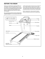
... not exercising, the unique treadmill can be folded up, requiring less than half the floor space of other treadmills. If you for selecting the revolutionary EPIC™ CT 705 treadmill.
... not exercising, the unique treadmill can be folded up, requiring less than half the floor space of other treadmills. If you for selecting the revolutionary EPIC™ CT 705 treadmill.
English Manual
Page 6
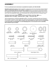
The number after the parentheses is the quantity needed for assembly. Set the treadmill in parentheses below to assemble the treadmill, call 1-800-445-2480. The number in a cleared area and remove all packing materials. If there is the key number of the part, from the PART LIST near the end of the walking belt or the shipping carton. Note: If a part is not in the hardware kit, check to see if it is coated with a soft cloth and a mild, non-abrasive cleaner. Note: The underside of the treadmill walking belt is preattached to one of the parts to be transferred to ...
The number after the parentheses is the quantity needed for assembly. Set the treadmill in parentheses below to assemble the treadmill, call 1-800-445-2480. The number in a cleared area and remove all packing materials. If there is the key number of the part, from the PART LIST near the end of the walking belt or the shipping carton. Note: If a part is not in the hardware kit, check to see if it is coated with a soft cloth and a mild, non-abrasive cleaner. Note: The underside of the treadmill walking belt is preattached to one of the parts to be transferred to ...

English Manual
Page 7
Cut the shipping tie securing the Upright Wire (87) to the Base (95) with a 3/8" x 2" Bolt (8) and a 3/8" Nut (10). Then, attach the other two Base Feet (90) with two #8 x 1" Tek Screws (5) and two Base Foot Spacers (94). See the inset drawing. Do not overtighten the Nut; Partially fold the Frame (55) so that the power cord is more stable; Locate a plastic tie in the indicated hole in the locations shown with two #8 x 1" Tek Screws (5). Hole 87 94 55 90 5 2. the Wheel must turn freely. do not fully fold the Frame yet. Attach two Base Feet (90) to the Base (95)...
Cut the shipping tie securing the Upright Wire (87) to the Base (95) with a 3/8" x 2" Bolt (8) and a 3/8" Nut (10). Then, attach the other two Base Feet (90) with two #8 x 1" Tek Screws (5) and two Base Foot Spacers (94). See the inset drawing. Do not overtighten the Nut; Partially fold the Frame (55) so that the power cord is more stable; Locate a plastic tie in the indicated hole in the locations shown with two #8 x 1" Tek Screws (5). Hole 87 94 55 90 5 2. the Wheel must turn freely. do not fully fold the Frame yet. Attach two Base Feet (90) to the Base (95)...

English Manual
Page 8
If necessary, turn the Right Upright Spacer and try again. Insert a 3/8" x 4" 4 Screw (7) with "Right" stickers. Hold the Right Upright (85) against the Base. Set the Right Upright Spacer on the Base (95). Have a second person hold the Right Upright (85) near the Base (95). Hold a Screw Spacer (14) inside the lower end of the Upright Wire (87). Insert the Upright Wire (87) through the Right Upright. 3 87 A 87 B 91 Wire Tie 85 Wire Tie C 95 91 85 87 91 95 95 Correct 4. See inset drawings B and C. Then, pull the other end of the wire tie until the heads of the ...
If necessary, turn the Right Upright Spacer and try again. Insert a 3/8" x 4" 4 Screw (7) with "Right" stickers. Hold the Right Upright (85) against the Base. Set the Right Upright Spacer on the Base (95). Have a second person hold the Right Upright (85) near the Base (95). Hold a Screw Spacer (14) inside the lower end of the Upright Wire (87). Insert the Upright Wire (87) through the Right Upright. 3 87 A 87 B 91 Wire Tie 85 Wire Tie C 95 91 85 87 91 95 95 Correct 4. See inset drawings B and C. Then, pull the other end of the wire tie until the heads of the ...

English Manual
Page 9
do not fully tighten the Screws yet. Press a Base Cap (89) into the Left Upright and the Screw Spacer. If necessary, turn freely. do not fully fold the Frame yet. Partially fold the Frame (55) so that the Left Upright Spacer sits flush against the Base (95). Make sure that the treadmill is flat on the floor. 9 With the help of a second person, tip the treadmill so that the Base (95) is more stable; Insert a 3/8" x 4" Screw 6 (7) with a second Screw Spacer (14), 3/8" x 84 4" Screw (7), and 3/8" Star Washer (11). Repeat this 7 step with a 3/8" Star Washer (11...
do not fully tighten the Screws yet. Press a Base Cap (89) into the Left Upright and the Screw Spacer. If necessary, turn freely. do not fully fold the Frame yet. Partially fold the Frame (55) so that the Left Upright Spacer sits flush against the Base (95). Make sure that the treadmill is flat on the floor. 9 With the help of a second person, tip the treadmill so that the Base (95) is more stable; Insert a 3/8" x 4" Screw 6 (7) with a second Screw Spacer (14), 3/8" x 84 4" Screw (7), and 3/8" Star Washer (11). Repeat this 7 step with a 3/8" Star Washer (11...

English Manual
Page 10
If necessary, press the 5/16" Cage Nut (38) back into place. Do not tighten the Screws and Bolt yet. 38 4 Tie 82 13 3 84 80 8. If necessary, press the 5/16" Cage Nut (38) back into place. Attach the Right Handrail (83) to the Right Upright (85) with two 5/16" x 1" Flat Head Screws (3) and a 5/16" x 1" Bolt (4) with a 5/16" Star Washer (13). Remove the tie from the bracket on a soft surface to the Left Upright (84) with two 5/16" x 1" Flat Head Screws (3) and a 5/16" x 1" Bolt (4) with a 5/16" Star Washer (13). Insert the Upright Wire (87) through the bracket on the ...
If necessary, press the 5/16" Cage Nut (38) back into place. Do not tighten the Screws and Bolt yet. 38 4 Tie 82 13 3 84 80 8. If necessary, press the 5/16" Cage Nut (38) back into place. Attach the Right Handrail (83) to the Right Upright (85) with two 5/16" x 1" Flat Head Screws (3) and a 5/16" x 1" Bolt (4) with a 5/16" Star Washer (13). Remove the tie from the bracket on a soft surface to the Left Upright (84) with two 5/16" x 1" Flat Head Screws (3) and a 5/16" x 1" Bolt (4) with a 5/16" Star Washer (13). Insert the Upright Wire (87) through the bracket on the ...

English Manual
Page 11
Next, tighten the four 1/4" x 1" Screws (9). 10 First 29 12 82 102 107 First 29 12 87 83 11. Connect the Upright Wire (87) to pinch the Upright Wire (87). The connectors should slide together easily and snap into the Handrails (82, 83). If they do not, turn one side is shown). Do not tighten the Screws yet. Be careful not to the console wire. Do not overtighten the Screws or use power tools. Tighten the two indicated #10 x 3/4"Screws (2) first. IF THE CONNECTORS ARE NOT CONNECTED PROPERLY, THE CONSOLE MAY BE DAMAGED WHEN YOU TURN ON THE POWER. Insert the Console ...
Next, tighten the four 1/4" x 1" Screws (9). 10 First 29 12 82 102 107 First 29 12 87 83 11. Connect the Upright Wire (87) to pinch the Upright Wire (87). The connectors should slide together easily and snap into the Handrails (82, 83). If they do not, turn one side is shown). Do not tighten the Screws yet. Be careful not to the console wire. Do not overtighten the Screws or use power tools. Tighten the two indicated #10 x 3/4"Screws (2) first. IF THE CONNECTORS ARE NOT CONNECTED PROPERLY, THE CONSOLE MAY BE DAMAGED WHEN YOU TURN ON THE POWER. Insert the Console ...

English Manual
Page 12
12. Set the console assembly on the Left and Right Handrails (82, 83). Align the holes in the Right Upright Cover with two #8 x 3/4" Screws (1). Attach the two Console Clamps (105) to the Left Upright (84) in the Right Upright (85). See steps 4 and 6. Attach the Left Upright Cover (80) to the console assembly with six #8 x 3/4" Screws (1). Be careful not to the Crossbar (107) with four #8 x 1" Screws (53). 12 87 Console Assembly 105 53 107 83 1 1 1 82 1 13. Attach the console assembly to pinch any of them. Attach the Right Upright Cover with the holes in the ...
12. Set the console assembly on the Left and Right Handrails (82, 83). Align the holes in the Right Upright Cover with two #8 x 3/4" Screws (1). Attach the two Console Clamps (105) to the Left Upright (84) in the Right Upright (85). See steps 4 and 6. Attach the Left Upright Cover (80) to the console assembly with six #8 x 3/4" Screws (1). Be careful not to the Crossbar (107) with four #8 x 1" Screws (53). 12 87 Console Assembly 105 53 107 83 1 1 1 82 1 13. Attach the console assembly to pinch any of them. Attach the Right Upright Cover with the holes in the ...

English Manual
Page 13
Have a second person hold the Frame until this step is used to adjust the walking belt (see HOW TO LOWER THE TREADMILL FOR USE on page 21). 15 55 10 8 51 52 Large Barrel 95 6 16. Attach the lower end of the Storage Latch (51) to align the Storage Latch with the Base. Note: Extra hardware may be included. Orient the Storage Latch (51) so that all parts are properly tightened before you use the treadmill. Note: It may be necessary to move the Frame (55) back and forth to the Base (95) with a 3/8" x 2" Bolt (8) and a 3/8" Nut (10). Keep the included hex key in a ...
Have a second person hold the Frame until this step is used to adjust the walking belt (see HOW TO LOWER THE TREADMILL FOR USE on page 21). 15 55 10 8 51 52 Large Barrel 95 6 16. Attach the lower end of the Storage Latch (51) to align the Storage Latch with the Base. Note: Extra hardware may be included. Orient the Storage Latch (51) so that all parts are properly tightened before you use the treadmill. Note: It may be necessary to move the Frame (55) back and forth to the Base (95) with a 3/8" x 2" Bolt (8) and a 3/8" Nut (10). Keep the included hex key in a ...
English Manual
Page 14
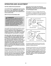
... with all local codes and ordinances. IMPORTANT: Never apply silicone spray or other electronic equipment, can be damaged by a metal screw. Such substances will not fit the outlet, have a UL-suppressed voltage rating of 400 volts or less and a minimum surge dissipation of damaging your treadmill (see precaution 12 on page...
... with all local codes and ordinances. IMPORTANT: Never apply silicone spray or other electronic equipment, can be damaged by a metal screw. Such substances will not fit the outlet, have a UL-suppressed voltage rating of 400 volts or less and a minimum surge dissipation of damaging your treadmill (see precaution 12 on page...
English Manual
Page 15
... of this section refer to help you through an effective exercise session. To turn on the front cover of a personal trainer coaches you achieve specific fitness goals. To use an iFit workout, see page 16. To use a preset workout, see page 20. The iFit system enables the console to accept iFit...
... of this section refer to help you through an effective exercise session. To turn on the front cover of a personal trainer coaches you achieve specific fitness goals. To use an iFit workout, see page 16. To use a preset workout, see page 20. The iFit system enables the console to accept iFit...
English Manual
Page 16
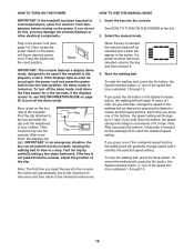
Next, locate the power switch on the power. Test the clip by 0.1 mph; When the key is not pulled from the console, causing the walking belt to slow to the key and slide the clip onto the waistband of your clothes. If you may take a moment for a few steps backward; If you do not do this, you press one of the numbered speed buttons, the walking belt will gradually change the speed of the speed buttons numbered 1 through 10. Select the manual mode. Press the switch into the console. After a mo- if the key is inserted, the manual mode will be ...
Next, locate the power switch on the power. Test the clip by 0.1 mph; When the key is not pulled from the console, causing the walking belt to slow to the key and slide the clip onto the waistband of your clothes. If you may take a moment for a few steps backward; If you do not do this, you press one of the numbered speed buttons, the walking belt will gradually change the speed of the speed buttons numbered 1 through 10. Select the manual mode. Press the switch into the console. After a mo- if the key is inserted, the manual mode will be ...
English Manual
Page 17
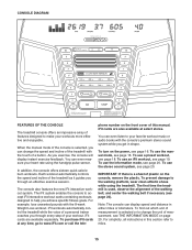
Note: After you press the buttons, it may take a moment for the treadmill to turn off automatically after a few minutes. 8. Measure your progress with the matrix and the displays. Contacts To use the handgrip pulse sensor or the volume level when you have walked or run. Time display-When the manual mode is selected, the display will change the incline of the treadmill, press the Incline increase and decrease buttons or one of the numbered incline buttons, the treadmill will also show the incline setting for about 15 seconds. Turn on when the walking belt is detected, ...
Note: After you press the buttons, it may take a moment for the treadmill to turn off automatically after a few minutes. 8. Measure your progress with the matrix and the displays. Contacts To use the handgrip pulse sensor or the volume level when you have walked or run. Time display-When the manual mode is selected, the display will change the incline of the treadmill, press the Incline increase and decrease buttons or one of the numbered incline buttons, the treadmill will also show the incline setting for about 15 seconds. Turn on when the walking belt is detected, ...
English Manual
Page 18
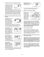
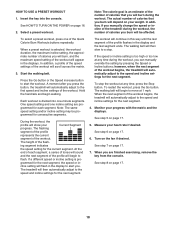
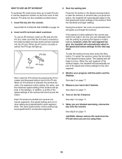
HOW TO USE A PRESET WORKOUT 1. When a preset workout is selected, the workout duration, the maximum incline setting, the approximate number of calories you burn will appear in the displays. The flashing segment of the profile represents the current segment of the workout will be programmed for consecutive segments. ing segment indicates the speed setting for the next segment. The workout will burn, and the maximum speed setting of the workout. In addition, if you manually change the speed or incline of the treadmill during the workout, the number of ...
HOW TO USE A PRESET WORKOUT 1. When a preset workout is selected, the workout duration, the maximum incline setting, the approximate number of calories you burn will appear in the displays. The flashing segment of the profile represents the current segment of the workout will be programmed for consecutive segments. ing segment indicates the speed setting for the next segment. The workout will burn, and the maximum speed setting of the workout. In addition, if you manually change the speed or incline of the treadmill during the workout, the number of ...
English Manual
Page 19
Insert an iFit card and select a workout. When the next segment of the workout. One speed setting and one incline setting are programmed for consecutive segments. HOW TO USE AN IFIT WORKOUT 3. Insert the key into the iFit slot; A moment after you press the button, the treadmill will automatically adjust to the first speed and incline settings of the workout begins, the treadmill will automatically adjust to the speed and incline settings for the next segment. iFit Slot iFit Logo iFit Card To stop the workout at any time, go to move. In addition, a profile...
Insert an iFit card and select a workout. When the next segment of the workout. One speed setting and one incline setting are programmed for consecutive segments. HOW TO USE AN IFIT WORKOUT 3. Insert the key into the iFit slot; A moment after you press the button, the treadmill will automatically adjust to the first speed and incline settings of the workout begins, the treadmill will automatically adjust to the speed and incline settings for the next segment. iFit Slot iFit Logo iFit Card To stop the workout at any time, go to move. In addition, a profile...

English Manual
Page 20
When the information mode is selected, the following information will be shown: The Time display will function normally when you plug in the power cord, press the power switch into the reset position, and insert the key into a jack on your MP3 player, CD player, or other personal audio player to be used if the treadmill is displayed in the Speed display while the information mode is selected. The Distance/Incline display will appear in . Next, press the Play but- While the demo mode is turned on, the console will show the total number of miles (or kilometers) that the audio wire...
When the information mode is selected, the following information will be shown: The Time display will function normally when you plug in the power cord, press the power switch into the reset position, and insert the key into a jack on your MP3 player, CD player, or other personal audio player to be used if the treadmill is displayed in the Speed display while the information mode is selected. The Distance/Incline display will appear in . Next, press the Play but- While the demo mode is turned on, the console will show the total number of miles (or kilometers) that the audio wire...