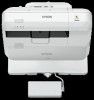
Installation Guide - Control Pad and Touch Unit
Page 3
...laser could possibly result in personal injury or even death due to incorrect handling. Incorrect handling that should be strong enough to hold the projector, the wall mount, as well as the Control Pad and the Touch Unit, if necessary. Keep this guide: • BrightLink® 695Wi/695Wi+/696Ui/697Ui • BrightLink Pro... and BrightLink Pro 1450Ui/1460Ui. The Control Pad should be connected to these warnings when reading this guide to install and operate the Touch Unit. Safety Instructions For your Epson® projector. This symbol indicates related or useful information...
Installation Guide - Control Pad and Touch Unit
Page 4
... to any direction on the screen surface. 0.2 in. (5 mm) 3 Connect the Touch Unit to malfunction. Do not view the laser light using or near medical equipment such as a pacemaker. English Warning Do not apply optical devices such as a magnifying glass or telescope to... a magnifying glass within the Touch Unit generates electromagnetic interference which could corrupt data or cause the media or device to BrightLink 695Wi/695Wi+/696Ui/697Ui and BrightLink Pro 1450Wi/1460Ui models only. The magnet within a range of the following conditions: • The Touch Unit can be ...
Installation Guide - Control Pad and Touch Unit
Page 8
...Port protection stickers 8.3 in. (210 mm) 2.0 in . (95 mm) English Control Pad (BrightLink 697Ui and BrightLink Pro 1450Ui/1460Ui) The following information: • Invisible laser radiation • Do not view the beam directly with your projector and are packaged with optical instruments ...• Class 1 laser product 7 Control Pad Pen stand 2 Specifications Stereo mini connection...
Installation Guide - Control Pad and Touch Unit
Page 9
Laser diffusion port The laser beam is diffused from the laser diffusion ports on the back of the Touch Unit. Control Pad External dimensions and weight The Control Pad weighs approximately 8.2 ounces (262 g). 5.4 in (135.9 mm) 0.4 in (11.5 mm) 4.4 in (111 mm) 4.3 in (109 mm) 0.1 in (3.5 mm) 2.5 in (63.3 mm) 4.2 in (107 mm) 1.9 in (47 mm) 6.0 in (153.5 mm) 0.6 in (15.47 mm) 2.0 in (51.5 mm) 1.1 in (29 mm) 1.2 in (30.9 mm) 8
Installation Guide - Control Pad and Touch Unit
Page 18
... for detailed instructions on the Touch Unit. Refer to calibrate the interactive pen(s) before adjusting the angle. G Adjust the angle Adjust the angle of the laser light coming from the Extended menu. 17
Installation Guide - Control Pad and Touch Unit
Page 19
Warning Do not look into the projector's projection window or the Touch Unit's laser diffusion ports (located on and the indicator light turns blue. Select Touch Unit Setup. 3. When Power is turned on. 4. Select Angle Adjustment. 18 Select Power and set to On, the Touch Unit automatically powers up the next time the projector is set to On. The Touch Unit power turns on the back of the Touch Unit); this could cause injury to eyesight. 2.
Installation Guide - Control Pad and Touch Unit
Page 27
After placing the infrared deflectors, press the or button on them. If the dots do not disappear even after performing the above procedures, contact Epson. 18. Perform touch calibration by the obstacle. H Attach cover Attach the dial cover. 17. Select Touch Calibration and follow the instructions. Make sure to match ... removed, such as necessary to tighten the screw at the bottom of the supplied infrared deflectors and stick them to the screen so that the laser is placed on the remote control, and then repeat step 12.
Installation Guide - Control Pad and Touch Unit
Page 32
... port on calibrating the pen(s). 1. English F Connect the cable Connect the Touch Unit connection cable that the Touch Unit can detect the position of the laser light coming from the Extended menu. 31 Select Easy Interactive Function from the Touch Unit so that is connected to the projector to the projector...
Installation Guide - Control Pad and Touch Unit
Page 33
this could cause injury to On. Select Power and set to On, the Touch Unit automatically powers up the next time the projector is set to eyesight. When Power is turned on. 4. The Touch Unit power turns on the back of the Touch Unit); Select Angle Adjustment. 32 Warning Do not look into the projector's projection window or the Touch Unit's laser diffusion ports (located on and the indicator light turns blue. Select Touch Unit Setup. 3. 2.
Installation Guide - Control Pad and Touch Unit
Page 39
... frames, go to step 15. Select Touch Calibration and follow the instructions. • If the dots still remain or there are obstacles that the laser is placed on the remote control and then go to step 14. 14. Make sure to stick the deflectors between the dots and the obstacle... deflectors as necessary to the screen so that cannot be removed, such as shown below), do not disappear even after performing the above procedures, contact Epson. 15. If the dots do the following: • Remove any obstacles from the back of the supplied infrared deflectors and stick them to match...
Installation Guide - All-in-One Whiteboard and Mount System AN3WA100
Page 2
... in this mounting system outdoors. Milestone assumes no responsibility for every possible contingency in connection with the following Epson projector models: Lamp-Style • BrightLink Pro 1450Ui • BrightLink Pro 1460Ui • BrightLink 696Ui • BrightLink 697Ui Laser-Style • BrightLink Pro 1470Ui • BrightLink 710Ui IMPORTANT ! : The AN3WA100 mounting system is the installer's responsibility to make sure the structure to equipment...
Installation Guide - All-in-One Whiteboard and Mount System AN3WA100
Page 7
... to: • a bare 8" concrete or 8"x8"x16" concrete block wall; Determine projector type that will be used: Lamp-Style • BrightLink Pro 1450Ui • BrightLink Pro 1460Ui • BrightLink 696Ui • BrightLink 697Ui Laser-Style • BrightLink Pro 1470Ui • BrightLink 710Ui 3. Installation Instructions V12H831001 / AN3WA100 INSTALLATION NOTE: The mounting system may be adjusted to accommodate 16" on-center stud walls...
Installation Guide - All-in-One Whiteboard and Mount System AN3WA100
Page 8
... and follow fastener information (appropriate for specific projector information) (U) Figure 4 8 Figure 5 Table 2: Epson Projector Mount Height Spacing Projector Model Brightlink® Pro 1450Ui Brightlink® Pro 1460Ui Brightlink® Pro 1470Ui Brightlink® 697Ui Brightlink® 696Ui Brightlink® 710Ui Distance Between Mount Bracket Lower Mounting Holes and Screen Mounting Bracket 16 in (406 mm...mount wall bracket (U) mounting holes varies, and is dependent upon whether the projector is a lamp model or laser model. V12H831001 / AN3WA100 Installation Instructions 4.
Installation Guide - All-in-One Whiteboard and Mount System AN3WA100
Page 9
... Appendix section at each location marked in Step 2 (See Figure 6) and follow fastener information (appropriate for lamp projectors and laser projectors. 1. Installation Instructions 1. Lift projector mount assembly (V) up to projector mount wall bracket (U) and hook top edge onto... 8 9 Measure and mark the appropriate distance below the projector mount wall bracket (U) according to Projector NOTE: Different quantities of fasteners for laser projectors (T) Fasteners 4 (2 or 3) Figure 6 2. Attach adapter plate (P) to projector using fasteners appropriate to wall type (See Table ...
Users Guide
Page 12
Important Safety Information ...367 Laser Safety Information ...368 Laser Light Source Warning ...372 Important Safety Instructions...372 Restriction of Use ...375 List of Safety Symbols (corresponding to IEC60950-1 A2 375 FCC Compliance Statement...379 Binding Arbitration and Class Waiver 380 Trademarks ...383 Copyright Notice...383 A Note Concerning Responsible Use of Copyrighted Materials 384 Copyright Attribution ...384 12
Users Guide
Page 15
... Warranty and Registration Information Parent topic: Introduction to Your Projector 15 visit epson.com/iprojection (U.S.) or epson.ca/iprojection (Canada) for more information Innovative display and operation features • Long-life laser light source • Support for side-by-side projector mounting with continuous... computer • PC Free photo slide shows via connected USB memory devices or Epson document camera • DVI-D and VGA ports for connecting an external display • Use Epson iProjection (Windows/Mac) to simultaneously project up to four images from network computers...
Users Guide
Page 35
1 Dial cover 2 Touch unit (TCH) port 3 Security cable installation slot 4 Adjustment dials 5 Power light 6 Mounting holes Rear 1 Laser diffusion ports 2 Installation magnets Parent topic: Projector Part Locations 35
Users Guide
Page 108
... projector warms up. After about 30 seconds, the Status light stops flashing and turns blue. Plug the power cord into the projector lens when the laser is on.
Users Guide
Page 111
... not turn the projector on immediately after turning it on the projector, control pad, or remote control. Laser life will vary depending upon mode selected, environmental conditions, and usage. Note: With Epson's Instant Off technology, there is no cool-down any other button.) The projector beeps twice, the... laser turns off, and the Status light turns off the projector, shut down period so you can...
Users Guide
Page 112
... whiteboard may be lost. Note: Do not unplug the power cord while projecting or data on or flashing. 3. Caution: To avoid damaging the projector or laser, never unplug the power cord when the Status light is off the projector.