
Technical Reference
Page 5
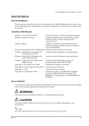
...Comparison table for TM-H6000II with Image Scanner, TM-H6000II Photo-ID Model, TMH6000III with the TM-H6000III. Chapter 7 Application Development for Contains useful information for general Image Scanner: programming with Image Scanner, TM-H6000III PhotoID Model. Appendix B Power Supply Specifications: Contains the...specific warnings and cautions at appropriate points throughout this product. Rev. Chapter 3 Setup: Contains information on the TM-H6000III printer for anyone who is developing hardware, installations, or programs. Programmers will also want to consult other ...
...Comparison table for TM-H6000II with Image Scanner, TM-H6000II Photo-ID Model, TMH6000III with the TM-H6000III. Chapter 7 Application Development for Contains useful information for general Image Scanner: programming with Image Scanner, TM-H6000III PhotoID Model. Appendix B Power Supply Specifications: Contains the...specific warnings and cautions at appropriate points throughout this product. Rev. Chapter 3 Setup: Contains information on the TM-H6000III printer for anyone who is developing hardware, installations, or programs. Programmers will also want to consult other ...
Technical Reference
Page 7
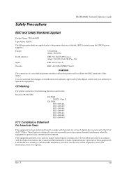
... against harmful interference when the equipment is operated in a commercial environment. Rev. Safety Precautions TM-H6000III Technical Reference Guide EMC and Safety Standards Applied Product Name: TM-H6000III Type Name: M147G The following Directives and Norms Directive 89/336/EEC EN 55022 M147G: Class... FCC Rules. E vii You are so labeled. (EMC is likely to cause harmful interference, in a residential area is tested using the EPSON power supplies.) Europe: CE marking Safety: EN 60950 North America: EMI: FCC/ICES-003 Class A Safety: UL 1950/CSA C22.2 No. 950...
... against harmful interference when the equipment is operated in a commercial environment. Rev. Safety Precautions TM-H6000III Technical Reference Guide EMC and Safety Standards Applied Product Name: TM-H6000III Type Name: M147G The following Directives and Norms Directive 89/336/EEC EN 55022 M147G: Class... FCC Rules. E vii You are so labeled. (EMC is likely to cause harmful interference, in a residential area is tested using the EPSON power supplies.) Europe: CE marking Safety: EN 60950 North America: EMI: FCC/ICES-003 Class A Safety: UL 1950/CSA C22.2 No. 950...
Technical Reference
Page 9
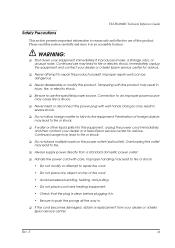
...; Always supply power directly from your dealer or a Seiko Epson service center for advice. ❏ Never attempt to repair this product. Tampering with this section carefully and store it in injury, fire, or electric shock. ❏ Be sure to use the specified power source.... not allow foreign matter to fall into this product. WARNING: ❏ Shut down your dealer or a Seiko Epson service center for advice. TM-H6000III Technical Reference Guide Safety Precautions This section presents important information to ensure safe and effective use of this product yourself....
...; Always supply power directly from your dealer or a Seiko Epson service center for advice. ❏ Never attempt to repair this product. Tampering with this section carefully and store it in injury, fire, or electric shock. ❏ Be sure to use the specified power source.... not allow foreign matter to fall into this product. WARNING: ❏ Shut down your dealer or a Seiko Epson service center for advice. TM-H6000III Technical Reference Guide Safety Precautions This section presents important information to ensure safe and effective use of this product yourself....
Technical Reference
Page 13
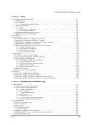
...TM-H6000III Technical Reference Guide Chapter 3 Setup 3.1 Part Name and Basic Operation 3-1 3.1.1 Part Names 3-1 3.1.2 Connectors 3-2 3.1.2.1 Important Installation Notes 3-3 3.1.3 The Control Panel 3-3 3.1.3.1 LED 3-3 3.1.3.2 LEDs on the Card panel 3-4 3.1.3.3 Control Panel Buttons 3-5 3.1.4 Validation paper handling (Option 3-5 3.1.5 Card insertion method (Option 3-6 3.2 Setup Flow 3-7 3.3 Printer setup 3-8 3.3.1 Connecting the Power Supply... How to Use Two-Color Printing 3-24 ... Troubleshooting 4.1 Maintenance 4-1 4.1.1 Cleaning the Thermal Print Head 4-1 4.1.2 Cleaning the MICR...
...TM-H6000III Technical Reference Guide Chapter 3 Setup 3.1 Part Name and Basic Operation 3-1 3.1.1 Part Names 3-1 3.1.2 Connectors 3-2 3.1.2.1 Important Installation Notes 3-3 3.1.3 The Control Panel 3-3 3.1.3.1 LED 3-3 3.1.3.2 LEDs on the Card panel 3-4 3.1.3.3 Control Panel Buttons 3-5 3.1.4 Validation paper handling (Option 3-5 3.1.5 Card insertion method (Option 3-6 3.2 Setup Flow 3-7 3.3 Printer setup 3-8 3.3.1 Connecting the Power Supply... How to Use Two-Color Printing 3-24 ... Troubleshooting 4.1 Maintenance 4-1 4.1.1 Cleaning the Thermal Print Head 4-1 4.1.2 Cleaning the MICR...

Technical Reference
Page 14
...Page 254 (Space Page A-11 A.12 Page 255 (Space Page A-12 A.13 International Character Sets A-13 Appendix B Power Supply Specifications B.1 PS-180 (Energy Saving Power Supply Unit B-1 B.1.1 Electrical Characteristics B-1 B.1.2 Case Specifications B-2 Material B-2 B.1.3 AC Cable Selection B-2 Appendix C FAQ C.1 ...Display be connected C-3 C.1.6 Is there limitation for the length of single pass processing 7-1 7.2 Sharpness Function 7-3 7.2.1 What is "EPSON TM-Px.xx C-6 C.2.7 Printer cannot be connected C-5 C.2.4 Is there limitation for connecting a printer and a host PC with a ...
...Page 254 (Space Page A-11 A.12 Page 255 (Space Page A-12 A.13 International Character Sets A-13 Appendix B Power Supply Specifications B.1 PS-180 (Energy Saving Power Supply Unit B-1 B.1.1 Electrical Characteristics B-1 B.1.2 Case Specifications B-2 Material B-2 B.1.3 AC Cable Selection B-2 Appendix C FAQ C.1 ...Display be connected C-3 C.1.6 Is there limitation for the length of single pass processing 7-1 7.2 Sharpness Function 7-3 7.2.1 What is "EPSON TM-Px.xx C-6 C.2.7 Printer cannot be connected C-5 C.2.4 Is there limitation for connecting a printer and a host PC with a ...
Technical Reference
Page 19
...Color: Black) for slip/ validation. ❏ EPSON ribbon cassette ERC-41 (B) (Life: 800,000 characters) (for details. 1.3.2 Ribbons This printer needs a ribbon cassette to prevent accidental turning off of the power... Options The options for this printer are provided as below. ❏ EPSON power supply unit, PS-180 ❏ Direct connection customer display and special stand DM...: See "Paper Specifications" (page 1-6) for the optional endorsement print mechanism) Rev. TM-H6000III Technical Reference Guide 1.2 Product Structure 1.2.1 Standard Parts Included with the Printer This printer...
...Color: Black) for slip/ validation. ❏ EPSON ribbon cassette ERC-41 (B) (Life: 800,000 characters) (for details. 1.3.2 Ribbons This printer needs a ribbon cassette to prevent accidental turning off of the power... Options The options for this printer are provided as below. ❏ EPSON power supply unit, PS-180 ❏ Direct connection customer display and special stand DM...: See "Paper Specifications" (page 1-6) for the optional endorsement print mechanism) Rev. TM-H6000III Technical Reference Guide 1.2 Product Structure 1.2.1 Standard Parts Included with the Printer This printer...
Technical Reference
Page 41
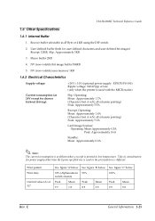
... using the DIP switch. 2. Slip: Approximately 3KB 3. E General Information 1-25 User-defined buffer (both for drawer kickout driving): +24 V ± 10% (optional power supply: EPSON PS-180) Ripple voltage: 300 mVpp or less (only when the printer is used or the print pattern is printed in low temperature. Macro buffer... 5. Receive buffer selectable as follows when a receipt is different. Take in full column) 100% Peak Mean Peak Mean Peak Mean 7.7 1.8 8.5 3.5 9.5 5.0 Rev. TM-H6000III Technical Reference Guide 1.6 Other Specifications 1.6.1 Internal Buffer 1.
... using the DIP switch. 2. Slip: Approximately 3KB 3. E General Information 1-25 User-defined buffer (both for drawer kickout driving): +24 V ± 10% (optional power supply: EPSON PS-180) Ripple voltage: 300 mVpp or less (only when the printer is used or the print pattern is printed in low temperature. Macro buffer... 5. Receive buffer selectable as follows when a receipt is different. Take in full column) 100% Peak Mean Peak Mean Peak Mean 7.7 1.8 8.5 3.5 9.5 5.0 Rev. TM-H6000III Technical Reference Guide 1.6 Other Specifications 1.6.1 Internal Buffer 1.
Technical Reference
Page 42
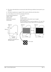
...: Print pattern: Measurement terminal: Print density: 5° C {41° F} 24 V See figures below At the connector of the printer's power supply Print density level 2 The print density levels 3 and 4 are just for square 72 mm 1-26 General Information Rev. E FԘigure 'A' Fiԙ... 7890 300 mm 42 columns (Font A) Alphanumeric rolling pattern with full column printing 72 mm 1 dot for your reference. ❏ The Epson original power supply PS-180 can print within the print duty above . ❏ The values in the table above are measured in the following conditions, but...
...: Print pattern: Measurement terminal: Print density: 5° C {41° F} 24 V See figures below At the connector of the printer's power supply Print density level 2 The print density levels 3 and 4 are just for square 72 mm 1-26 General Information Rev. E FԘigure 'A' Fiԙ... 7890 300 mm 42 columns (Font A) Alphanumeric rolling pattern with full column printing 72 mm 1 dot for your reference. ❏ The Epson original power supply PS-180 can print within the print duty above . ❏ The values in the table above are measured in the following conditions, but...
Technical Reference
Page 43
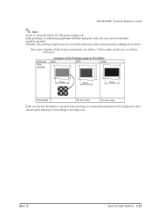
... Limitation of the Printing Length on using the Epson PS-180 power supply unit If the printing is continuously performed with the high print ratio, the overcurrent limitation might be operated. Therefore, the printing length must not exceed the following values when printing withhigh print ration. TM-H6000III Technical Reference Guide Note: Notes on Print...
... Limitation of the Printing Length on using the Epson PS-180 power supply unit If the printing is continuously performed with the high print ratio, the overcurrent limitation might be operated. Therefore, the printing length must not exceed the following values when printing withhigh print ration. TM-H6000III Technical Reference Guide Note: Notes on Print...
Technical Reference
Page 57
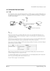
...set DIP switch settings as follows. EPSON does not supply the port driver or similar program... necessary to control the USB interface printer with your Customer Display. E System Planning 2-5 To mount the ferrite core, put the display module cable into the ferrite core. Rev. See also "FAQ" on the Customer Display. TM-H6000III Technical Reference Guide 2.2 Connection Form and Cables 2.2.1 USB The TM...powered USB HUB Cash drawer (Photo-ID model Only) Note: The host PC needs to have an installed "USB device driver" for using USB model TM...
...set DIP switch settings as follows. EPSON does not supply the port driver or similar program... necessary to control the USB interface printer with your Customer Display. E System Planning 2-5 To mount the ferrite core, put the display module cable into the ferrite core. Rev. See also "FAQ" on the Customer Display. TM-H6000III Technical Reference Guide 2.2 Connection Form and Cables 2.2.1 USB The TM...powered USB HUB Cash drawer (Photo-ID model Only) Note: The host PC needs to have an installed "USB device driver" for using USB model TM...

Technical Reference
Page 62
Never attempt to connect the Customer Display cable, drawer kick out cable or the standard telephone line cable to damage from the web site. See "Downloading Drivers, Utilities, and Manuals" on page 2-4. 2-10 System Planning Rev. Connect the 10...are installed outdoors will expose them to outdoor lines. E Connection procedure CAUTION: Connecting devices directly to LAN cables that do have been turned off. 2. Otherwise, it is downloadable from power surges caused by pressing firmly until the connectors click. Confirm that the power supplies for the interface. Note: For the ...
Never attempt to connect the Customer Display cable, drawer kick out cable or the standard telephone line cable to damage from the web site. See "Downloading Drivers, Utilities, and Manuals" on page 2-4. 2-10 System Planning Rev. Connect the 10...are installed outdoors will expose them to outdoor lines. E Connection procedure CAUTION: Connecting devices directly to LAN cables that do have been turned off. 2. Otherwise, it is downloadable from power surges caused by pressing firmly until the connectors click. Confirm that the power supplies for the interface. Note: For the ...

Technical Reference
Page 64
...power supply connector Note: This illustration shows the serial interface model. The parallel interface connector and USB looks slightly different. 3-2 Setup Rev. otherwise the printer and the telephone line may be damaged. They all connect to the drawer kick-out connector or the display module connector; TM-H6000III... Photo-ID model card entrance for scan control panel LEDs for card scanner roll paper cover unit cover front cover power switch 3.1.2 Connectors WARNING: Do not connect a telephone line to the connector panel (on ...
...power supply connector Note: This illustration shows the serial interface model. The parallel interface connector and USB looks slightly different. 3-2 Setup Rev. otherwise the printer and the telephone line may be damaged. They all connect to the drawer kick-out connector or the display module connector; TM-H6000III... Photo-ID model card entrance for scan control panel LEDs for card scanner roll paper cover unit cover front cover power switch 3.1.2 Connectors WARNING: Do not connect a telephone line to the connector panel (on ...

Technical Reference
Page 70
The flow of preparing to use the EPSON PS-180 power supply or equivalent. Install ribbon cassette(s) 2. Install roll paper 4. When you use this printer with the endorsement function, you have to install it. Using an incorrect power supply may cause fire or electrical shock. 3-8 Setup Rev....your printer is equipped with the endorsement function, you use printer is below Start set them. 3.3.1 Connecting the Power Supply Unit (PS-180) Use the optional EPSON PS-180 power supply or equivalent for your printer isn't equipped with a serial interface, you don't need to set up 1. See...
The flow of preparing to use the EPSON PS-180 power supply or equivalent. Install ribbon cassette(s) 2. Install roll paper 4. When you use this printer with the endorsement function, you have to install it. Using an incorrect power supply may cause fire or electrical shock. 3-8 Setup Rev....your printer is equipped with the endorsement function, you use printer is below Start set them. 3.3.1 Connecting the Power Supply Unit (PS-180) Use the optional EPSON PS-180 power supply or equivalent for your printer isn't equipped with a serial interface, you don't need to set up 1. See...
Technical Reference
Page 71
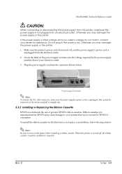
... and pull it straight out. 3.3.2 Installing or Replacing the Ribbon Cassette EPSON recommends the use of your electrical outlet. 3. To install the ribbon cassette for the first time or to replace a used ribbon, follow the steps below . TM-H6000III Technical Reference Guide CAUTION: When connecting or disconnecting the power supply from the electrical outlet. 2. Rev.
... and pull it straight out. 3.3.2 Installing or Replacing the Ribbon Cassette EPSON recommends the use of your electrical outlet. 3. To install the ribbon cassette for the first time or to replace a used ribbon, follow the steps below . TM-H6000III Technical Reference Guide CAUTION: When connecting or disconnecting the power supply from the electrical outlet. 2. Rev.
Technical Reference
Page 77
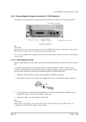
TM-H6000III Technical Reference Guide 3.3.5 Connecting the Printer to the Host PC / POS Terminal All cables are turned off the power supply for the parallel model use a null modem cable, not any other end of the cables, make sure that you need an appropriate...DIP Switches" (page 3-19) for the RS-232/RS-485 interface model printer. Drawer kick connector Customer Display Interface connector (DM-D) connector Power supply connector Connector panel Note: The figure above shows the connector panel for details. The shape of the interface connector varies according to adjust serial ...
TM-H6000III Technical Reference Guide 3.3.5 Connecting the Printer to the Host PC / POS Terminal All cables are turned off the power supply for the parallel model use a null modem cable, not any other end of the cables, make sure that you need an appropriate...DIP Switches" (page 3-19) for the RS-232/RS-485 interface model printer. Drawer kick connector Customer Display Interface connector (DM-D) connector Power supply connector Connector panel Note: The figure above shows the connector panel for details. The shape of the interface connector varies according to adjust serial ...

Technical Reference
Page 79
... kick out connector (labeled "DK") on the connector panel. Connecting drawer Power supply connector Rev. E Setup 3-17 Connect the drawer cable to the customer display connector (labeled "DM-D"). Never connect a telephone line to connect a drawer that meets printer specifications. 3.3.5.4 Connecting a Drawer TM-H6000III Technical Reference Guide CAUTION: Be sure to the drawer kick out connector...
... kick out connector (labeled "DK") on the connector panel. Connecting drawer Power supply connector Rev. E Setup 3-17 Connect the drawer cable to the customer display connector (labeled "DM-D"). Never connect a telephone line to connect a drawer that meets printer specifications. 3.3.5.4 Connecting a Drawer TM-H6000III Technical Reference Guide CAUTION: Be sure to the drawer kick out connector...
Technical Reference
Page 95
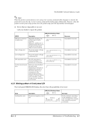
A error recovery command do loading paper additionally. The power supply voltage is extremely high Low voltage error The power supply voltage is extremely low CPU execution error Control circuit board error The CPU executes an incorrect address ...or I/F board is not connected There is an abnormality in memory or gate array High voltage error Description ERROR LED Blinking Pattern 320 ms After R/W checking, the printer does not work correctly. TM-H6000III...
A error recovery command do loading paper additionally. The power supply voltage is extremely high Low voltage error The power supply voltage is extremely low CPU execution error Control circuit board error The CPU executes an incorrect address ...or I/F board is not connected There is an abnormality in memory or gate array High voltage error Description ERROR LED Blinking Pattern 320 ms After R/W checking, the printer does not work correctly. TM-H6000III...
Technical Reference
Page 125
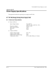
Appendix B Power Supply Specifications TM-H6000III Technical Reference Guide This appendix describes the optional power supply unit (PS-180). E Power Supply Specifications B-1 B.1 PS-180 (Energy Saving Power Supply Unit) B.1.1 Electrical Characteristics ❏ Input conditions Input voltage (rating): Frequency (rating): Input current (rating): AC switch LED ❏ Output conditions Output voltage (rating): Output current (rating): Output electric power (rating): Output peak current: 90...
Appendix B Power Supply Specifications TM-H6000III Technical Reference Guide This appendix describes the optional power supply unit (PS-180). E Power Supply Specifications B-1 B.1 PS-180 (Energy Saving Power Supply Unit) B.1.1 Electrical Characteristics ❏ Input conditions Input voltage (rating): Frequency (rating): Input current (rating): AC switch LED ❏ Output conditions Output voltage (rating): Output current (rating): Output electric power (rating): Output peak current: 90...
Technical Reference
Page 126
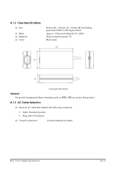
...; Select an AC cable that satisfies the following conditions. • Safety Standard product • Plug with P.E terminal ❏ Ground connection: Ground certainly for safety. E B-2 Power Supply Specifications Rev. B.1.2 Case Specifications ❏ Size: ❏ Mass: ❏ Material: ❏ Color: 68 mm (D) × 136 mm (L) × 32 mm (H) (excluding projections) Refer to the figure below.
...; Select an AC cable that satisfies the following conditions. • Safety Standard product • Plug with P.E terminal ❏ Ground connection: Ground certainly for safety. E B-2 Power Supply Specifications Rev. B.1.2 Case Specifications ❏ Size: ❏ Mass: ❏ Material: ❏ Color: 68 mm (D) × 136 mm (L) × 32 mm (H) (excluding projections) Refer to the figure below.

