
Technical Reference
Page 13
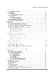
... Data With Serial Interface 4-8 4.2.7 Hexadecimal Dump 4-8 Rev. E xiii TM-H6000III Technical Reference Guide Chapter 3 Setup 3.1 Part Name and Basic Operation 3-1 3.1.1 Part Names 3-1 3.1.2 Connectors 3-2 3.1.2.1 Important Installation Notes 3-3 3.1.3 The Control Panel 3-3 3.1.3.1 LED 3-3 3.1.3.2 LEDs on the Card panel 3-4 3.1.3.3 Control Panel Buttons 3-5 3.1.4 Validation paper handling (Option 3-5 3.1.5 Card insertion method (Option 3-6 3.2 Setup Flow 3-7 3.3 Printer setup 3-8 3.3.1 Connecting the Power Supply Unit (PS-180 3-8 3.3.2 Installing or Replacing the Ribbon...
... Data With Serial Interface 4-8 4.2.7 Hexadecimal Dump 4-8 Rev. E xiii TM-H6000III Technical Reference Guide Chapter 3 Setup 3.1 Part Name and Basic Operation 3-1 3.1.1 Part Names 3-1 3.1.2 Connectors 3-2 3.1.2.1 Important Installation Notes 3-3 3.1.3 The Control Panel 3-3 3.1.3.1 LED 3-3 3.1.3.2 LEDs on the Card panel 3-4 3.1.3.3 Control Panel Buttons 3-5 3.1.4 Validation paper handling (Option 3-5 3.1.5 Card insertion method (Option 3-6 3.2 Setup Flow 3-7 3.3 Printer setup 3-8 3.3.1 Connecting the Power Supply Unit (PS-180 3-8 3.3.2 Installing or Replacing the Ribbon...

Technical Reference
Page 18
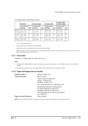
... be connected (available only for the serial interface model) ❏ NV (Non-volatile) bit image buffer (384 KB) * ❏ NV (Non-volatile) user memory (1 KB) * ❏ A counter function that allows checking the printer by remote maintenance ❏ Several interface models (USB, RS-232, bidirectional parallel, Ethernet) are supported * The memory size can be scanned as using bidirectional, minimum distance printing. ❏ Page mode for flexibility in the printer status ❏ Windows® printer driver is...
... be connected (available only for the serial interface model) ❏ NV (Non-volatile) bit image buffer (384 KB) * ❏ NV (Non-volatile) user memory (1 KB) * ❏ A counter function that allows checking the printer by remote maintenance ❏ Several interface models (USB, RS-232, bidirectional parallel, Ethernet) are supported * The memory size can be scanned as using bidirectional, minimum distance printing. ❏ Page mode for flexibility in the printer status ❏ Windows® printer driver is...

Technical Reference
Page 20
... one space page) Multilingual character model supports printing with one of dots per 25.4 mm {1"}] Printing direction: Unidirectional with friction feed Printing width: 72 mm {2.83"}, 512 dot positions Paper width: 79.5 ± 0.5mm {3.13 ± 0.02"} Characters per second) Ladder barcode/2-dimensional code printing: 118 mm/s {4.65"/s} maximum Two-color print mode: 78 mm/s {3.07"/s} maximum (at 24V, density level 2) Paper feed speed: Approximately 200 mm/s {7.9"/s} continuous feeding Line spacing (default): 4.23 mm {1/6"}, programmable by control command. E Print speed...
... one space page) Multilingual character model supports printing with one of dots per 25.4 mm {1"}] Printing direction: Unidirectional with friction feed Printing width: 72 mm {2.83"}, 512 dot positions Paper width: 79.5 ± 0.5mm {3.13 ± 0.02"} Characters per second) Ladder barcode/2-dimensional code printing: 118 mm/s {4.65"/s} maximum Two-color print mode: 78 mm/s {3.07"/s} maximum (at 24V, density level 2) Paper feed speed: Approximately 200 mm/s {7.9"/s} continuous feeding Line spacing (default): 4.23 mm {1/6"}, programmable by control command. E Print speed...
Technical Reference
Page 21
... a font mode such as emphasized mode, some words may be hard to 64 times the standard size. * When using Font B in advance when using Font B. 1.4.1.1 Autocutter Partial cut: Cutting with one point left uncut NOTE: 1. Micro switch NOTE: You can be scaled up to read. To prevent dot displacement, after cutting, feed paper approximately 1 mm (14/360 inches) or more than 40 mm {1.57"} before printing. 2. TM-H6000III Technical Reference Guide Character size, characters per line...
... a font mode such as emphasized mode, some words may be hard to 64 times the standard size. * When using Font B in advance when using Font B. 1.4.1.1 Autocutter Partial cut: Cutting with one point left uncut NOTE: 1. Micro switch NOTE: You can be scaled up to read. To prevent dot displacement, after cutting, feed paper approximately 1 mm (14/360 inches) or more than 40 mm {1.57"} before printing. 2. TM-H6000III Technical Reference Guide Character size, characters per line...
Technical Reference
Page 24
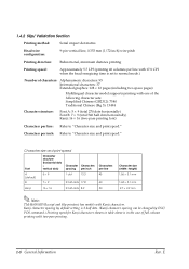
... speed Font Character structure (horizontal dots × vertical dots) Character Characters spacing per inch A (default) 5× 9 1 dot 13.3 B 7× 9 2 half-dots 17.8 Kanji 16 × 16 2 half-dots 8.9 Characters per inch: Refer to "Character size and print speed." Characters per line 45 60 30 Character size (width× height) 1.56 × 3.1 mm 1.24 × 3.1 mm 2.7 × 2.9 mm Note: TM-H6000III (Receipt and Slip printers) has models with Kanji characters. 1.4.2 Slip/ Validation Section Printing method: Serial impact dot matrix Head wire configuration: 9-pin...
... speed Font Character structure (horizontal dots × vertical dots) Character Characters spacing per inch A (default) 5× 9 1 dot 13.3 B 7× 9 2 half-dots 17.8 Kanji 16 × 16 2 half-dots 8.9 Characters per inch: Refer to "Character size and print speed." Characters per line 45 60 30 Character size (width× height) 1.56 × 3.1 mm 1.24 × 3.1 mm 2.7 × 2.9 mm Note: TM-H6000III (Receipt and Slip printers) has models with Kanji characters. 1.4.2 Slip/ Validation Section Printing method: Serial impact dot matrix Head wire configuration: 9-pin...

Technical Reference
Page 39
... offline after printing the current line. E General Information 1-23 TM-H6000III Technical Reference Guide 1.5 Sensors 1.5.1 Paper Sensors 1.5.1.1 Receipt section ❏ Paper roll near-end sensor: • The sensor is removed, the printer enters the paper insertion waiting state. The printer does not proceed to be removed. It detects the presence of paper in the paper path of Form) sensor: • The slip TOF sensor is removed or not. To restart printing, load the paper and set the printer back online...
... offline after printing the current line. E General Information 1-23 TM-H6000III Technical Reference Guide 1.5 Sensors 1.5.1 Paper Sensors 1.5.1.1 Receipt section ❏ Paper roll near-end sensor: • The sensor is removed, the printer enters the paper insertion waiting state. The printer does not proceed to be removed. It detects the presence of paper in the paper path of Form) sensor: • The slip TOF sensor is removed or not. To restart printing, load the paper and set the printer back online...

Technical Reference
Page 40
... recover. The printer goes online when the cover is removed or not after printing. You need to transmit the error recovery command to the next operation until the paper has been removed. 1.5.2 Printer Cover Sensors 1.5.2.1 Receipt section ❏ Paper roll cover open sensor: • When a paper roll is selected as the print sheet, if the sensor detects a cover open during printing, the printer goes offline depending on the setting of bit 8 for the line when the cover open is...
... recover. The printer goes online when the cover is removed or not after printing. You need to transmit the error recovery command to the next operation until the paper has been removed. 1.5.2 Printer Cover Sensors 1.5.2.1 Receipt section ❏ Paper roll cover open sensor: • When a paper roll is selected as the print sheet, if the sensor detects a cover open during printing, the printer goes offline depending on the setting of bit 8 for the line when the cover open is...
Technical Reference
Page 54
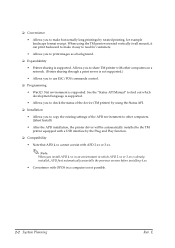
... automatically installed to the TM printer equipped with a USB interface by rotated printing, for customers. • Allows you to print images as a background. ❏ Expandability • Printer sharing is supported. E When using the Status API. ❏ Installation • Allows you to copy the existing settings of the APD environment to other computers on a network. (Printer sharing through a print server is not supported.) • Allows you to use ESC/POS commands control. ❏...
... automatically installed to the TM printer equipped with a USB interface by rotated printing, for customers. • Allows you to print images as a background. ❏ Expandability • Printer sharing is supported. E When using the Status API. ❏ Installation • Allows you to copy the existing settings of the APD environment to other computers on a network. (Printer sharing through a print server is not supported.) • Allows you to use ESC/POS commands control. ❏...
Technical Reference
Page 57
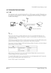
... core. TM-H6000III Technical Reference Guide 2.2 Connection Form and Cables 2.2.1 USB The TM printer can be connected to the host PC via a USB connector, and other TM printers can be connected to the first printer via USB. (See "Changing the DIP Switch Settings" in Chapter 3 for DIP switch settings.) Modular Self-powered USB HUB Cash drawer (Photo-ID model Only) Note: The host PC needs to have an installed "USB device driver" for more details. EPSON does not supply the port driver or...
... core. TM-H6000III Technical Reference Guide 2.2 Connection Form and Cables 2.2.1 USB The TM printer can be connected to the host PC via a USB connector, and other TM printers can be connected to the first printer via USB. (See "Changing the DIP Switch Settings" in Chapter 3 for DIP switch settings.) Modular Self-powered USB HUB Cash drawer (Photo-ID model Only) Note: The host PC needs to have an installed "USB device driver" for more details. EPSON does not supply the port driver or...
Technical Reference
Page 63
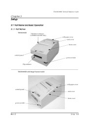
Chapter 3 Setup 3.1 Part Name and Basic Operation 3.1.1 Part Names TM-H6000III Validation entrance (validation model only) TM-H6000III Technical Reference Guide roll paper cover unit cover front cover control panel Slip entrance TM-H6000III with Image Scanner model power switch control panel power switch Rev. E roll paper cover unit cover front cover Setup 3-1
Chapter 3 Setup 3.1 Part Name and Basic Operation 3.1.1 Part Names TM-H6000III Validation entrance (validation model only) TM-H6000III Technical Reference Guide roll paper cover unit cover front cover control panel Slip entrance TM-H6000III with Image Scanner model power switch control panel power switch Rev. E roll paper cover unit cover front cover Setup 3-1
Technical Reference
Page 65
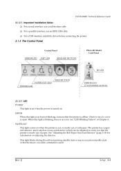
... a parallel interface, use an IEEE 1284 cable. ❏ For a USB interface, install the driver before connecting the printer. 3.1.3 The Control Panel Control Panel ERROR LED SLIP LED RELEASE BUTTON Photo-ID Model Card Panel PAPER OUT LED POWER LED FEED BUTTON ID LED ERROR LED (Card scanner section) 3.1.3.1 LED POWER This light is on when the power is used). Rev. ERROR When this light is blinking, there is offline. This light blinks during the self-test printing standby state or macro execution standby state (when the macro execution command...
... a parallel interface, use an IEEE 1284 cable. ❏ For a USB interface, install the driver before connecting the printer. 3.1.3 The Control Panel Control Panel ERROR LED SLIP LED RELEASE BUTTON Photo-ID Model Card Panel PAPER OUT LED POWER LED FEED BUTTON ID LED ERROR LED (Card scanner section) 3.1.3.1 LED POWER This light is on when the power is used). Rev. ERROR When this light is blinking, there is offline. This light blinks during the self-test printing standby state or macro execution standby state (when the macro execution command...

Technical Reference
Page 83
... be changed after the printer power is turned on, the change setting.) OFF Offline or receive buffer full Print density Print Density 1 (Light) 2↑ 3↓ 4 (Dark) SW 2-3 ON OFF ON OFF SW 2-4 ON OFF OFF ON Rev. TM-H6000III Technical Reference Guide NOTE: Changes in level 4 For a tip about print density, see "When Using Original Paper" (page 3-23). 3.4.3.3 Parallel / Ethernet interface model DIP Switch 1 SW Function 1-1 Auto line feed 1-2 Receive buffer capacity 1-3~ Reserved 1-8 ON Always enabled 45 bytes Fixed to...
... be changed after the printer power is turned on, the change setting.) OFF Offline or receive buffer full Print density Print Density 1 (Light) 2↑ 3↓ 4 (Dark) SW 2-3 ON OFF ON OFF SW 2-4 ON OFF OFF ON Rev. TM-H6000III Technical Reference Guide NOTE: Changes in level 4 For a tip about print density, see "When Using Original Paper" (page 3-23). 3.4.3.3 Parallel / Ethernet interface model DIP Switch 1 SW Function 1-1 Auto line feed 1-2 Receive buffer capacity 1-3~ Reserved 1-8 ON Always enabled 45 bytes Fixed to...
Technical Reference
Page 84
... DIP switch settings (excluding switch 2-8, interface reset signal) are recognized only when the printer power is turned on the signal state. Changes in level 4 For a tip about print density, see "When Using Original Paper" (page 3-23). 3.4.3.4 USB interface model DIP Switch 1 SW Function 1-1 Auto line feed 1-2 Receive buffer capacity 1-3~ Reserved 1-8 ON Always enabled 45 bytes Fixed to OFF OFF Always disabled 4KB DIP Switch 2 SW Function ON OFF 2-1 Handshaking (BUSY condition) Receive buffer full Offline or receive buffer full 2-2 Customer display connection Connected...
... DIP switch settings (excluding switch 2-8, interface reset signal) are recognized only when the printer power is turned on the signal state. Changes in level 4 For a tip about print density, see "When Using Original Paper" (page 3-23). 3.4.3.4 USB interface model DIP Switch 1 SW Function 1-1 Auto line feed 1-2 Receive buffer capacity 1-3~ Reserved 1-8 ON Always enabled 45 bytes Fixed to OFF OFF Always disabled 4KB DIP Switch 2 SW Function ON OFF 2-1 Handshaking (BUSY condition) Receive buffer full Offline or receive buffer full 2-2 Customer display connection Connected...

Technical Reference
Page 85
...switch are software switches. "Downloading Drivers, Utilities, and Manuals" on each paper specification. Rev. TM-H6000III Technical Reference Guide 3.4.3.5 When Using Original Paper When you don't need to set these items automatically. You can change the setting) 6 Error signal output: Disabled Error signal output: Enabled 7 Slip paper jam detection: Disabled Slip paper jam detection: Enabled 8 Becomes recoverable error if the unit cover and Goes offline if the unit cover and front cover is open during printing front cover is turned off, the settings are able to adjust...
...switch are software switches. "Downloading Drivers, Utilities, and Manuals" on each paper specification. Rev. TM-H6000III Technical Reference Guide 3.4.3.5 When Using Original Paper When you don't need to set these items automatically. You can change the setting) 6 Error signal output: Disabled Error signal output: Enabled 7 Slip paper jam detection: Disabled Slip paper jam detection: Enabled 8 Becomes recoverable error if the unit cover and Goes offline if the unit cover and front cover is open during printing front cover is turned off, the settings are able to adjust...

Technical Reference
Page 86
... check the control circuits, printer mechanisms, print quality, control software version, and DIP switch settings. Make sure the printer is turned off and the printer cover is described below. 1. Install two-color thermal paper in the printer. 3. These tests are self tests for both roll paper and slip paper. If the self tests work correctly, the problem is in the other equipment or software, so it completes the self test. E The self test automatically ends and cuts the paper after printing the following , cuts the paper, and pauses. (The PAPER OUT light blinks...
... check the control circuits, printer mechanisms, print quality, control software version, and DIP switch settings. Make sure the printer is turned off and the printer cover is described below. 1. Install two-color thermal paper in the printer. 3. These tests are self tests for both roll paper and slip paper. If the self tests work correctly, the problem is in the other equipment or software, so it completes the self test. E The self test automatically ends and cuts the paper after printing the following , cuts the paper, and pauses. (The PAPER OUT light blinks...
Technical Reference
Page 87
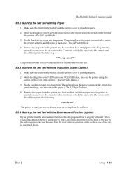
... button, turn on the printer using the switch on the surface side of the printer. ( The SLIP light flashes.) 3. Continue to feed slip paper into the printer to print characters from the printer and feed another validation paper into the printer until the self test prints the following : ***completed*** The printer is ready to receive data as soon as it completes the self test. 3.5.4 Running the Self Test with Slip Paper 1. Make sure the printer is turned off and the printer cover...
... button, turn on the printer using the switch on the surface side of the printer. ( The SLIP light flashes.) 3. Continue to feed slip paper into the printer to print characters from the printer and feed another validation paper into the printer until the self test prints the following : ***completed*** The printer is ready to receive data as soon as it completes the self test. 3.5.4 Running the Self Test with Slip Paper 1. Make sure the printer is turned off and the printer cover...
Technical Reference
Page 95
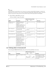
... not work correctly. E Maintenance & Troubleshooting 4-7 A error recovery command do loading paper additionally. The power supply voltage is extremely high Low voltage error The power supply voltage is extremely low CPU execution error Control circuit board error The CPU executes an incorrect address or I/F board is not connected There is caused by card jam. 5120 ms Recovery Fix the card jam according to recover 4.2.5 Blinking pattern of Card panel LED The Card panel ERROR LED flashes, the error have the possibility of "Card Jam...
... not work correctly. E Maintenance & Troubleshooting 4-7 A error recovery command do loading paper additionally. The power supply voltage is extremely high Low voltage error The power supply voltage is extremely low CPU execution error Control circuit board error The CPU executes an incorrect address or I/F board is not connected There is caused by card jam. 5120 ms Recovery Fix the card jam according to recover 4.2.5 Blinking pattern of Card panel LED The Card panel ERROR LED flashes, the error have the possibility of "Card Jam...
Technical Reference
Page 96
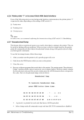
... commands are disabled. 4-8 Maintenance & Troubleshooting Rev. Part of the following errors occurs during serial interface communication, the printer prints "?" This can be useful in finding software problems. When you turn on the setting of DIP switch 1-1. ❏ Parity error ❏ Framing error ❏ Overrun error Note: For other data in a two-column format. To use the hex dump feature, follow these steps: 1. 4.2.6 Printer prints "?" After you find specific commands. or Incorrect Data With Serial Interface If one of a hexadecimal dump is printed for each code...
... commands are disabled. 4-8 Maintenance & Troubleshooting Rev. Part of the following errors occurs during serial interface communication, the printer prints "?" This can be useful in finding software problems. When you turn on the setting of DIP switch 1-1. ❏ Parity error ❏ Framing error ❏ Overrun error Note: For other data in a two-column format. To use the hex dump feature, follow these steps: 1. 4.2.6 Printer prints "?" After you find specific commands. or Incorrect Data With Serial Interface If one of a hexadecimal dump is printed for each code...
Technical Reference
Page 132
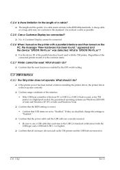
... the USB cable are set to the USB 2.0 standard certification (with a parallel interface and then turned on before installing the printer driver, the printer driver will not operate correctly. ❏ Confirm usage conditions of the interface. • If the USB host controller of the host PC is USB 2.0, a USB 2.0 hub is correct. • Confirm that the reset function is the common name. E Regardless of the connected printer model, it is enabled by the DIP switch setting. C.2.7 Printer...
... the USB cable are set to the USB 2.0 standard certification (with a parallel interface and then turned on before installing the printer driver, the printer driver will not operate correctly. ❏ Confirm usage conditions of the interface. • If the USB host controller of the host PC is USB 2.0, a USB 2.0 hub is correct. • Confirm that the reset function is the common name. E Regardless of the connected printer model, it is enabled by the DIP switch setting. C.2.7 Printer...
Technical Reference
Page 133
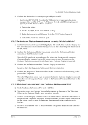
... before turning on the USB interface board. Rev. Turn off the printer and turn on again. TM-H6000III Technical Reference Guide ❏ Confirm that the interface is correctly recognized by the DIP switch of the Customer Display. For correct recognition, be considered for TM Printer Series] appears in the TMUSB package. 3. When the TM printer is set to 19200 bps by the host PC. • Confirm that [EPSON USB Controller for a Customer Display connection? ❏ Fix...
... before turning on the USB interface board. Rev. Turn off the printer and turn on again. TM-H6000III Technical Reference Guide ❏ Confirm that the interface is correctly recognized by the DIP switch of the Customer Display. For correct recognition, be considered for TM Printer Series] appears in the TMUSB package. 3. When the TM printer is set to 19200 bps by the host PC. • Confirm that [EPSON USB Controller for a Customer Display connection? ❏ Fix...


