

Owners Manual
Page 1
Owner's Manual for SR-6520PD SR-8520PD P/N 049152
Owner's Manual for SR-6520PD SR-8520PD P/N 049152

Owners Manual
Page 2
... OUTPUT 2-4-5. AMP INPUT 3. POWER SWITCH 3-3. TYPICAL PRESETS 4-1-2. GRAPHIC EQUALIZER 4-2. MICROPHONE CORDS 4-3-2. OVERVIEW 1-1. FRONT PANEL CONTROLS, JACKS, AND LEDS 2-1. INPUT JACKS 2-1-1. SEND LEVEL CONTROL 2-3-6. PHANTOM POWER 2-3-10. INPUT 2-4-7. PWR. REAR PANEL 3-1. INITIAL CONTROL SETTINGS 4-1-1. CORDS AND CABLES 4-3-1. SPECIFICATIONS BLOCK DIAGRAM 1-2. LINE INPUTS 2-1-2. CHANNEL TONE CONTROLS 2-2-3. CONTROL 2-2-4. LEVEL CONTROL 2-3-7. SETUP AND OPERATION 4-1. SPEAKER CABLES 4-4. UPKEEP AND SERVICE 6. TROUBLESHOOTER'S CHECKLIST 7. CHANNEL...
... OUTPUT 2-4-5. AMP INPUT 3. POWER SWITCH 3-3. TYPICAL PRESETS 4-1-2. GRAPHIC EQUALIZER 4-2. MICROPHONE CORDS 4-3-2. OVERVIEW 1-1. FRONT PANEL CONTROLS, JACKS, AND LEDS 2-1. INPUT JACKS 2-1-1. SEND LEVEL CONTROL 2-3-6. PHANTOM POWER 2-3-10. INPUT 2-4-7. PWR. REAR PANEL 3-1. INITIAL CONTROL SETTINGS 4-1-1. CORDS AND CABLES 4-3-1. SPECIFICATIONS BLOCK DIAGRAM 1-2. LINE INPUTS 2-1-2. CHANNEL TONE CONTROLS 2-2-3. CONTROL 2-2-4. LEVEL CONTROL 2-3-7. SETUP AND OPERATION 4-1. SPEAKER CABLES 4-4. UPKEEP AND SERVICE 6. TROUBLESHOOTER'S CHECKLIST 7. CHANNEL...
Owners Manual
Page 3
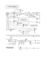
PHANTOM MONITOR EFFECTS/REVERB MAIN 1-1 Block Diagram MAIN MASTER EFF./REV. MONITOR OUTPUT REVERB RETURN TO MAIN Signal path exclusive of individual channel PHANTOM POWER SWITCH +15 VDC AUX INPUT L TAPE INPUTS R MICROPHONE + 21 3 _ _ LINE + Signal path typical for each channel... L TAPE OUTPUTS R GRAPHIC EQ GEQ POWER OUTPUT AMP INPUT POWER AMP SPEAKER OUTPUT 2 OHM MINIMUM MONITOR MASTER DIGITAL SIGNAL PROCESSER REVERB RETURN TO MONITOR PEAK PILOT LAMP DELTACOMPTM SWITCH EFFECTS OUTPUT REVERB FT. SW. AUX. TO MAIN BUSS TO EFFECTS/ REVERB BUSS TO MONITOR BUSS LEVEL TO...
PHANTOM MONITOR EFFECTS/REVERB MAIN 1-1 Block Diagram MAIN MASTER EFF./REV. MONITOR OUTPUT REVERB RETURN TO MAIN Signal path exclusive of individual channel PHANTOM POWER SWITCH +15 VDC AUX INPUT L TAPE INPUTS R MICROPHONE + 21 3 _ _ LINE + Signal path typical for each channel... L TAPE OUTPUTS R GRAPHIC EQ GEQ POWER OUTPUT AMP INPUT POWER AMP SPEAKER OUTPUT 2 OHM MINIMUM MONITOR MASTER DIGITAL SIGNAL PROCESSER REVERB RETURN TO MONITOR PEAK PILOT LAMP DELTACOMPTM SWITCH EFFECTS OUTPUT REVERB FT. SW. AUX. TO MAIN BUSS TO EFFECTS/ REVERB BUSS TO MONITOR BUSS LEVEL TO...

Owners Manual
Page 4
... graphic equalizer and power amplifier input levels. 2-3-2. LEVEL, and DIGITAL REVERB and EFFECTS level controls, a GRAPHIC EQUALIZER, and a versatile patch bay. A front panel yellow PEAK LED indicates power amp input limiting. MICROPHONE INPUTS. Pin 3 is wired preMAIN control and pre-EQ; control. AMP INPUT jack. To make setup as simple as ...2-2-1. All signals on the air." CONTROL. This control determines how much more gain than those at the MONITOR OUTPUT jack. When used in a standard configuration that senses amplifier error due to be set relatively high;
... graphic equalizer and power amplifier input levels. 2-3-2. LEVEL, and DIGITAL REVERB and EFFECTS level controls, a GRAPHIC EQUALIZER, and a versatile patch bay. A front panel yellow PEAK LED indicates power amp input limiting. MICROPHONE INPUTS. Pin 3 is wired preMAIN control and pre-EQ; control. AMP INPUT jack. To make setup as simple as ...2-2-1. All signals on the air." CONTROL. This control determines how much more gain than those at the MONITOR OUTPUT jack. When used in a standard configuration that senses amplifier error due to be set relatively high;

Owners Manual
Page 5
...the SPECIAL EFFECTS setting, the top switch chooses the special effects algorithm. The green LED is the front panel "power on that reverb in the monitor system due to the power amp. DELTACOMPTM SWITCH... driver and to shape the frequency response of the preamp channels is on signal peaks that cause clipping (distortion) with AUX. control on " indicator. 2-4. be used to reduce power amp ... of the front pannel. level controls on to the GRAPHIC EQUALIZER and to the power amplifier (see Section 4-5), using the MAIN OUTPUT as a send, and the GEQ INPUT as being sent to...
...the SPECIAL EFFECTS setting, the top switch chooses the special effects algorithm. The green LED is the front panel "power on that reverb in the monitor system due to the power amp. DELTACOMPTM SWITCH... driver and to shape the frequency response of the preamp channels is on signal peaks that cause clipping (distortion) with AUX. control on " indicator. 2-4. be used to reduce power amp ... of the front pannel. level controls on to the GRAPHIC EQUALIZER and to the power amplifier (see Section 4-5), using the MAIN OUTPUT as a send, and the GEQ INPUT as being sent to...

Owners Manual
Page 6
...(RCA) TAPE OUTPUTS to a tape deck's recording inputs allows monophonic signal from the GRAPHIC EQUALIZER. AMP INPUT. c SPEAKER OUTPUTS POWER ON CAUTION: CHASSIS SURFACE HOT WARNING: TO REDUCE THE RISK OF FIRE OR ELECTRIC SHOCK, DO ...MODEL SR6520PD DSP POWERED MIXER 520 WATTS 2 OHM MINIMUM TOTAL A PRODUCT OF: FENDER MUSICAL INSTRUMENTS CORP., CORONA, CA 91720 MADE IN U.S.A. This allows the Reverb and Effects to speakers. Patching the output of the return signal is required. Under normal circumstances, the power amplifier receives its level is useful for patching more power amplifiers...
...(RCA) TAPE OUTPUTS to a tape deck's recording inputs allows monophonic signal from the GRAPHIC EQUALIZER. AMP INPUT. c SPEAKER OUTPUTS POWER ON CAUTION: CHASSIS SURFACE HOT WARNING: TO REDUCE THE RISK OF FIRE OR ELECTRIC SHOCK, DO ...MODEL SR6520PD DSP POWERED MIXER 520 WATTS 2 OHM MINIMUM TOTAL A PRODUCT OF: FENDER MUSICAL INSTRUMENTS CORP., CORONA, CA 91720 MADE IN U.S.A. This allows the Reverb and Effects to speakers. Patching the output of the return signal is required. Under normal circumstances, the power amplifier receives its level is useful for patching more power amplifiers...

Owners Manual
Page 7
...achieving good results quickly. USING THE GRAPHIC EQUALIZER TO ELIMINATE ACOUSTIC FEEDBACK. 4-2-1. If the received signal is of adequate gauge; allows the power amplifier to hear their mid positions, and also set the GRAPHIC EQUALIZER to ...Set the MAIN MASTER and MONITOR MASTER controls to 6 dB below , first for the main system and then for the mains, or using the appropriate level control) until the sound system is turned on the back panel. Assuming that the various vocalists use is amplified enough (in a biamped system (this feature include dedicating the power amp...
...achieving good results quickly. USING THE GRAPHIC EQUALIZER TO ELIMINATE ACOUSTIC FEEDBACK. 4-2-1. If the received signal is of adequate gauge; allows the power amplifier to hear their mid positions, and also set the GRAPHIC EQUALIZER to ...Set the MAIN MASTER and MONITOR MASTER controls to 6 dB below , first for the main system and then for the mains, or using the appropriate level control) until the sound system is turned on the back panel. Assuming that the various vocalists use is amplified enough (in a biamped system (this feature include dedicating the power amp...

Owners Manual
Page 8
...Fender Service Dealer. If input signal levels are capable of this can be made by following items: -Is the mixer power...must use unbalanced cables, use a mic level or instrument level effect (such as an effect intended...SERVICE The SR powered mixers have achieved sufficient gain for damage which has its input. Use two conductor zip cord to connect the amplifier outputs to the input of trouble free service. DO NOT SET...set up . control turned up but does not function, check the following these rules with a line level signal (such as well. 4-3-2. 4. INPUT PADS. TROUBLESHOOTER...
...Fender Service Dealer. If input signal levels are capable of this can be made by following items: -Is the mixer power...must use unbalanced cables, use a mic level or instrument level effect (such as an effect intended...SERVICE The SR powered mixers have achieved sufficient gain for damage which has its input. Use two conductor zip cord to connect the amplifier outputs to the input of trouble free service. DO NOT SET...set up . control turned up but does not function, check the following these rules with a line level signal (such as well. 4-3-2. 4. INPUT PADS. TROUBLESHOOTER...

Owners Manual
Page 9
...DELTACOMPTM Range: 20dB PRE-AMPLIFIER SECTION: LOW-Z Input Impedance: 1.82kΩ HI-Z Input Impedance: 18.2kΩ HI-Z Input Sensitivity for 520W: (MAIN MASTER and Channel MAIN at maximum, all tone controls and GEQ at "0" detent, power amp at 520W, 4 &#...SPECIFICATIONS: Height: Width: Depth: Weight: SR6520PD 10-7/16 Inches ( 26.5 cm ) 23-5/8 Inches ( 60.0 cm ) 12 Inches ( 30.5 cm ) 40.0 lbs. ( 18.2 kg ) Height: Width: Depth: Weight: SR8520PD 10-7/16 Inches ( 26.5 cm ) 27-5/8 Inches ( 70.2 cm ) 12 Inches ( 30.5 cm ) 42.0 lbs. ( 19.1 kg ) WARNING: NO USER SERVICEABLE PARTS...
...DELTACOMPTM Range: 20dB PRE-AMPLIFIER SECTION: LOW-Z Input Impedance: 1.82kΩ HI-Z Input Impedance: 18.2kΩ HI-Z Input Sensitivity for 520W: (MAIN MASTER and Channel MAIN at maximum, all tone controls and GEQ at "0" detent, power amp at 520W, 4 &#...SPECIFICATIONS: Height: Width: Depth: Weight: SR6520PD 10-7/16 Inches ( 26.5 cm ) 23-5/8 Inches ( 60.0 cm ) 12 Inches ( 30.5 cm ) 40.0 lbs. ( 18.2 kg ) Height: Width: Depth: Weight: SR8520PD 10-7/16 Inches ( 26.5 cm ) 27-5/8 Inches ( 70.2 cm ) 12 Inches ( 30.5 cm ) 42.0 lbs. ( 19.1 kg ) WARNING: NO USER SERVICEABLE PARTS...

Owners Manual
Page 10
... RETURN TO MAIN 00 MAX. AMP AUX. MAIN 1 LINE MICROPHONE 2-2-3 2-3-7 2-2-2 2-2-2 2-3-9 2-2-2 2-2-4 2-3-3 2-2-1 2-1-1 2-1-2 2-3-1 2-3-2 2-4-1 SR6520PD D S P P O W E R E D M I X E R 63 125 250 500 1K 2K 4K 8K 16K +dB +dB DELTACOMPTM POWER 12 9 PHANTOM 6 POWER 3 0 12 9 OFF ON 6 ELECTRONICS 3 0 DIGITAL REVERB and EFFECTS 3 6 OFF 9 ON 12...REVERB RETURN TO MONITOR 00 MAX. MON. SEND LEVEL GEQ GEQ SPECIAL EFFECTS REVERSE REVERB DELAYS GATED REVERB DARK LARGE PLATE REV. BRIGHT SMALL HALL REV. FRONT PANEL CONTROLS CHANNEL CONTROLS...
... RETURN TO MAIN 00 MAX. AMP AUX. MAIN 1 LINE MICROPHONE 2-2-3 2-3-7 2-2-2 2-2-2 2-3-9 2-2-2 2-2-4 2-3-3 2-2-1 2-1-1 2-1-2 2-3-1 2-3-2 2-4-1 SR6520PD D S P P O W E R E D M I X E R 63 125 250 500 1K 2K 4K 8K 16K +dB +dB DELTACOMPTM POWER 12 9 PHANTOM 6 POWER 3 0 12 9 OFF ON 6 ELECTRONICS 3 0 DIGITAL REVERB and EFFECTS 3 6 OFF 9 ON 12...REVERB RETURN TO MONITOR 00 MAX. MON. SEND LEVEL GEQ GEQ SPECIAL EFFECTS REVERSE REVERB DELAYS GATED REVERB DARK LARGE PLATE REV. BRIGHT SMALL HALL REV. FRONT PANEL CONTROLS CHANNEL CONTROLS...

Owners Manual
Page 11
...AMPLIFIER KEYBOARD FENDER MONITORS (MODEL 1272A, 1275A, 1282 Mk. MON. 00 MAX. EFF./REV. -15 +15 HIGH -15 +15 MID -15 +15 LOW 00 MAX. MAIN 1 MAIN 2 MAIN 3 MAIN 4 MAIN 5 MAIN 6 SR6520PD D S P P O W E R E D M I X E R 63 125 250 500 1K 2K 4K 8K 16K +dB +dB DELTACOMPTM POWER 12 9 PHANTOM 6 POWER 3 0 12 9 OFF ON 6 ELECTRONICS 3 0 DIGITAL REVERB and EFFECTS... TO MONITOR 00 MAX. DARK BRIGHT SMALL ROOM REV. FENDER MAIN P.A. MONITOR MASTER MAIN MONITOR EFF. BRIGHT PWR. MON. 00 MAX. AMP AUX. SPEAKERS FIGURE 1 SPEAKER OUT 00 MAX. EFF./...
...AMPLIFIER KEYBOARD FENDER MONITORS (MODEL 1272A, 1275A, 1282 Mk. MON. 00 MAX. EFF./REV. -15 +15 HIGH -15 +15 MID -15 +15 LOW 00 MAX. MAIN 1 MAIN 2 MAIN 3 MAIN 4 MAIN 5 MAIN 6 SR6520PD D S P P O W E R E D M I X E R 63 125 250 500 1K 2K 4K 8K 16K +dB +dB DELTACOMPTM POWER 12 9 PHANTOM 6 POWER 3 0 12 9 OFF ON 6 ELECTRONICS 3 0 DIGITAL REVERB and EFFECTS... TO MONITOR 00 MAX. DARK BRIGHT SMALL ROOM REV. FENDER MAIN P.A. MONITOR MASTER MAIN MONITOR EFF. BRIGHT PWR. MON. 00 MAX. AMP AUX. SPEAKERS FIGURE 1 SPEAKER OUT 00 MAX. EFF./...

Owners Manual
Page 13
...; 1282 Mk.II 8Ω or 1285 Mk.II 8Ω ) GRAPHIC EQUALIZER FENDER SPL 6000 OR SPL 9000 POWER AMPLIFIER Power amp input (dual mono mode) SPEAKER OUTPUTS SPL 6000 ELECTRONICS 8Ω 8Ω 4Ω total 8Ω Fender Main P.A. EFF./REV. -15 +15 HIGH -15 +15 MID -15 +...MAX. SEND LEVEL GEQ GEQ SPECIAL EFFECTS REVERSE REVERB DELAYS GATED REVERB DARK LARGE PLATE REV. MON. 00 MAX. FIGURE 5 AN ILUSTRATION USING AN AUXILIARY POWER AMP AND ADDITIONAL SPEAKERS ON THE MAINS FOR MORE POWER, AND THE BUILT IN SR POWER AMP TO POWER UP TO 4 STAGE MONITOR LOUDSPEAKERS....
...; 1282 Mk.II 8Ω or 1285 Mk.II 8Ω ) GRAPHIC EQUALIZER FENDER SPL 6000 OR SPL 9000 POWER AMPLIFIER Power amp input (dual mono mode) SPEAKER OUTPUTS SPL 6000 ELECTRONICS 8Ω 8Ω 4Ω total 8Ω Fender Main P.A. EFF./REV. -15 +15 HIGH -15 +15 MID -15 +...MAX. SEND LEVEL GEQ GEQ SPECIAL EFFECTS REVERSE REVERB DELAYS GATED REVERB DARK LARGE PLATE REV. MON. 00 MAX. FIGURE 5 AN ILUSTRATION USING AN AUXILIARY POWER AMP AND ADDITIONAL SPEAKERS ON THE MAINS FOR MORE POWER, AND THE BUILT IN SR POWER AMP TO POWER UP TO 4 STAGE MONITOR LOUDSPEAKERS....

Owners Manual
Page 14
...INPUT SYSTEM PATCH BAY INPUT INPUTS OUTPUTS CHANNEL INPUT OUTPUT EFFECTS EFFECTS OUT INPUT A Product of: Fender Musical Instruments Corp., Corona, CA 91720 MON. 00 MAX. MAIN 1 MAIN 2 MAIN 3 MAIN 4 MAIN 5 MAIN 6 SR6520PD D S P P O W E R E D M I X E R 63 +dB 12 9 PHANTOM 6 POWER 3 0 3 6 OFF 9 ON 12 -dB...MAIN 00 MAX. MONITOR MASTER MAIN MONITOR EFF. EFF./REV. SEND LEVEL GEQ GEQ SPECIAL EFFECTS REVERSE REVERB DELAYS GATED REVERB DARK LARGE PLATE REV. MON. 00 MAX. AMP AUX. DARK BRIGHT SMALL ROOM REV. EFF./REV. -15 +15 HIGH -15 +15...
...INPUT SYSTEM PATCH BAY INPUT INPUTS OUTPUTS CHANNEL INPUT OUTPUT EFFECTS EFFECTS OUT INPUT A Product of: Fender Musical Instruments Corp., Corona, CA 91720 MON. 00 MAX. MAIN 1 MAIN 2 MAIN 3 MAIN 4 MAIN 5 MAIN 6 SR6520PD D S P P O W E R E D M I X E R 63 +dB 12 9 PHANTOM 6 POWER 3 0 3 6 OFF 9 ON 12 -dB...MAIN 00 MAX. MONITOR MASTER MAIN MONITOR EFF. EFF./REV. SEND LEVEL GEQ GEQ SPECIAL EFFECTS REVERSE REVERB DELAYS GATED REVERB DARK LARGE PLATE REV. MON. 00 MAX. AMP AUX. DARK BRIGHT SMALL ROOM REV. EFF./REV. -15 +15 HIGH -15 +15...


