
Owner Manual
Page 2
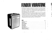
... TREMOLO ASSEMBLY MOTOR ADJUSTMENT MOTOR CLEANING MOTOR OILING MOTOR REMOVAL ORDERING PARTS ROTOR OILING SET-UP INSTRUCTIONS SPECIFICATIONS TREMOLO UNIT INSTALLATION TREMOLO UNIT REMOVAL TWO-SPEED MOTOR ASSEMBLY PAGE 7 1 3 9 5 5 4 4 7 4 2 3 7 4 8 The Vibratone incorporates the famed Leslie® Vibrato Speaker System which, 4 when used in conjunction with the Fender Vibratone. This maintains a constant clean mid-range tremolo tone in - 3 cluding guitar...
... TREMOLO ASSEMBLY MOTOR ADJUSTMENT MOTOR CLEANING MOTOR OILING MOTOR REMOVAL ORDERING PARTS ROTOR OILING SET-UP INSTRUCTIONS SPECIFICATIONS TREMOLO UNIT INSTALLATION TREMOLO UNIT REMOVAL TWO-SPEED MOTOR ASSEMBLY PAGE 7 1 3 9 5 5 4 4 7 4 2 3 7 4 8 The Vibratone incorporates the famed Leslie® Vibrato Speaker System which, 4 when used in conjunction with the Fender Vibratone. This maintains a constant clean mid-range tremolo tone in - 3 cluding guitar...
Owner Manual
Page 3
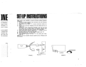
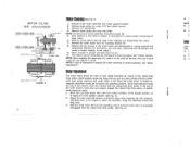
...power switch at "U" position. 2. Make certain that crossover assembly "E" is turned off before making Vibratone installation. 1. Plug phone plug "C" into phone jack recepticle "B". NOTE: Do not use amplifier external speaker jack as Vibratone will not function. Plug amplifi r speaker cord jack "A" into input "D". 7. INF ler Vibratone... Vibratone into wall outlet and turn on switch "T". Remove phone plug "A" from amplifier speaker jack "D". 6. PAGE 7 1 3 9 5 5 4 4 7 4 2 3 7 4 8 CROSSOVER O PLUG TO 'D K RECEPTACLE FIGURE 1 PLUG REMOVE FROM AMP SPEAKER CORD Y-2 AMP FUSE ...
...power switch at "U" position. 2. Make certain that crossover assembly "E" is turned off before making Vibratone installation. 1. Plug phone plug "C" into phone jack recepticle "B". NOTE: Do not use amplifier external speaker jack as Vibratone will not function. Plug amplifi r speaker cord jack "A" into input "D". 7. INF ler Vibratone... Vibratone into wall outlet and turn on switch "T". Remove phone plug "A" from amplifier speaker jack "D". 6. PAGE 7 1 3 9 5 5 4 4 7 4 2 3 7 4 8 CROSSOVER O PLUG TO 'D K RECEPTACLE FIGURE 1 PLUG REMOVE FROM AMP SPEAKER CORD Y-2 AMP FUSE ...
Owner Manual
Page 4
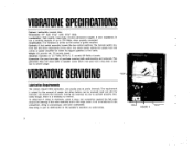
The tremolo switch controls fast and slow movements of power. The Leslie switch selects the output from date of usage, but other factors can absorb the lubricant, leaving the bearings too dry to ... motor. Generally though, there is driven by the combo or guitar amplifier. VIBRATOR SPECIFICATIONS Cabinet: Leatherette covered case. Weight 63 pounds net, 70 pounds boxed. VIBRATOR SERVICING Lubrication Requirements The motors require little lubrication, and usually only at yearly intervals. Amplification: The Vibratone is a tendency to operate properly. Controls: A foot switch assembly...
The tremolo switch controls fast and slow movements of power. The Leslie switch selects the output from date of usage, but other factors can absorb the lubricant, leaving the bearings too dry to ... motor. Generally though, there is driven by the combo or guitar amplifier. VIBRATOR SPECIFICATIONS Cabinet: Leatherette covered case. Weight 63 pounds net, 70 pounds boxed. VIBRATOR SERVICING Lubrication Requirements The motors require little lubrication, and usually only at yearly intervals. Amplification: The Vibratone is a tendency to operate properly. Controls: A foot switch assembly...
Owner Manual
Page 5
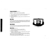
.... Remove "U" bracket (B). 4. NOTE: The large pulley should now be removed simply by reversing the above procedure. See "Motor Adjustment". 4 Remove small motor assembly and support bracket. 2. Disconnect power before proceeding. 1. Remove the tremolo unit mounting screws (2) and gently lift out tre• molo unit. The motor assembly should be absorbed. (A maximum of... either side of 10 drops.) 5. With the speaker lying on either the rotor assembly or the motor assembly from the connector box. 3. Remove large pulley (A) using 3/32 hex (alien) wrench. 3.
.... Remove "U" bracket (B). 4. NOTE: The large pulley should now be removed simply by reversing the above procedure. See "Motor Adjustment". 4 Remove small motor assembly and support bracket. 2. Disconnect power before proceeding. 1. Remove the tremolo unit mounting screws (2) and gently lift out tre• molo unit. The motor assembly should be absorbed. (A maximum of... either side of 10 drops.) 5. With the speaker lying on either the rotor assembly or the motor assembly from the connector box. 3. Remove large pulley (A) using 3/32 hex (alien) wrench. 3.
Owner Manual
Page 6
...the shaft all parts in about 5-8 seconds), using 3/32 hex (alien) wrench. 3. Adjust the rotor drive belt tension so that the small motor is off. Remove large pulley (A) using the adjusting screws... and wing nuts. 3. If the end of large motor. 6. Raise the mounting board, with rotor and motors installed, to full ...(B). 4. NOTE: Do not remove motor assembly mounting bracket (G). 5. Remove small motor assembly and motor support bracket. 2. Remove small pulley and snap ring (H&I Instl FOR THE 1. See "Motor Adjustment". NOTE...
...the shaft all parts in about 5-8 seconds), using 3/32 hex (alien) wrench. 3. Adjust the rotor drive belt tension so that the small motor is off. Remove large pulley (A) using the adjusting screws... and wing nuts. 3. If the end of large motor. 6. Raise the mounting board, with rotor and motors installed, to full ...(B). 4. NOTE: Do not remove motor assembly mounting bracket (G). 5. Remove small motor assembly and motor support bracket. 2. Remove small pulley and snap ring (H&I Instl FOR THE 1. See "Motor Adjustment". NOTE...
Owner Manual
Page 7
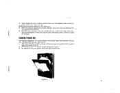
...to seat the bearings. With cabinet standing upright, as shown, tilt tremolo board and position bottom against support. 3. NOTE: Avoid excessive pressure on front and replace other parts and connect wires. ings are mis-aligned. Tilt tremolo up until it cannot move, turn the ...is entirely upright and against support as shown in Fig. 6. 2. When the optimum adjustment has been obtained, secure the motor by tightening the nuts against the laminations. 6. Installing Tremolo unit FOR PROPER ASSEMBLY, TO AVOID RUINING THE ROTOR DRIVE MECHANISM, FOLLOW THE INSTRUCTIONS BELOW: (See Fig. ...
...to seat the bearings. With cabinet standing upright, as shown, tilt tremolo board and position bottom against support. 3. NOTE: Avoid excessive pressure on front and replace other parts and connect wires. ings are mis-aligned. Tilt tremolo up until it cannot move, turn the ...is entirely upright and against support as shown in Fig. 6. 2. When the optimum adjustment has been obtained, secure the motor by tightening the nuts against the laminations. 6. Installing Tremolo unit FOR PROPER ASSEMBLY, TO AVOID RUINING THE ROTOR DRIVE MECHANISM, FOLLOW THE INSTRUCTIONS BELOW: (See Fig. ...
Owner Manual
Page 8
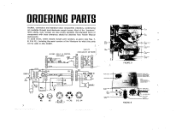
C5 ImIel 3DV HP 01 m xr N. ORDERING PARTS Sockets, connectors and standard value components (resistors, condensers) are also locally available. SW3 C4 .05 600V 7 BLACK GRN • TI BLACK FZ I 2 AMP REL 012385 CABLE & CONTROL S2 2 W 4 GAN 5 ASSEMBLY E 01 1KV C2 SW2 SW 3 BLACK 2 PI SI 3 200MF 30V NP C3 5 5... CENTER OF THE GROMMET 050231 NS FIGURE 8 LINE CORO 026523 PLUG 025437 025717 0216PaLeun Most of the Vibratone for which the parts will be obtained from Fender Musical Instruments. Non - To avoid errors, orders should be used is also helpful.
C5 ImIel 3DV HP 01 m xr N. ORDERING PARTS Sockets, connectors and standard value components (resistors, condensers) are also locally available. SW3 C4 .05 600V 7 BLACK GRN • TI BLACK FZ I 2 AMP REL 012385 CABLE & CONTROL S2 2 W 4 GAN 5 ASSEMBLY E 01 1KV C2 SW2 SW 3 BLACK 2 PI SI 3 200MF 30V NP C3 5 5... CENTER OF THE GROMMET 050231 NS FIGURE 8 LINE CORO 026523 PLUG 025437 025717 0216PaLeun Most of the Vibratone for which the parts will be obtained from Fender Musical Instruments. Non - To avoid errors, orders should be used is also helpful.
Owner Manual
Page 10
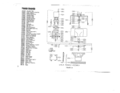
... 015220 O "5 0 0 -0O27240 (512112L)00 LESLIE TREMOLO ASSEMBLY FIGURE 11 Tremolo Assembly 010165 Acoustic Pad 010603 Rotor Support Assembly 010611 Rotor Support 010629 Bearing Assembly 010637 Bearing Plate 010645 Bearing, Oilite 010645 Bearing, Oilite 010660 Bearing Retainer 010678 Bearing Sleeve 010728 Motor ... Small, MOT 1 014084 Grommet 014159 Tire for Drive Wheel 014027 014233 Bushing, Neoprene 017012 Motor "U" Bracket 017301 Rotor Support 017319 Bearing Support 026328 Lock Washer 026500 Screw 10-27x7'/4" 026716 Felt Washer 026740 Screw 8.32x 3/8" 026849 Bracket, "Z" 026880 Motor Assembly...
... 015220 O "5 0 0 -0O27240 (512112L)00 LESLIE TREMOLO ASSEMBLY FIGURE 11 Tremolo Assembly 010165 Acoustic Pad 010603 Rotor Support Assembly 010611 Rotor Support 010629 Bearing Assembly 010637 Bearing Plate 010645 Bearing, Oilite 010645 Bearing, Oilite 010660 Bearing Retainer 010678 Bearing Sleeve 010728 Motor ... Small, MOT 1 014084 Grommet 014159 Tire for Drive Wheel 014027 014233 Bushing, Neoprene 017012 Motor "U" Bracket 017301 Rotor Support 017319 Bearing Support 026328 Lock Washer 026500 Screw 10-27x7'/4" 026716 Felt Washer 026740 Screw 8.32x 3/8" 026849 Bracket, "Z" 026880 Motor Assembly...

Owner Manual
Page 11
... subject to alteration, misuse, ,negligence or accide'rit, or tot the parts of any vibratone which , after regular installation and under this warranty and neither assumes nor authorizes any represent- of_wt-iich, 'have been repaired of replaced by anyone else than an authorized Fender dealer's service contractor, or which have 93haathe sqrialinuenber or ,naroelifi'&-eci, dtpced or...
... subject to alteration, misuse, ,negligence or accide'rit, or tot the parts of any vibratone which , after regular installation and under this warranty and neither assumes nor authorizes any represent- of_wt-iich, 'have been repaired of replaced by anyone else than an authorized Fender dealer's service contractor, or which have 93haathe sqrialinuenber or ,naroelifi'&-eci, dtpced or...


