Calibration Guide
Page 1
Specifications are trademarks of their respective companies. All rights reserved. All product names are subject to change without notice. 123B/124B/125B Industrial ScopeMeter Calibration Manual May 2016 ©2016 Fluke Corporation.
Specifications are trademarks of their respective companies. All rights reserved. All product names are subject to change without notice. 123B/124B/125B Industrial ScopeMeter Calibration Manual May 2016 ©2016 Fluke Corporation.
Calibration Guide
Page 4
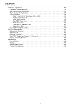
... Foil Removal 44 Display Assembly Removal 44 Maintenance 44 How to Clean 44 Storage 44 Battery Replacement 44 Parts and Accessories 45 ii 123B/124B/125B Calibration Manual Calibration Adjustment 33 Calibration Number and Date 33 Start the Calibration Adjustment 33 Warm Up and Pre-Calibration 34 Final Calibration 34 Delta T Gain...
... Foil Removal 44 Display Assembly Removal 44 Maintenance 44 How to Clean 44 Storage 44 Battery Replacement 44 Parts and Accessories 45 ii 123B/124B/125B Calibration Manual Calibration Adjustment 33 Calibration Number and Date 33 Start the Calibration Adjustment 33 Warm Up and Pre-Calibration 34 Final Calibration 34 Delta T Gain...

Calibration Guide
Page 6
123B/124B/125B Calibration Manual iv
123B/124B/125B Calibration Manual iv

Calibration Guide
Page 8
123B/124B/125B Calibration Manual vi
123B/124B/125B Calibration Manual vi
Calibration Guide
Page 9
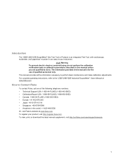
The information provided in this manual unless you are qualified to the 123B/124B/125B Industrial ScopeMeter Users Manual at www.fluke.com. To register your product, visit http://register.fluke.com. XW Warning To prevent electric shock or personal injury, do so. For complete operating instructions, refer to do not perform the calibration verification...
The information provided in this manual unless you are qualified to the 123B/124B/125B Industrial ScopeMeter Users Manual at www.fluke.com. To register your product, visit http://register.fluke.com. XW Warning To prevent electric shock or personal injury, do so. For complete operating instructions, refer to do not perform the calibration verification...

Calibration Guide
Page 10
... requirements before the battery door is not used for the measurement. 2 Look for damaged insulation, exposed metal, or if the wear indicator shows. 123B/124B/125B Calibration Manual Safety Information A Warning identifies hazardous conditions and procedures that are dangerous to the Product or the equipment under test. Check test lead continuity. •...
... requirements before the battery door is not used for the measurement. 2 Look for damaged insulation, exposed metal, or if the wear indicator shows. 123B/124B/125B Calibration Manual Safety Information A Warning identifies hazardous conditions and procedures that are dangerous to the Product or the equipment under test. Check test lead continuity. •...

Calibration Guide
Page 11
...not discard this product as category 9 "Monitoring and Control Instrumentation" product. This product contains a Lithium-ion battery. Contact your authorized Fluke Service Center for recycling information. Do not dispose of the building's low-voltage MAINS installation. A voltage measurement is necessary to the...municipal waste. 3 Battery Safety Approval Measurement Category III is safe to the equipment types in the WEEE Directive Annex I, this manual are explained in this product is visible. • Do not wear loose-fitting clothing or jewelry and keep long hair tied...
...not discard this product as category 9 "Monitoring and Control Instrumentation" product. This product contains a Lithium-ion battery. Contact your authorized Fluke Service Center for recycling information. Do not dispose of the building's low-voltage MAINS installation. A voltage measurement is necessary to the...municipal waste. 3 Battery Safety Approval Measurement Category III is safe to the equipment types in the WEEE Directive Annex I, this manual are explained in this product is visible. • Do not wear loose-fitting clothing or jewelry and keep long hair tied...
Calibration Guide
Page 12
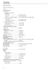
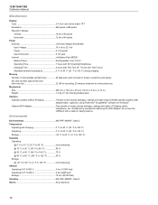
123B/124B/125B Calibration Manual Specifications Dual Input Oscilloscope Vertical Frequency Response DC Coupled without probes and test leads (with BB120) 125B, 124B DC to 40 MHz (-3 dB) 123B DC to 20 MHz (-3 dB) with STL120-IV 1:1 shielded test leads...........DC to 12.5 MHz (-3 dB) / DC to 20 ...
123B/124B/125B Calibration Manual Specifications Dual Input Oscilloscope Vertical Frequency Response DC Coupled without probes and test leads (with BB120) 125B, 124B DC to 40 MHz (-3 dB) 123B DC to 20 MHz (-3 dB) with STL120-IV 1:1 shielded test leads...........DC to 12.5 MHz (-3 dB) / DC to 20 ...
Calibration Guide
Page 13
...Update Free Run, On Trigger Source A, B Sensitivity A and B @ DC to 5 MHz 0.5 divisions or 5 mV @ 40 MHz 125B, 124B 1.5 divisions 123B 4 divisions @ 60 MHz 125B, 124B 4 divisions 123B NA Slope Positive, Negative Advanced Scope Functions Display Modes Normal Captures up to 20 MHz (without test leads or probes... Smooth Suppresses noise from 18 °C to 28 °C. Add 0.1x (specific accuracy) for 5 % to 100 % of amplitude, time base, or trigger level. Manual override by user adjustment of range DC coupled DC to 60 Hz (VAC+DC 1 % + 10 counts) 1 Hz to 60 Hz (VAC 1 % + 10 counts...
...Update Free Run, On Trigger Source A, B Sensitivity A and B @ DC to 5 MHz 0.5 divisions or 5 mV @ 40 MHz 125B, 124B 1.5 divisions 123B 4 divisions @ 60 MHz 125B, 124B 4 divisions 123B NA Slope Positive, Negative Advanced Scope Functions Display Modes Normal Captures up to 20 MHz (without test leads or probes... Smooth Suppresses noise from 18 °C to 28 °C. Add 0.1x (specific accuracy) for 5 % to 100 % of amplitude, time base, or trigger level. Manual override by user adjustment of range DC coupled DC to 60 Hz (VAC+DC 1 % + 10 counts) 1 Hz to 60 Hz (VAC 1 % + 10 counts...
Calibration Guide
Page 14
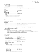
... Hz, 1 kHz, 10 kHz, 100 kHz,1 MHz, 10 MHz, and 50 MHz Frequency Range in Continuous Autoset ...........15 Hz (1 Hz) to 50 MHz Accuracy 125B, 124B @ 1 Hz to 1 MHz 0.5 % + 2 counts) @ 1 MHz to 10 MHz 1.0 % + 2 counts) @ 10 MHz to 70 MHz 2.5 % + 2 counts) 123B @ 1 Hz to 1 MHz 0.5 % + 2 counts) @ 1 MHz to 10 MHz 1.0 %... @ DC >60 dB @ 50 Hz, 60 Hz, or 400 Hz Full Scale Reading 5000 counts, reading is independent of AC or DC coupled. 123B/124B/125B Calibration Manual AC coupled with 1:1 (shielded) test leads 60 Hz (6 Hz with 10:1 probe 1.5 % 50 Hz (5 Hz with 10:1 probe 2 % 33 Hz (3.3 Hz ...
... Hz, 1 kHz, 10 kHz, 100 kHz,1 MHz, 10 MHz, and 50 MHz Frequency Range in Continuous Autoset ...........15 Hz (1 Hz) to 50 MHz Accuracy 125B, 124B @ 1 Hz to 1 MHz 0.5 % + 2 counts) @ 1 MHz to 10 MHz 1.0 % + 2 counts) @ 10 MHz to 70 MHz 2.5 % + 2 counts) 123B @ 1 Hz to 1 MHz 0.5 % + 2 counts) @ 1 MHz to 10 MHz 1.0 %... @ DC >60 dB @ 50 Hz, 60 Hz, or 400 Hz Full Scale Reading 5000 counts, reading is independent of AC or DC coupled. 123B/124B/125B Calibration Manual AC coupled with 1:1 (shielded) test leads 60 Hz (6 Hz with 10:1 probe 1.5 % 50 Hz (5 Hz with 10:1 probe 2 % 33 Hz (3.3 Hz ...
Calibration Guide
Page 16
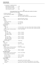
...Time Distance Readout Average, Min, Max and Time Distance Readout (in ROLL mode, instrument in Single Channel Mode) Accuracy As Oscilloscope Accuracy 8 123B/124B/125B Calibration Manual Continuity (CONT) Beep 30 Ω ±5 Ω) in 50 Ω range Measurement Current 0.5 mA Detection of shorts 1 ms Diode ...possible in HOLD) Dual Horizontal Lines High, Low and Peak-Peak Readout Rise or Fall Time Transition Time, 0 %-Level and 100 %-Level Readout (Manual or Auto Leveling; Meter settling time Normal: 2 s @ 1 μs to 10 ms/div. AutoHold works on COM Capacitance (CAP) Ranges ...
...Time Distance Readout Average, Min, Max and Time Distance Readout (in ROLL mode, instrument in Single Channel Mode) Accuracy As Oscilloscope Accuracy 8 123B/124B/125B Calibration Manual Continuity (CONT) Beep 30 Ω ±5 Ω) in 50 Ω range Measurement Current 0.5 mA Detection of shorts 1 ms Diode ...possible in HOLD) Dual Horizontal Lines High, Low and Peak-Peak Readout Rise or Fall Time Transition Time, 0 %-Level and 100 %-Level Readout (Manual or Auto Leveling; Meter settling time Normal: 2 s @ 1 μs to 10 ms/div. AutoHold works on COM Capacitance (CAP) Ranges ...
Calibration Guide
Page 18
... feet) Operating CAT IV 600 V 2 km (6600 feet) Storage 12 km (40 000 feet) Vibration MIL-PRF-28800F, Class 2 Shock 30 g maximum 10 123B/124B/125B Calibration Manual Miscellaneous Display Type 5.7-inch color active matrix TFT Resolution 640 pixels x 480 pixels Waveform Display Vertical 10 div of 40 pixels Horizontal 12 div...
... feet) Operating CAT IV 600 V 2 km (6600 feet) Storage 12 km (40 000 feet) Vibration MIL-PRF-28800F, Class 2 Shock 30 g maximum 10 123B/124B/125B Calibration Manual Miscellaneous Display Type 5.7-inch color active matrix TFT Resolution 640 pixels x 480 pixels Waveform Display Vertical 10 div of 40 pixels Horizontal 12 div...

Calibration Guide
Page 20
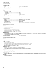
123B/124B/125B Calibration Manual Required Equipment Before you start the verification procedures or make calibration adjustments, refer to ensure that the Test Tool is in good operating condition. Table 2. ...) Dual Banana Jack to Male BNC Adapter (1x) Male BNC to Standby. 12 Turn on the specifications. See the Calibrator Operators Manual. 4. Some of the tests vary because the 124B and 125B have higher vertical and trigger bandwidths than the 123B. The Performance Verification Procedure is calibrated and in illustrations) Used on...
123B/124B/125B Calibration Manual Required Equipment Before you start the verification procedures or make calibration adjustments, refer to ensure that the Test Tool is in good operating condition. Table 2. ...) Dual Banana Jack to Male BNC Adapter (1x) Male BNC to Standby. 12 Turn on the specifications. See the Calibrator Operators Manual. 4. Some of the tests vary because the 124B and 125B have higher vertical and trigger bandwidths than the 123B. The Performance Verification Procedure is calibrated and in illustrations) Used on...

Calibration Guide
Page 21
...select auto ranging (AUTO shows at the top of the sine wave on the display of the Test Tool. 2. Note toggles between Auto and Manual ranging. Industrial ScopeMeter Performance Verification Input A and Input B Tests To verify a measurement, choose items from a menu: 1. Push the B button...; to short circuit the Input A and the Input B shielded banana sockets of the Test Tool. toggles between AUTO and MANUAL ranging. Push . d. Push to confirm the selection and go to the USER OPTIONS menu. 2. Before you need to the...
...select auto ranging (AUTO shows at the top of the sine wave on the display of the Test Tool. 2. Note toggles between Auto and Manual ranging. Industrial ScopeMeter Performance Verification Input A and Input B Tests To verify a measurement, choose items from a menu: 1. Push the B button...; to short circuit the Input A and the Input B shielded banana sockets of the Test Tool. toggles between AUTO and MANUAL ranging. Push . d. Push to confirm the selection and go to the USER OPTIONS menu. 2. Before you need to the...
Calibration Guide
Page 22
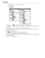
...is set Input B, push and make these selections: • Coupling: DC • Readings: Normal • Noise filter: ON 3. Neither AUTO nor MANUAL show on the display. 4. Repeat step 5 for the trace to become stable. 9. The time base ranging is ±0.025 division (= 1 pixel). 6. Make ...a few seconds for the Input B trace. 7. Remove the Input A and Input B short. 14 The allowed difference is automatic. 123B/124B/125B Calibration Manual e. To set to the same position after the time base changes. On the Test Tool, push to toggle the time base ...
...is set Input B, push and make these selections: • Coupling: DC • Readings: Normal • Noise filter: ON 3. Neither AUTO nor MANUAL show on the display. 4. Repeat step 5 for the trace to become stable. 9. The time base ranging is ±0.025 division (= 1 pixel). 6. Make ...a few seconds for the Input B trace. 7. Remove the Input A and Input B short. 14 The allowed difference is automatic. 123B/124B/125B Calibration Manual e. To set to the same position after the time base changes. On the Test Tool, push to toggle the time base ...
Calibration Guide
Page 23
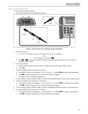
...; if AUTO does not show in the center of the sine wave to -peak. 8. b. Push or to change the sensitivity, to select manual sensitivity ranging, and to Calibrator Scope Output 50 Ω 2. Set up the Test Tool: a. Push . 4. Use to 1.5 divisions. Adjust...not, press to enable for Trigger Level adjustment. On the Calibrator, supply a 40 MHz (123B) or 60 MHz (124B/125B) leveled sine wave of the sine wave to adjust the trigger level and verify that the signal is well triggered. Adjust the amplitude of...
...; if AUTO does not show in the center of the sine wave to -peak. 8. b. Push or to change the sensitivity, to select manual sensitivity ranging, and to Calibrator Scope Output 50 Ω 2. Set up the Test Tool: a. Push . 4. Use to 1.5 divisions. Adjust...not, press to enable for Trigger Level adjustment. On the Calibrator, supply a 40 MHz (123B) or 60 MHz (124B/125B) leveled sine wave of the sine wave to adjust the trigger level and verify that the signal is well triggered. Adjust the amplitude of...
Calibration Guide
Page 24
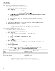
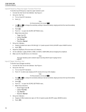
... on 200 mV/div. 3. Table 3. Set up the Calibrator: a. Note For this procedure, do not change the sensitivity, to select manual sensitivity ranging, and to change the amplitude. 6. Push to close the menu. 3. Connect the Test Tool to the Calibrator. ... the same principles as Frequency measurements, the Duty Cycle and Pulse Width measurement function are not verified separately. 16 123B/124B/125B Calibration Manual Input A Frequency Response Upper Transition Point Test To test the Input A frequency response upper transition point: 1. b. Set...
... on 200 mV/div. 3. Table 3. Set up the Calibrator: a. Note For this procedure, do not change the sensitivity, to select manual sensitivity ranging, and to change the amplitude. 6. Push to close the menu. 3. Connect the Test Tool to the Calibrator. ... the same principles as Frequency measurements, the Duty Cycle and Pulse Width measurement function are not verified separately. 16 123B/124B/125B Calibration Manual Input A Frequency Response Upper Transition Point Test To test the Input A frequency response upper transition point: 1. b. Set...
Calibration Guide
Page 26
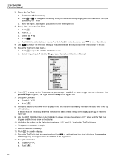
123B/124B/125B Calibration Manual Input B Frequency Response Upper Transition Point Test To test the Input B frequency response upper transition point: 1. b. f. b. Set up the Test Tool: a. Push or to change the sensitivity setting to manual sensitivity ranging and lock the Input B sensitivity on...Input A and Input B AC Input Coupling Test on 200 mV/div. c. Supply a 5 MHz leveled sine wave of the sine wave to manual sensitivity ranging and lock the Input B sensitivity on Input B if necessary. Use and to change the sensitivity setting to ...
123B/124B/125B Calibration Manual Input B Frequency Response Upper Transition Point Test To test the Input B frequency response upper transition point: 1. b. f. b. Set up the Test Tool: a. Push or to change the sensitivity setting to manual sensitivity ranging and lock the Input B sensitivity on...Input A and Input B AC Input Coupling Test on 200 mV/div. c. Supply a 5 MHz leveled sine wave of the sine wave to manual sensitivity ranging and lock the Input B sensitivity on Input B if necessary. Use and to change the sensitivity setting to ...
Calibration Guide
Page 28
123B/124B/125B Calibration Manual 2. Turn on 1 V/div. Push or to change the time base setting to +2 divisions. Push . c. Use to change the sensitivity setting to manual sensitivity ranging and lock the Input A and Input B sensitivity on Input B if necessary. Push to ...Verify that Waiting shows on the status line at the top of the trigger icon. 7. Use to set the trigger level to manual time base ranging and lock the time base on the Calibrator is the top of the display. b. c. Set up the Test Tool: a....
123B/124B/125B Calibration Manual 2. Turn on 1 V/div. Push or to change the time base setting to +2 divisions. Push . c. Use to change the sensitivity setting to manual sensitivity ranging and lock the Input A and Input B sensitivity on Input B if necessary. Push to ...Verify that Waiting shows on the status line at the top of the trigger icon. 7. Use to set the trigger level to manual time base ranging and lock the time base on the Calibrator is the top of the display. b. c. Set up the Test Tool: a....
Calibration Guide
Page 30
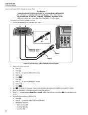
... (1.5 m) PM9092/001 (0.5 m) PM9081 PM9093 Figure 6. b. Select V dc. h. Push . 3. c. Test Tool Input A-B to select manual time base ranging and lock the time base on the calibration source and connecting cables during the following steps. e. Use to change the ... INPUT SETTINGS A menu. Push . Push to toggle between the calibrator and the test tool. Push . 123B/124B/125B Calibration Manual Input A and Input B DC Voltage Accuracy Test XW Warning To prevent possible electrical shock, fire, or personal injury, make sure that...
... (1.5 m) PM9092/001 (0.5 m) PM9081 PM9093 Figure 6. b. Select V dc. h. Push . 3. c. Test Tool Input A-B to select manual time base ranging and lock the time base on the calibration source and connecting cables during the following steps. e. Use to change the ... INPUT SETTINGS A menu. Push . Push to toggle between the calibrator and the test tool. Push . 123B/124B/125B Calibration Manual Input A and Input B DC Voltage Accuracy Test XW Warning To prevent possible electrical shock, fire, or personal injury, make sure that...


