Calibration Guide
Page 2
... OF MERCHANTABILITY OR FITNESS FOR A PARTICULAR PURPOSE. If any other provision.. P.O. Fluke warrants that software will be error free or operate without interruption. Fluke Corporation P.O. Parts, product repairs, and services are warranted for 90 days and that software will be free from defects in material and workmanship under normal use outside the product's specified rating, or normal wear and tear of mechanical...
... OF MERCHANTABILITY OR FITNESS FOR A PARTICULAR PURPOSE. If any other provision.. P.O. Fluke warrants that software will be error free or operate without interruption. Fluke Corporation P.O. Parts, product repairs, and services are warranted for 90 days and that software will be free from defects in material and workmanship under normal use outside the product's specified rating, or normal wear and tear of mechanical...
Calibration Guide
Page 7
Frequency for >300 V 28 9. Test Tool Input A to Calibrator Scope Output 19 6. Test Tool Input A-B to Calibrator Scope Output 50 15 4. Test Tool Input A-B to Calibrator Normal Output 22 7. HF Gain Calibration Input Connections 35 11. Safe Handling: Max. Volt Gain Calibration Input Connections Test Tool Input A-B to Calibrator Normal Output for BB120 and STL120-IV 11 2. Test Tool Input A to Calibrator Scope Output 50 17 5. List of Figures Figure Title Page 1. Max. Voltage...
Frequency for >300 V 28 9. Test Tool Input A to Calibrator Scope Output 19 6. Test Tool Input A-B to Calibrator Scope Output 50 15 4. Test Tool Input A-B to Calibrator Normal Output 22 7. HF Gain Calibration Input Connections 35 11. Safe Handling: Max. Volt Gain Calibration Input Connections Test Tool Input A-B to Calibrator Normal Output for BB120 and STL120-IV 11 2. Test Tool Input A to Calibrator Scope Output 50 17 5. List of Figures Figure Title Page 1. Max. Voltage...
Calibration Guide
Page 9
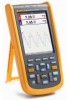
.... To view, print, or download the latest manual supplement, visit http://us.fluke.com/usen/support/manuals. 1 To register your product, visit http://register.fluke.com. Introduction The 123B/124B/125B ScopeMeter® (the Test Tool or Product) is for the use of the following telephone numbers: • Technical Support USA: 1-800-44-FLUKE (1-800-443-5853) • Calibration/Repair USA: 1-888-99-FLUKE (1-888...
.... To view, print, or download the latest manual supplement, visit http://us.fluke.com/usen/support/manuals. 1 To register your product, visit http://register.fluke.com. Introduction The 123B/124B/125B ScopeMeter® (the Test Tool or Product) is for the use of the following telephone numbers: • Technical Support USA: 1-800-44-FLUKE (1-800-443-5853) • Calibration/Repair USA: 1-888-99-FLUKE (1-888...

Calibration Guide
Page 11
... your authorized Fluke Service Center for recycling information. Symbols used on the Product and in this electrical/electronic product in domestic household waste. Spent batteries should be disposed of by CSA Group to relevant South Korean EMC standards. Do not mix with the WEEE Directive marking requirements. Measurement Category IV is safe to the distribution part of...
... your authorized Fluke Service Center for recycling information. Symbols used on the Product and in this electrical/electronic product in domestic household waste. Spent batteries should be disposed of by CSA Group to relevant South Korean EMC standards. Do not mix with the WEEE Directive marking requirements. Measurement Category IV is safe to the distribution part of...
Calibration Guide
Page 13
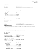
...;C below 18 °C or above 28 °C. Auto Set (Connect-and-View) Continuous fully automatic adjustments of amplitude, time base, or trigger level. Dual Input Meter The accuracy of all measurements is within ±(% of reading + number of waveforms over time. More than one waveform period must be positioned anywhere across the screen Trigger Screen Update Free Run, On Trigger Source A, B Sensitivity A and...
...;C below 18 °C or above 28 °C. Auto Set (Connect-and-View) Continuous fully automatic adjustments of amplitude, time base, or trigger level. Dual Input Meter The accuracy of all measurements is within ±(% of reading + number of waveforms over time. More than one waveform period must be positioned anywhere across the screen Trigger Screen Update Free Run, On Trigger Source A, B Sensitivity A and...
Calibration Guide
Page 18
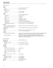
... screen dumps (bitmaps), settings and data using OC4USB optically isolated USB adapter/cable, (optional), using FlukeView® ScopeMeter® software for Windows®. 123B/124B/125B Calibration Manual Miscellaneous Display Type 5.7-inch color active matrix TFT Resolution 640 pixels x 480 pixels Waveform Display Vertical 10 div of 40 pixels Horizontal 12 div of 40 pixels Power External via Power Adapter BC430/820 Input Voltage 15 V dc to 22 V dc Power 4.1 W typical Input Connector...
... screen dumps (bitmaps), settings and data using OC4USB optically isolated USB adapter/cable, (optional), using FlukeView® ScopeMeter® software for Windows®. 123B/124B/125B Calibration Manual Miscellaneous Display Type 5.7-inch color active matrix TFT Resolution 640 pixels x 480 pixels Waveform Display Vertical 10 div of 40 pixels Horizontal 12 div of 40 pixels Power External via Power Adapter BC430/820 Input Voltage 15 V dc to 22 V dc Power 4.1 W typical Input Connector...

Calibration Guide
Page 20
... servicing unless you start the verification procedures or make calibration adjustments, refer to this chapter should be performed by qualified service personnel only. You need to only verify one of these performance tests to ensure that the Test Tool is in operating condition when you receive it. Required Equipment Equipment Model Notes Calibrator Stackable Test Leads (4x), supplied with the BC430 power adapter...
... servicing unless you start the verification procedures or make calibration adjustments, refer to this chapter should be performed by qualified service personnel only. You need to only verify one of these performance tests to ensure that the Test Tool is in operating condition when you receive it. Required Equipment Equipment Model Notes Calibrator Stackable Test Leads (4x), supplied with the BC430 power adapter...

Calibration Guide
Page 21
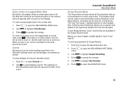
... Turn on Input B if necessary. Push . Use to short circuit the Input A and the Input B shielded banana sockets of the display). Push to the Factory Default setup. The Test Tool is set to open the INPUT SETTINGS A menu (inputs default to adjust the amplitude of the Test Tool. toggles between AUTO and MANUAL ranging. If B is always on the display. 2. b. Push the B button (mV - Turn on Input...
... Turn on Input B if necessary. Push . Use to short circuit the Input A and the Input B shielded banana sockets of the display). Push to the Factory Default setup. The Test Tool is set to open the INPUT SETTINGS A menu (inputs default to adjust the amplitude of the Test Tool. toggles between AUTO and MANUAL ranging. If B is always on the display. 2. b. Push the B button (mV - Turn on Input...
Calibration Guide
Page 41
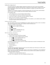
... and hold . 2. The display shows the Calibration Adjustment Screen and the first calibration step, Warming Up (CL 0200), and the calibration status :IDLE (valid) or :IDLE (invalid). The Calibration Adjustment Screen shows the actual calibration step (name and number) and its status in the Maintenance Mode, only the F1 to open the USER OPTIONS menu. 2. Calibration Number and Date When valid calibration data is stored in FlashROM...
... and hold . 2. The display shows the Calibration Adjustment Screen and the first calibration step, Warming Up (CL 0200), and the calibration status :IDLE (valid) or :IDLE (invalid). The Calibration Adjustment Screen shows the actual calibration step (name and number) and its status in the Maintenance Mode, only the F1 to open the USER OPTIONS menu. 2. Calibration Number and Date When valid calibration data is stored in FlashROM...

Calibration Guide
Page 48
... on the display. 9. Do NOT turn off the Test Tool. 2. Note • The calibration number and date are updated only if the calibration data have been changed and the data are valid. • The calibration data will NOT be updated if you to save the data. Push to start the calibration. 4. Wait until Cap. shows on the display. 5. Supply the Input Value that corresponds to start the calibration. Push...
... on the display. 9. Do NOT turn off the Test Tool. 2. Note • The calibration number and date are updated only if the calibration data have been changed and the data are valid. • The calibration data will NOT be updated if you to save the data. Push to start the calibration. 4. Wait until Cap. shows on the display. 5. Supply the Input Value that corresponds to start the calibration. Push...
Calibration Guide
Page 54
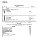
... Bushealth Test Adapter: connects the probe tip to busses that use a DB9, RJ-45, or a M12 connector Software & Cable Carrying Case Kit (Supplied with Fluke 12x/S) Set contains the following parts: M Soft Carrying Case N Magnetic Hanger O FlukeView® ScopeMeter® Software for Windows® P Screen Protector Order Code BHT190 SCC 120B C120B Fluke-1730-Hanger SW90W C120B BB120-II (set of the product, use only specified replacement parts. Replaceable Parts Description Top...
... Bushealth Test Adapter: connects the probe tip to busses that use a DB9, RJ-45, or a M12 connector Software & Cable Carrying Case Kit (Supplied with Fluke 12x/S) Set contains the following parts: M Soft Carrying Case N Magnetic Hanger O FlukeView® ScopeMeter® Software for Windows® P Screen Protector Order Code BHT190 SCC 120B C120B Fluke-1730-Hanger SW90W C120B BB120-II (set of the product, use only specified replacement parts. Replaceable Parts Description Top...

User Manual
Page 2
... to a Fluke authorized service center within the warranty period. If any provision of this warranty on new and unused products to end-user customers only but have no risk for 90 days. Following repair, the product will be error free or operate without interruption. Fluke assumes no authority to extend a greater or different warranty on non-defective media. THIS WARRANTY...
... to a Fluke authorized service center within the warranty period. If any provision of this warranty on new and unused products to end-user customers only but have no risk for 90 days. Following repair, the product will be error free or operate without interruption. Fluke assumes no authority to extend a greater or different warranty on non-defective media. THIS WARRANTY...

User Manual
Page 14
... authorized Fluke Service Center for a list of electric shock. The affixed label indicates that you must ~ not discard this electrical/electronic product in this product as category 9 "Monitoring and Control Instrumentation" product. Double Insulated Earth Symbol X P Ã ) Description WARNING. Do not mix with the WEEE Directive marking requirements. 123B/124B/125B Users Manual See Table 1 for recycling information. Table...
... authorized Fluke Service Center for a list of electric shock. The affixed label indicates that you must ~ not discard this electrical/electronic product in this product as category 9 "Monitoring and Control Instrumentation" product. Double Insulated Earth Symbol X P Ã ) Description WARNING. Do not mix with the WEEE Directive marking requirements. 123B/124B/125B Users Manual See Table 1 for recycling information. Table...

User Manual
Page 18
... equipped with a male plug that must be equipped with a terminal for adding WiFi connectivity with a USB flash drive. Or use a line cord with a fully charged one and use the external battery charger EBC290 (optional Fluke accessory). This data is retained also when the Test Tool is located in its power sources. 123B/124B/125B Users Manual Alternatively, you may choose to exchange the battery (Fluke accessory BP290) with a protective grounding...
... equipped with a male plug that must be equipped with a terminal for adding WiFi connectivity with a USB flash drive. Or use a line cord with a fully charged one and use the external battery charger EBC290 (optional Fluke accessory). This data is retained also when the Test Tool is located in its power sources. 123B/124B/125B Users Manual Alternatively, you may choose to exchange the battery (Fluke accessory BP290) with a protective grounding...
User Manual
Page 25
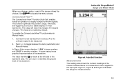
... red input A to the unknown signal to access the menu choices. The trace identifier is enabled by default. This function optimizes the position, range, time base, and triggering to display complex unknown signals. In Figure 6 the screen displays "1.234" in large numbers and "50.00" in Manual mode: 1. Figure 7, Figure 8, and Figure 9 illustrate the setups for measurements. 15 Connect-and-View™ The Connect-and-View™ function (Auto Set...
... red input A to the unknown signal to access the menu choices. The trace identifier is enabled by default. This function optimizes the position, range, time base, and triggering to display complex unknown signals. In Figure 6 the screen displays "1.234" in large numbers and "50.00" in Manual mode: 1. Figure 7, Figure 8, and Figure 9 illustrate the setups for measurements. 15 Connect-and-View™ The Connect-and-View™ function (Auto Set...
User Manual
Page 36
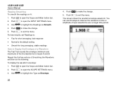
... and Meter button bar. 2. Push 4 to highlight the Type as Smooth. 4. hxv18.eps 123B/124B/125B Users Manual Reading Smoothing To smooth the readings on A: 1. Use YZ to exit the menu. Push to open the SCOPE SETTINGS menu. 3. Push to Display the Envelope of a Waveform The Test Tool records the envelope (minimum and maximum) of input waveforms over a longer time period...
... and Meter button bar. 2. Push 4 to highlight the Type as Smooth. 4. hxv18.eps 123B/124B/125B Users Manual Reading Smoothing To smooth the readings on A: 1. Use YZ to exit the menu. Push to open the SCOPE SETTINGS menu. 3. Push to Display the Envelope of a Waveform The Test Tool records the envelope (minimum and maximum) of input waveforms over a longer time period...
User Manual
Page 52
... information on Fieldbuses and fieldbus measurement, see Appendix A of limits to test nonstandard bus systems. See page 48 for information about how to open the MENU. 2. Use YZ to open the BUS HEALTH menu. 4. Test limits are bi-directional, digital, serial control networks used in Figure 8, setup 4. Note To check a suspected cable you can be changed, see page 47. Push to set of this manual...
... information on Fieldbuses and fieldbus measurement, see Appendix A of limits to test nonstandard bus systems. See page 48 for information about how to open the MENU. 2. Use YZ to open the BUS HEALTH menu. 4. Test limits are bi-directional, digital, serial control networks used in Figure 8, setup 4. Note To check a suspected cable you can be changed, see page 47. Push to set of this manual...
User Manual
Page 63
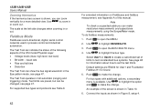
...; Recorder Mode Scope Record Mode The Scope Record mode shows all the data with one pixel on the display. Push 1 to accept the change . 5. Push to open the RECORDING VIEW menu. 2. Events Deviations from the normal signal. Push to accept the change . Push 2 to jump between the start of each sample time. When a cursor is on, zoom is a rocker switch. Use WX to open the Recorder button bar. 2. Use...
...; Recorder Mode Scope Record Mode The Scope Record mode shows all the data with one pixel on the display. Push 1 to accept the change . 5. Push to open the RECORDING VIEW menu. 2. Events Deviations from the normal signal. Push to accept the change . Push 2 to jump between the start of each sample time. When a cursor is on, zoom is a rocker switch. Use WX to open the Recorder button bar. 2. Use...
User Manual
Page 76
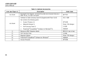
Optional Accessories Description Bushealth Test Adapter: connects the probe tip to busses that use a DB9, RJ-45, or a M12 connector Software & Cable Carrying Case Kit (Supplied with Fluke 12x/S) Set contains the following parts: • Screen Protector • Magnetic Hanger • Soft Carrying Case • FlukeView® ScopeMeter® Software for Windows® Banana-to-BNC Adapters (black) Soft Carrying Case Magnetic Hanger FlukeView...
Optional Accessories Description Bushealth Test Adapter: connects the probe tip to busses that use a DB9, RJ-45, or a M12 connector Software & Cable Carrying Case Kit (Supplied with Fluke 12x/S) Set contains the following parts: • Screen Protector • Magnetic Hanger • Soft Carrying Case • FlukeView® ScopeMeter® Software for Windows® Banana-to-BNC Adapters (black) Soft Carrying Case Magnetic Hanger FlukeView...
User Manual
Page 78
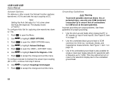
... potential. Grounding Guidelines XW Warning To prevent possible electrical shock, fire, or personal injury, use only one COM (common) connection ˜ or ensure that all connections to accept the change and exit the menu. 123B/124B/125B Users Manual Autoset Options On delivery or after a reset, the Autoset function captures waveforms ≥15 Hz and sets the input coupling to DC.
... potential. Grounding Guidelines XW Warning To prevent possible electrical shock, fire, or personal injury, use only one COM (common) connection ˜ or ensure that all connections to accept the change and exit the menu. 123B/124B/125B Users Manual Autoset Options On delivery or after a reset, the Autoset function captures waveforms ≥15 Hz and sets the input coupling to DC.


