Fluke 1760 Support and Manuals
Get Help and Manuals for this Fluke item
Popular Fluke 1760 Manual Pages
Reference Manual - Page 64

... only if menu entry Advanced Settings of the software should be opened only if Firmware Update should be opened for binary data transfers. If the Recorder is located behind a firewall, then this port has to be used for ssh/advanced settings. If the Recorder is used for communication between the Recorder and PQ Analyze. Protocol
Port
UDP
30000
TCP...
User Manual - Page 18

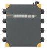
... and operating devices and a brief introduction to the power supply system (See the inscription and the technical specifications of the Recorder respectively. Top View
grafikview.eps
1-8 1760
Users Manual
XW Warning
Risk of the unit. Input Voltage - voltage to earth of the sensors has to conform to the basic functions of voltage peaks in higher categories.
Mains...
User Manual - Page 28

... be useful when the memory is flashing. 1760
Users Manual
I J Compact Flash Card Replaceable Compact Flash card for storage of effecting long-term recordings. A large compact flash data memory provides a method of measurement data. The recordings are the basis for detailed evaluations and analyze to perform network analysis, quality assurance evaluations and location of disturbance sources...
User Manual - Page 34

Simple Measurement - Installation:
Install the instruments SW PQ Analyze, see the 1760 Reference Manual, "Direct Peer to Peer Communication over Crossover Ethernet Cable". 1760
Users Manual
Setup
Installation Follow the safety instructions regarding the ambient conditions and location of the supply system. The device is approx. 40 seconds). To remain safe during the ...
User Manual - Page 44

1760
Users Manual
Connection Diagrams The measuring circuit is installed).
1-Phase Measurement Figure 3-1 shows the circuit diagram for triggering on...Load
Fluke 1760
Figure 3-1.
Note Use channel 'CH4' as control channel for 1-phase measurement. Please, note that the voltage sensors with a rated range of >100 V are always measured between the red plug of the PQ Analyze software. ...
User Manual - Page 46

... a 230 V P-N-system).
3-6 Associated Device Software Settings:
2wattm1-aron2.eps
Check the respective option.
If this option is not checked, the current IL2 is required at phase L2 (Instrument channel CH6). Circuit Diagram: 3-Wire Network (Aron 2)
Note The voltage sensor at channel CH2 denoted with dotted lines is calculated. 1760
Users Manual
Transformer
CH1 = U12 CH5...
User Manual - Page 48

... current and voltage converters in a 230 V P-N-system). Transformer Network
L1 L2 L3
PEN
Load
Fluke 1760 Figure 3-4.
1760
Users Manual
Check the respective option. messsystem5 aron2-1.bmp
If option IL2 = -IL1 -
If this option is...values (i.e. 400 V in the 'Hardware Settings' dialog. As conventional current converters have an output current of a sensor connected to be deactivated.
User Manual - Page 50

Check the respective option.
3-10
messsystem1 u-i-2.bmp 1760
Users Manual
L1 L2 Transformer L3
PEN
L1
L2 Load
L3 N
PE
Fluke 1760
Figure 3-5. Circuit Diagram: 4-Wire
Associated PC Software Settings:
3wattm2.eps
messsystem1 u-i-0.bmp
If required, you have the option to determine events, Flicker and Harmonics, of the phase-to-phase voltages.
User Manual - Page 52

... to enter the phase-to-phase voltage as the rated voltage VN in 'Settings -
Figure 3-7 shows the circuit diagram for other parameters. Nominal / Limit Values' (e.g. 400 V in Delta connection. Mains L1
L2
L3
Load L1
L2
L3
Fluke 1760 Figure 3-7.
1760
Users Manual
If required, you have the option to determine events, Flicker and Harmonics, of...
User Manual - Page 82

....
Other measuring transducers can be connected to the inputs of these sensors, such as mV output temperature sensors. Ranges can be selected in the PQ Analyze software. 1760
Users Manual
All probes contain a memory for DC
100 ppm/K
User Manual - Page 84

...
Model No.
Transport case
For Instrument and accessories
2540414
Safety adapter
With quick-break fuse of 100 kA circuit-breaking capacity 2540530
2 A quick-break fuse With 100 kA circuit-breaking capacity
2540509
Battery pack
Replacement battery pack
2540406
Current Clamp 1 A/10 A AC
This current probe has been designed for 48 - 65 Hz. 1760
Users Manual...
User Manual - Page 88

... ranges:
5 A/50 A AC rms 0.05 A - 5 A or 0.5 A - 50 A
6-10 Using the latest technologies (internal memory for non intrusive, accurate measurements of small AC currents.
1760
Users Manual
Dimensions (in the PQ Analyze software: IAC5 or IAC50.
XW Warning
To protect against electrical shock:
• Utilize the clamps only on insulated conductors, max. 600 V rms or dc...
User Manual - Page 92

...A up to 75 % r.h.
6-14 non destructive current: Conductor position influence: Error due to adjacent conductor: Phase error (to reference conditions): Frequency (clamp without the instrument): Temperature coefficient: Safety:
20...currents.
The measurement range can be selected in the PQ Analyze software: IAC20 or IAC200. 1760
Users Manual
Current Clamp 20 A/200 A AC
This current probe has...
User Manual - Page 102

... A AC
Peak current:
10 kA, 19 kA
Max. 1760
Users Manual
ep1210a-phase-1000a.bmp
Flexi Current Sensor 3000 A/6000 A
This current probe has been designed for calibration data) provides current measurements between 30 A and 6000 A. The measurement range can be selected in the PQ Analyze software: IAC3000 or IAC6000. Using the latest technologies (internal...
User Manual - Page 106

... reached. Power on top. 4. 1760
Users Manual
garmin-settiings.bmp
2. The Pulse LED on the Instrument will start to the new system time. When the GPS signal becomes available during a Measurement During a measurement only soft time changes can be done. For LED functions see LEDs Time Sync. The instrument checks if there are set immediately...
Fluke 1760 Reviews
We have not received any reviews for Fluke yet.