
User Manual
Page 4
279 FC Users Manual Temperature Units 11 Image Memory Management 12 Calibration 12 Device Information 12 Inputs 13 Rotary Switch and Pushbuttons 13 IR Camera Mode 16 Basic Measurements ... AC Current Measurements 23 Diode Test 25 Frequency Measurements 27 Measurement Features 29 MIN MAX AVG Record Mode 29 Display Hold 30 Auto Range and Manual Range 31 AC Zero Input Behavior of True-rms Meters 31 SmartView® Software 32 Firmware Updates 32 IR Image Management 33 ii
279 FC Users Manual Temperature Units 11 Image Memory Management 12 Calibration 12 Device Information 12 Inputs 13 Rotary Switch and Pushbuttons 13 IR Camera Mode 16 Basic Measurements ... AC Current Measurements 23 Diode Test 25 Frequency Measurements 27 Measurement Features 29 MIN MAX AVG Record Mode 29 Display Hold 30 Auto Range and Manual Range 31 AC Zero Input Behavior of True-rms Meters 31 SmartView® Software 32 Firmware Updates 32 IR Image Management 33 ii

User Manual
Page 6
279 FC Users Manual iv
279 FC Users Manual iv

User Manual
Page 8
279 FC Users Manual vi
279 FC Users Manual vi

User Manual
Page 10
279 FC Users Manual viii
279 FC Users Manual viii

User Manual
Page 12
279 FC Users Manual How to the Product or the equipment under test. To register your product, visit http://register.fluke.com. To view, print, or download the latest manual supplement, visit http://us.fluke.com/usen/support/manuals. Use personal protective equipment (approved rubber gloves, face protection, and flameresistant clothes) to prevent shock and arc blast injury where...
279 FC Users Manual How to the Product or the equipment under test. To register your product, visit http://register.fluke.com. To view, print, or download the latest manual supplement, visit http://us.fluke.com/usen/support/manuals. Use personal protective equipment (approved rubber gloves, face protection, and flameresistant clothes) to prevent shock and arc blast injury where...

User Manual
Page 14
... Symbol Description Symbol Description W WARNING. HAZARDOUS VOLTAGE. This product complies with the solid waste stream. Contact your authorized Fluke Service Center for recycling information. The affixed label indicates that you must not discard this product as category 9 "Monitoring... the distribution part of the building's low-voltage MAINS installation. This product contains a Lithium-ion battery. 279 FC Users Manual Symbols used on the Product and in this product is applicable to European Union directives. RISK OF DANGER. Battery ...
... Symbol Description Symbol Description W WARNING. HAZARDOUS VOLTAGE. This product complies with the solid waste stream. Contact your authorized Fluke Service Center for recycling information. The affixed label indicates that you must not discard this product as category 9 "Monitoring... the distribution part of the building's low-voltage MAINS installation. This product contains a Lithium-ion battery. 279 FC Users Manual Symbols used on the Product and in this product is applicable to European Union directives. RISK OF DANGER. Battery ...

User Manual
Page 16
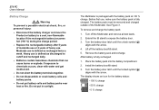
... Multimeter. Before You Start This section is measured. 6 To send an IR Camera image to the Fluke Connect App and in the list of connected Fluke tools, select 279 FC. You can now take, save, and share measurements with the app. Go to www.flukeconnect.com for... more information about how to Settings > Bluetooth. When HOLD is turned on. 4. Verify that Bluetooth is turned on the display. 3. On your smartphone, go to use the app. 279 FC Users Manual...
... Multimeter. Before You Start This section is measured. 6 To send an IR Camera image to the Fluke Connect App and in the list of connected Fluke tools, select 279 FC. You can now take, save, and share measurements with the app. Go to www.flukeconnect.com for... more information about how to Settings > Bluetooth. When HOLD is turned on. 4. Verify that Bluetooth is turned on the display. 3. On your smartphone, go to use the app. 279 FC Users Manual...
User Manual
Page 18
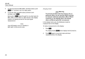
Do not put battery cells and battery packs near heat or fire. 279 FC Users Manual Battery Charge XW Warning To prevent a possible electrical shock, fire, or personal injury: • Disconnect the battery charger and move the Product or battery to ...
Do not put battery cells and battery packs near heat or fire. 279 FC Users Manual Battery Charge XW Warning To prevent a possible electrical shock, fire, or personal injury: • Disconnect the battery charger and move the Product or battery to ...
User Manual
Page 20
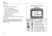
... Menu Go back to previous menu Move the menu highlight up Move the menu highlight down Accept a change to control actions within the Setup Menu. 279 FC Users Manual Setup Menu The Setup Menu includes these functions: • on/off for the audible beeper • on/off for automatic backlight dimming • on/off...
... Menu Go back to previous menu Move the menu highlight up Move the menu highlight down Accept a change to control actions within the Setup Menu. 279 FC Users Manual Setup Menu The Setup Menu includes these functions: • on/off for the audible beeper • on/off for automatic backlight dimming • on/off...

User Manual
Page 22
... exit the submenu with no changes. 12 Push to 100 images. Or, you can continue to save up to highlight Image Memory. 3. 279 FC Users Manual Image Memory Management You can go to the Setup Menu to delete all images: 1. Calibration For information about your Multimeter, see the...
... exit the submenu with no changes. 12 Push to 100 images. Or, you can continue to save up to highlight Image Memory. 3. 279 FC Users Manual Image Memory Management You can go to the Setup Menu to delete all images: 1. Calibration For information about your Multimeter, see the...
User Manual
Page 24
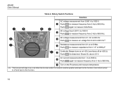
.... Push again to measure frequency from 0.1 Ω to 600 mV. Push for diode test. Shows OL above 2.0 V. AC current measurements from 1 nF to 2500 A. 279 FC Users Manual Table 4. Push to measure capacitance from 1 A to 9999 μF. 7 Continuity. Push again to measure Volts/Hertz. 5 6 DC voltage from 2 Hz to 1000 V. Rotary...
.... Push again to measure frequency from 0.1 Ω to 600 mV. Push for diode test. Shows OL above 2.0 V. AC current measurements from 1 nF to 2500 A. 279 FC Users Manual Table 4. Push to measure capacitance from 1 A to 9999 μF. 7 Continuity. Push again to measure Volts/Hertz. 5 6 DC voltage from 2 Hz to 1000 V. Rotary...

User Manual
Page 26
...61512; to protect the camera lens. to wait a minimum of 10 minutes if the most accurate temperature measurements and best image quality. 279 FC Users Manual IR Camera Mode XW Warning To prevent personal injury, see emissivity information for the temperature measurement. See Setup Menu on page 10 for ...display shows a center point marker for actual temperatures. A temperature scale is very important to the mobile app. See Set Up for Fluke Connect App on right edge of measurement are fully warmed up time for more information about how to connect to your use magnets near...
...61512; to protect the camera lens. to wait a minimum of 10 minutes if the most accurate temperature measurements and best image quality. 279 FC Users Manual IR Camera Mode XW Warning To prevent personal injury, see emissivity information for the temperature measurement. See Setup Menu on page 10 for ...display shows a center point marker for actual temperatures. A temperature scale is very important to the mobile app. See Set Up for Fluke Connect App on right edge of measurement are fully warmed up time for more information about how to connect to your use magnets near...
User Manual
Page 28
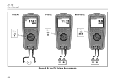
279 FC Users Manual VVooltlstsAACC VVooltlstsDDCC MMiilllilvivooltlstsDDCC iFlex iFlex iFlex Figure 4. AC and DC Voltage Measurements 18
279 FC Users Manual VVooltlstsAACC VVooltlstsDDCC MMiilllilvivooltlstsDDCC iFlex iFlex iFlex Figure 4. AC and DC Voltage Measurements 18
User Manual
Page 30
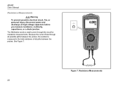
See Figure 7. Resistance Measurements 20 Figure 7. The Multimeter sends a small current through iFlex all possible paths between the probes. 279 FC Users Manual Resistance Measurements XW Warning To prevent possible electrical shock, fire, or personal injury, disconnect power and discharge all paths between the probes, the resistance measured is the total resistance of all high-voltage capacitors before you measure resistance, continuity, capacitance, or a diode junction. Because the current flows through the circuit for resistance measurements.
See Figure 7. Resistance Measurements 20 Figure 7. The Multimeter sends a small current through iFlex all possible paths between the probes. 279 FC Users Manual Resistance Measurements XW Warning To prevent possible electrical shock, fire, or personal injury, disconnect power and discharge all paths between the probes, the resistance measured is the total resistance of all high-voltage capacitors before you measure resistance, continuity, capacitance, or a diode junction. Because the current flows through the circuit for resistance measurements.
User Manual
Page 32
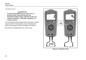
279 FC Users Manual Continuity Test XW Warning To prevent possible electrical shock, fire, or personal injury, disconnect power and discharge all high-voltage capacitors before you do continuity tests without the necessity to look at the display. The beeper lets you measure resistance, continuity, capacitance, or a diode junction. Continuity Tests 22 See Figure 9. iFlex iFlex OL shows on the display when the circuit is sensed. Figure 9. The continuity test uses a beeper that sounds when a closed circuit is open.
279 FC Users Manual Continuity Test XW Warning To prevent possible electrical shock, fire, or personal injury, disconnect power and discharge all high-voltage capacitors before you do continuity tests without the necessity to look at the display. The beeper lets you measure resistance, continuity, capacitance, or a diode junction. Continuity Tests 22 See Figure 9. iFlex iFlex OL shows on the display when the circuit is sensed. Figure 9. The continuity test uses a beeper that sounds when a closed circuit is open.
User Manual
Page 36
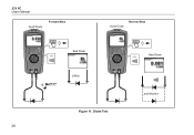
Diode Test 26 anadndShSohrteodrted 279 FC Users Manual GooooddDDioidoede Forward Bias GGoooodd DDiiooddee RReveevresresBeiaBsias BBaadd DDiiooddee iFlex BaaddDDioidoede 1 BBEEEEPP OPOEPNEN Figure 11.
Diode Test 26 anadndShSohrteodrted 279 FC Users Manual GooooddDDioidoede Forward Bias GGoooodd DDiiooddee RReveevresresBeiaBsias BBaadd DDiiooddee iFlex BaaddDDioidoede 1 BBEEEEPP OPOEPNEN Figure 11.
User Manual
Page 40
... live input signal measurement. The display shows when display hold a measurement on , the display does not change when a different potential is measured. Push . 279 FC Users Manual 5. When no label shows in MIN MAX AVG record mode. When HOLD is turned on the display: 1.
... live input signal measurement. The display shows when display hold a measurement on , the display does not change when a different potential is measured. Push . 279 FC Users Manual 5. When no label shows in MIN MAX AVG record mode. When HOLD is turned on the display: 1.

User Manual
Page 42
...® on your PC and the small (USB "Micro B") connector to download the firmware file. 4. Connect a USB 2.0 (High Speed) cable to http://www.fluke.com/downloads/smartview. 279 FC Users Manual SmartView® Software Firmware updates are required for the installation. SmartView recognizes the connection with the Multimeter. When the download is complete, click Setup...
...® on your PC and the small (USB "Micro B") connector to download the firmware file. 4. Connect a USB 2.0 (High Speed) cable to http://www.fluke.com/downloads/smartview. 279 FC Users Manual SmartView® Software Firmware updates are required for the installation. SmartView recognizes the connection with the Multimeter. When the download is complete, click Setup...
User Manual
Page 44
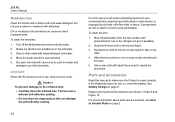
...each terminal with pressurized air can damage the anti-reflective coating. 34 For lens care you need a cleansing liquid such as this manual to Contact Fluke on page 8. If the Multimeter does not turn on dry cloth. 4. Move the swab around in one circular motion and discard ...make sure the Product is used correctly. Soak the lint-free cloth in the terminals. 3. Shake out dirt that can cause incorrect measurements. 279 FC Users Manual Multimeter Care Clean the holster with weak detergent and water. 4. Use a new cloth with alcohol, ethyl alcohol, or isopropyl alcohol and a...
...each terminal with pressurized air can damage the anti-reflective coating. 34 For lens care you need a cleansing liquid such as this manual to Contact Fluke on page 8. If the Multimeter does not turn on dry cloth. 4. Move the swab around in one circular motion and discard ...make sure the Product is used correctly. Soak the lint-free cloth in the terminals. 3. Shake out dirt that can cause incorrect measurements. 279 FC Users Manual Multimeter Care Clean the holster with weak detergent and water. 4. Use a new cloth with alcohol, ethyl alcohol, or isopropyl alcohol and a...

User Manual
Page 46
Accessories and Replacement Parts 279 FC Users Manual 11 10 36 1 9 2 8 4 5 3 6 7 Figure 13.
Accessories and Replacement Parts 279 FC Users Manual 11 10 36 1 9 2 8 4 5 3 6 7 Figure 13.


