User Manual
Page 1
All product names are subject to change without notice. Specifications are trademarks of their respective companies. All rights reserved. Ti200, Ti300, Ti400 Thermal Imagers Users Manual PN 4281773 September 2013 © 2013 Fluke Corporation.
All product names are subject to change without notice. Specifications are trademarks of their respective companies. All rights reserved. Ti200, Ti300, Ti400 Thermal Imagers Users Manual PN 4281773 September 2013 © 2013 Fluke Corporation.

User Manual
Page 7
All Imagers display thermal images on mobile devices. SmartView® Mobile software is also available for use in many useful features and functions associated with IR-Fusion® technology with ... LCD touch screen and can be transferred through the memory card to a PC, a direct USB connection to the PC, or by wireless transfer to the Imager. Introduction The Fluke Ti200, Ti300, and Ti400 Thermal Imagers (the Product or Imager) are handheld, infrared imaging cameras for quality analysis and reporting.
All Imagers display thermal images on mobile devices. SmartView® Mobile software is also available for use in many useful features and functions associated with IR-Fusion® technology with ... LCD touch screen and can be transferred through the memory card to a PC, a direct USB connection to the PC, or by wireless transfer to the Imager. Introduction The Fluke Ti200, Ti300, and Ti400 Thermal Imagers (the Product or Imager) are handheld, infrared imaging cameras for quality analysis and reporting.

User Manual
Page 9
..., WA USA www.patentlabel.com/fluke Figure 1. Lens Cover Laser Warning hie05.eps Warning To prevent personal injury: • Read all safety information before you use the Product. • Carefully ... the Product if it operates incorrectly. • Do not use the Product if it is on the inside of the Product lens cover, see Figure 1. Thermal Imagers Safety Information Additional laser warning information is damaged. 3
..., WA USA www.patentlabel.com/fluke Figure 1. Lens Cover Laser Warning hie05.eps Warning To prevent personal injury: • Read all safety information before you use the Product. • Carefully ... the Product if it operates incorrectly. • Do not use the Product if it is on the inside of the Product lens cover, see Figure 1. Thermal Imagers Safety Information Additional laser warning information is damaged. 3

User Manual
Page 11
... the flexibility and allow more applications for information about how to access digital copies of the accessories available for instructions on how to install a lens. 5 Thermal Imagers Radio Frequency Data Radio Frequency Data See page 39 for the Imager. Accessories Table 2 is a list of the radio licenses on the...
... the flexibility and allow more applications for information about how to access digital copies of the accessories available for instructions on how to install a lens. 5 Thermal Imagers Radio Frequency Data Radio Frequency Data See page 39 for the Imager. Accessories Table 2 is a list of the radio licenses on the...
User Manual
Page 13
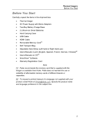
...8226; Users Manuals on CD[2] • SmartView® Software • Warranty Registration Card Note [1] Fluke recommends the memory card that is supplied with your product, email Fluke at TPubs@fluke.com. Thermal Imagers Before You Start Before You Start Carefully unpack the items in the shipment box: •...; Thermal Imager • AC Power Supply with Mains Adapters • Two-Bay Battery Charge Base ...
...8226; Users Manuals on CD[2] • SmartView® Software • Warranty Registration Card Note [1] Fluke recommends the memory card that is supplied with your product, email Fluke at TPubs@fluke.com. Thermal Imagers Before You Start Before You Start Carefully unpack the items in the shipment box: •...; Thermal Imager • AC Power Supply with Mains Adapters • Two-Bay Battery Charge Base ...

User Manual
Page 15
...charge is removed. See the charging temperature specification. If you remove the Imager from the charger before you charge in the center of the display when the Imager is connected to the charger. Thermal Imagers Before You Start On-Imager AC Power Socket 1. Connect the ac power adapter into an AC wall... outlet and connect the dc output to show that the Imager is fully charged. Keep the Imager attached to ac power or ...
...charge is removed. See the charging temperature specification. If you remove the Imager from the charger before you charge in the center of the display when the Imager is connected to the charger. Thermal Imagers Before You Start On-Imager AC Power Socket 1. Connect the ac power adapter into an AC wall... outlet and connect the dc output to show that the Imager is fully charged. Keep the Imager attached to ac power or ...
User Manual
Page 16
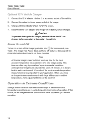
... Connect the 12 V adapter into the 12 V accessory socket of operation. Ti200, Ti300, Ti400 Users Manual Optional 12 V Vehicle Charger 1. Power On and Off To turn on the screen. 4. Note All thermal imagers need sufficient warm-up ) before you start or jump start the vehicle. Operation in... Extreme Conditions Storage and/or continual operation of the Imager in extreme ambient temperature conditions can result in ambient temperature, more ...
... Connect the 12 V adapter into the 12 V accessory socket of operation. Ti200, Ti300, Ti400 Users Manual Optional 12 V Vehicle Charger 1. Power On and Off To turn on the screen. 4. Note All thermal imagers need sufficient warm-up ) before you start or jump start the vehicle. Operation in... Extreme Conditions Storage and/or continual operation of the Imager in extreme ambient temperature conditions can result in ambient temperature, more ...

User Manual
Page 17
Thermal Imagers Features and Controls Features and Controls Table 3 shows the Imager features and controls. Features and Controls 3 2 4 5 Ti200 IR FUSION TECHNOLOGY 1 6 11 12 7 8 10 9 13 Item Description HDMI Connection USB Cable Connection Microphone Speaker LCD Display Power On/Off Function Buttons (F1, F2, and F3) Arrow Buttons Lithium-ion Smart Battery hie01.eps 11 Table 3.
Thermal Imagers Features and Controls Features and Controls Table 3 shows the Imager features and controls. Features and Controls 3 2 4 5 Ti200 IR FUSION TECHNOLOGY 1 6 11 12 7 8 10 9 13 Item Description HDMI Connection USB Cable Connection Microphone Speaker LCD Display Power On/Off Function Buttons (F1, F2, and F3) Arrow Buttons Lithium-ion Smart Battery hie01.eps 11 Table 3.

User Manual
Page 19
...standard trigger position for a pistol-grip device. Correct focus makes sure that the infrared energy is located in proper focus. 13 Thermal Imagers Primary and Secondary Triggers Primary and Secondary Triggers The two-part trigger is correctly directed onto the pixels of the detector. The ...Focus System and laser pointer. See page 32 for possible storage to memory by the user. The LaserSharp Auto Focus System, only from Fluke, uses a precisionadjusted and aligned laser pointer to enable and disable the LaserSharp™ Auto Focus System. Aim the laser pointer at ...
...standard trigger position for a pistol-grip device. Correct focus makes sure that the infrared energy is located in proper focus. 13 Thermal Imagers Primary and Secondary Triggers Primary and Secondary Triggers The two-part trigger is correctly directed onto the pixels of the detector. The ...Focus System and laser pointer. See page 32 for possible storage to memory by the user. The LaserSharp Auto Focus System, only from Fluke, uses a precisionadjusted and aligned laser pointer to enable and disable the LaserSharp™ Auto Focus System. Aim the laser pointer at ...

User Manual
Page 21
...buffer and you can choose to save the image or pull the primary trigger again or to cancel and return to cycle through the secondary menus. Thermal Imagers How to Use the Menus How to save or edit the image. The primary menu shows five secondary menus ...for date, time, language, units, file format, and Imager information. The primary, secondary, and option menus close 10...
...buffer and you can choose to save the image or pull the primary trigger again or to cancel and return to cycle through the secondary menus. Thermal Imagers How to Use the Menus How to save or edit the image. The primary menu shows five secondary menus ...for date, time, language, units, file format, and Imager information. The primary, secondary, and option menus close 10...

User Manual
Page 23
... to a Voice Annotation (Recording) The voice (audio) recording replays through the speaker. Push when done. 6. Push again to see the image on page 34 to pause the audio. 17 Push to record up to save the audio with the... to collate multiple files at a later time. Voice annotation is only available in the .is2 file format and is stored in the Review Image Files section on the display. 2. Thermal Imagers Image Capture i Voice Annotation (Recording) To add a voice (audio) recording: 1. Push / to the audio. 5. Push to listen...
... to a Voice Annotation (Recording) The voice (audio) recording replays through the speaker. Push when done. 6. Push again to see the image on page 34 to pause the audio. 17 Push to record up to save the audio with the... to collate multiple files at a later time. Voice annotation is only available in the .is2 file format and is stored in the Review Image Files section on the display. 2. Thermal Imagers Image Capture i Voice Annotation (Recording) To add a voice (audio) recording: 1. Push / to the audio. 5. Push to listen...

User Manual
Page 25
Carefully pull the card out of the card and then release. See Figure 3. For information about how to view or erase a stored image, see page 18. Figure 3. The Micro SD memory card comes with an SD adapter for insertion into a PC or multi-function card reader if desired. ... page 34. 19 Push the card in on the exposed edge of the slot. The card should pop partially out after you release it catches. Thermal Imagers Micro SD Memory Card Micro SD Memory Card To eject a Micro SD memory card, push in until it . To use the Micro SD memory card...
Carefully pull the card out of the card and then release. See Figure 3. For information about how to view or erase a stored image, see page 18. Figure 3. The Micro SD memory card comes with an SD adapter for insertion into a PC or multi-function card reader if desired. ... page 34. 19 Push the card in on the exposed edge of the slot. The card should pop partially out after you release it catches. Thermal Imagers Micro SD Memory Card Micro SD Memory Card To eject a Micro SD memory card, push in until it . To use the Micro SD memory card...

User Manual
Page 27
...or the full automatic range. 3. Use / to adjust the span setting. Use / to adjust the level setting. Thermal Imagers Menus Menus The menus, together with the three function buttons and arrow buttons, are set for automatic or manual adjustment. Range Preset measurement ... and Manual ranging or Set Level/Span. 3. Push / to Measurement > Set Level/Span. 2. Push to the thermal images. Measurement Menu The Measurement Menu has settings for more information about the minimum span. 21 In manual mode the Set Level/Span control is ...
...or the full automatic range. 3. Use / to adjust the span setting. Use / to adjust the level setting. Thermal Imagers Menus Menus The menus, together with the three function buttons and arrow buttons, are set for automatic or manual adjustment. Range Preset measurement ... and Manual ranging or Set Level/Span. 3. Push / to Measurement > Set Level/Span. 2. Push to the thermal images. Measurement Menu The Measurement Menu has settings for more information about the minimum span. 21 In manual mode the Set Level/Span control is ...

User Manual
Page 29
... span. Push to increase or widen the temperature span. 2. Level and Span Settings hie07.eps Temperature Span for the Imager to adjust the level and span. Emissivity of a surface can , but not always, allow you adjust the manual span, the...effect on the apparent temperatures that the Imager observes. Understanding the emissivity of the display shows the thermal span increasing or decreasing in a temperature range within the total range. While you to obtain more accurate temperature measurements. 23 Level Thermal Imagers Menus Total Imager Range Span Figure 4.
... span. Push to increase or widen the temperature span. 2. Level and Span Settings hie07.eps Temperature Span for the Imager to adjust the level and span. Emissivity of a surface can , but not always, allow you adjust the manual span, the...effect on the apparent temperatures that the Imager observes. Understanding the emissivity of the display shows the thermal span increasing or decreasing in a temperature range within the total range. While you to obtain more accurate temperature measurements. 23 Level Thermal Imagers Menus Total Imager Range Span Figure 4.

User Manual
Page 31
.... Transmission/Transmittance Adjustment When you can make the temperature measurement better in many situations. To adjust the transmission percentage: 1. Thermal Imagers Menus Background (Reflected Background Temperature Compensation) Compensation for reflected background temperature is set in the window. Note If the Display ... Very hot objects or very cold objects can make the accuracy of the transmission correction can adjust this percentage in the Imager or in the SmartView® software. Note If Display Information is set to Display All, you see Emissivity Adjustment....
.... Transmission/Transmittance Adjustment When you can make the temperature measurement better in many situations. To adjust the transmission percentage: 1. Thermal Imagers Menus Background (Reflected Background Temperature Compensation) Compensation for reflected background temperature is set in the window. Note If the Display ... Very hot objects or very cold objects can make the accuracy of the transmission correction can adjust this percentage in the Imager or in the SmartView® software. Note If Display Information is set to Display All, you see Emissivity Adjustment....

User Manual
Page 33
...enabled: 1. Push / to set the new value. Push to highlight ON or OFF. 3. Thermal Imagers Menus Center Box The Center Box feature is adjusted to the thermal scene within the Center Box. Push to reduce the size of the Center Box. Push / to... increase the size of the Imager is an adjustable temperature measurement zone (box) that area. Push to ...
...enabled: 1. Push / to set the new value. Push to highlight ON or OFF. 3. Thermal Imagers Menus Center Box The Center Box feature is adjusted to the thermal scene within the Center Box. Push to reduce the size of the Center Box. Push / to... increase the size of the Imager is an adjustable temperature measurement zone (box) that area. Push to ...

User Manual
Page 35
....is2 file format. Saturation Colors is an option that you can be , and then allows you use of an aligned visible image and infrared image. IR-Fusion® Technology IR-Fusion® technology makes it to show you precisely where a potential problem might be customized ...: 1. Go to highlight the palette color. 3. Push to set the new option. 29 Push / to Measurement > Image > IR-Fusion. 2. Thermal Imagers Menus To switch between palettes: 1. Go to highlight an option. 3. Push to set the new palette color. Push / ...
....is2 file format. Saturation Colors is an option that you can be , and then allows you use of an aligned visible image and infrared image. IR-Fusion® Technology IR-Fusion® technology makes it to show you precisely where a potential problem might be customized ...: 1. Go to highlight the palette color. 3. Push to set the new option. 29 Push / to Measurement > Image > IR-Fusion. 2. Thermal Imagers Menus To switch between palettes: 1. Go to highlight an option. 3. Push to set the new palette color. Push / ...

User Manual
Page 37
... to the live view. To set . Push / to Image > Display. 2. Logo A Fluke logo shows on or turn on the display and captured images. Push to highlight on or off. 3. Thermal Imagers Menus Outside/Inside Alarm If you set values for the high-temperature color alarm and... a low-temperature color alarm, the Imager will have ON/OFF ...
... to the live view. To set . Push / to Image > Display. 2. Logo A Fluke logo shows on or turn on the display and captured images. Push to highlight on or off. 3. Thermal Imagers Menus Outside/Inside Alarm If you set values for the high-temperature color alarm and... a low-temperature color alarm, the Imager will have ON/OFF ...

User Manual
Page 39
Go to low, medium, and high. To set the backlight: 1. Thermal Imagers Menus Backlight The backlight level control is set to Camera > Backlight. 2. Push / to Camera > Torch. 2. Go to highlight high, medium, or low. 3. Push to set a new value. Push to toggle the torch between on and off. 33 Torch The torch illuminates darker work areas. To set : 1.
Go to low, medium, and high. To set the backlight: 1. Thermal Imagers Menus Backlight The backlight level control is set to Camera > Backlight. 2. Push / to Camera > Torch. 2. Go to highlight high, medium, or low. 3. Push to set a new value. Push to toggle the torch between on and off. 33 Torch The torch illuminates darker work areas. To set : 1.

User Manual
Page 41
...jpg, and .is2. This menu also has a section that displays information about the Imager such as units of temperature measurement, file format of all data into one location. 35 Thermal Imagers Menus Settings Menu The Settings menu has adjustments for analysis and modification in the included ...SmartView software. To change the temperature units: 1. Image format selections are more flexible for user preferences such as ...
...jpg, and .is2. This menu also has a section that displays information about the Imager such as units of temperature measurement, file format of all data into one location. 35 Thermal Imagers Menus Settings Menu The Settings menu has adjustments for analysis and modification in the included ...SmartView software. To change the temperature units: 1. Image format selections are more flexible for user preferences such as ...


