
English Manual.
Page 6
... Install the Memory 10 Install an Expansion Card 12 Install other Internal Connectors 13 Jumpers 17 Chapter 3 BIOS Setup Enter BIOS Setup 19 Main Menu 19 System Information 21 Advanced BIOS Features 23 Fox Central Control Unit 25 Advanced Chipset Features 29 Integrated Peripherals 33 Power Management Setup 38... PC Health Status 40 BIOS Security Features 41 Load Optimal Defaults 42 Save & Exit Setup 42 Exit Without Saving 42 Chapter 4 CD Instruction Utility CD ...
... Install the Memory 10 Install an Expansion Card 12 Install other Internal Connectors 13 Jumpers 17 Chapter 3 BIOS Setup Enter BIOS Setup 19 Main Menu 19 System Information 21 Advanced BIOS Features 23 Fox Central Control Unit 25 Advanced Chipset Features 29 Integrated Peripherals 33 Power Management Setup 38... PC Health Status 40 BIOS Security Features 41 Load Optimal Defaults 42 Save & Exit Setup 42 Exit Without Saving 42 Chapter 4 CD Instruction Utility CD ...
English Manual.
Page 7
... 65 FOX LOGO 66 FOX DMI 67 Chapter 5 RAID Configuration RAID Configuration Introduction 70 FastBuild Driver 72 Create a RAID Driver Diskette 74 RAID Enable in BIOS 76 Select a RAID Array for Use 76 Install a New Windows XP 89 Setting Up a Non-Bootable RAID Array 93 Technical Support : Support Website : http://www...
... 65 FOX LOGO 66 FOX DMI 67 Chapter 5 RAID Configuration RAID Configuration Introduction 70 FastBuild Driver 72 Create a RAID Driver Diskette 74 RAID Enable in BIOS 76 Select a RAID Array for Use 76 Install a New Windows XP 89 Setting Up a Non-Bootable RAID Array 93 Technical Support : Support Website : http://www...

English Manual.
Page 17
When memory is installed, the BIOS will automatically check the memory in only one direction. If you begin to insert the memory, switch the direction. Two DDR3 memory sockets are divided ...
When memory is installed, the BIOS will automatically check the memory in only one direction. If you begin to insert the memory, switch the direction. Two DDR3 memory sockets are divided ...
English Manual.
Page 19
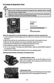
...unplug the power cord from the chassis back panel. 2. Make sure the metal contacts on your operating system. If necessary, go to BIOS Setup to the chassis back panel with the expansion card in your computer. Make sure the graphics card is fully seated in the ...expansion slot. 1. Secure the card's metal bracket to make any required BIOS changes for your card. Install the driver provided with a screw. 5. Installing and Removing a PCI Express x16 Graphics Card : • Installing a Graphics...
...unplug the power cord from the chassis back panel. 2. Make sure the metal contacts on your operating system. If necessary, go to BIOS Setup to the chassis back panel with the expansion card in your computer. Make sure the graphics card is fully seated in the ...expansion slot. 1. Secure the card's metal bracket to make any required BIOS changes for your card. Install the driver provided with a screw. 5. Installing and Removing a PCI Express x16 Graphics Card : • Installing a Graphics...

English Manual.
Page 23
SPKJ 1 EMPTY 2 NC 3 SPKJ 4 SPEAKER Fan Connectors : CPU_FAN, SYS_FAN There are two main fan headers on this motherboard. These fans can be automatically turned off after the system enters S3, S4 and S5 sleeping states. 1 GND POWER SENSE CONTROL CPU_FAN/SYS_FAN 16 The fan speed can be controlled and monitored in "PC Health Status" section of the chassis. 2 Speaker Connector : SPEAKER The speaker connector is used to connect speaker of the BIOS Setup.
SPKJ 1 EMPTY 2 NC 3 SPKJ 4 SPEAKER Fan Connectors : CPU_FAN, SYS_FAN There are two main fan headers on this motherboard. These fans can be automatically turned off after the system enters S3, S4 and S5 sleeping states. 1 GND POWER SENSE CONTROL CPU_FAN/SYS_FAN 16 The fan speed can be controlled and monitored in "PC Health Status" section of the chassis. 2 Speaker Connector : SPEAKER The speaker connector is used to connect speaker of the BIOS Setup.
English Manual.
Page 24
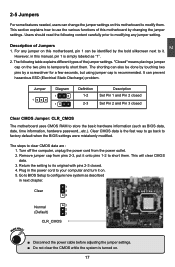
... cord from pins 2-3, put it onto pins 1-2 to it on. 5. Go to BIOS Setup to clear CMOS data are : 1. The following content carefully prior to factory default when the BIOS settings were mistakenly modified. It can also be identified by changing the jumper settings. The...CLR_CMOS ■ Disconnect the power cable before adjusting the jumper settings. ■ Do not clear the CMOS while the system is simply labeled as BIOS data, date, time information, hardware password...etc.). This section explains how to your computer and turn it . Description of the jumper settings. Plug...
... cord from pins 2-3, put it onto pins 1-2 to it on. 5. Go to BIOS Setup to clear CMOS data are : 1. The following content carefully prior to factory default when the BIOS settings were mistakenly modified. It can also be identified by changing the jumper settings. The...CLR_CMOS ■ Disconnect the power cable before adjusting the jumper settings. ■ Do not clear the CMOS while the system is simply labeled as BIOS data, date, time information, hardware password...etc.). This section explains how to your computer and turn it . Description of the jumper settings. Plug...

English Manual.
Page 25
...Optimal Defaults ■ Save & Exit Setup ■ Exit Without Saving Since BIOS could be updated some other times, the BIOS information described in the future. You want to change system settings through the BIOS Setup menus. An error message appears on the screen during the system Power On...reference only. Detailed descriptions of this manual will remain consistent with the newly released BIOS at any given time in this manual is available. We do not guarantee the content of the BIOS parameters are also provided. This chapter includes the following cases occur: 1. This chapter...
...Optimal Defaults ■ Save & Exit Setup ■ Exit Without Saving Since BIOS could be updated some other times, the BIOS information described in the future. You want to change system settings through the BIOS Setup menus. An error message appears on the screen during the system Power On...reference only. Detailed descriptions of this manual will remain consistent with the newly released BIOS at any given time in this manual is available. We do not guarantee the content of the BIOS parameters are also provided. This chapter includes the following cases occur: 1. This chapter...

English Manual.
Page 26
... devices... We do not suggest that you change you can be viewed or set up through this menu. ► Advanced BIOS Features The advanced system features can press key to enter SETUP. ! Display System Information... Copyright (C) 1985-2006, American Megatrends..., Inc. ► System Information ► PC Health Status ► Advanced BIOS Features ► BIOS Security Features ► Fox Central Control Unit Load Optimal Defaults ► Advanced Chipset Features Save & Exit Setup ► ...
... devices... We do not suggest that you change you can be viewed or set up through this menu. ► Advanced BIOS Features The advanced system features can press key to enter SETUP. ! Display System Information... Copyright (C) 1985-2006, American Megatrends..., Inc. ► System Information ► PC Health Status ► Advanced BIOS Features ► BIOS Security Features ► Fox Central Control Unit Load Optimal Defaults ► Advanced Chipset Features Save & Exit Setup ► ...

English Manual.
Page 27
...such as less I/O cards, less memory ...etc.), still, it may sometimes come out an unstable system. It means, if your system loading is to adjust BIOS setting one by one, trial and error, to find out the best setting for your current system. ► Save & Exit Setup Save setting values to... CMOS and exit. ► Exit Without Saving Do not change Fan speeds, and displays temperatures and voltages of your CPU/System. ► BIOS Security Features The Supervisor/User password can be set to read/change anything and exit the setup. 20 What you have more memory or I/O cards...
...such as less I/O cards, less memory ...etc.), still, it may sometimes come out an unstable system. It means, if your system loading is to adjust BIOS setting one by one, trial and error, to find out the best setting for your current system. ► Save & Exit Setup Save setting values to... CMOS and exit. ► Exit Without Saving Do not change Fan speeds, and displays temperatures and voltages of your CPU/System. ► BIOS Security Features The Supervisor/User password can be set to read/change anything and exit the setup. 20 What you have more memory or I/O cards...

English Manual.
Page 28
...] configure system Date. ► Third IDE Slave [Not Detected] Halt On [All Errors But ...] Keyboard [Disabled] Mouse [Disabled] 3 Model Name :A74ML 3 Series BIOS ID :9A5F1D04 CPU Name :AMD Engineering Sample System Memory Size :512MB Move Enter:Select +/-/:Value F10:Save ESC:Exit F1:General Help F9:Optimized Defaults...will stop for a keyboard error if you to configure the desired time. to Sat., this item. 21 Year-year, set up the standard BIOS features, such as the date, time, floppy drive and so on. Use [ENTER] to enter the setting, then use the or keys ...
...] configure system Date. ► Third IDE Slave [Not Detected] Halt On [All Errors But ...] Keyboard [Disabled] Mouse [Disabled] 3 Model Name :A74ML 3 Series BIOS ID :9A5F1D04 CPU Name :AMD Engineering Sample System Memory Size :512MB Move Enter:Select +/-/:Value F10:Save ESC:Exit F1:General Help F9:Optimized Defaults...will stop for a keyboard error if you to configure the desired time. to Sat., this item. 21 Year-year, set up the standard BIOS features, such as the date, time, floppy drive and so on. Use [ENTER] to enter the setting, then use the or keys ...

English Manual.
Page 29
3 ► Mouse The system boot will not stop for a mouse error if you enabled this item. ► Model Name Model name of this information and discuss with the field service people if a BIOS upgrade is depending on how many memory modules were installed in your system before powering on. ► MAC Address This item shows the onboard LAN MAC address. 22 The size is needed. ► CPU Name It displays the current CPU name. ► System Memory Size This item displays the current memory size. User can check this product. ► BIOS ID It displays the current BIOS ID/version.
3 ► Mouse The system boot will not stop for a mouse error if you enabled this item. ► Model Name Model name of this information and discuss with the field service people if a BIOS upgrade is depending on how many memory modules were installed in your system before powering on. ► MAC Address This item shows the onboard LAN MAC address. 22 The size is needed. ► CPU Name It displays the current CPU name. ► System Memory Size This item displays the current memory size. User can check this product. ► BIOS ID It displays the current BIOS ID/version.

English Manual.
Page 30
Advanced BIOS Features CMOS Setup Utility - If the checking time is over . In addition, MPS 1.4 introduces support for MPS 1.4, you need to multiprocessor motherboards as 1.1 only if ... wait longer before another takes over the set value, the system will actually reduce performance as the default 1.4. Copyright (C) 1985-2006, American Megatrends, Inc. Advanced BIOS Features IDE Detect Time Out MPS Revision PCI Latency Timer Quiet Boot Quick Boot Bootup Num-Lock [35] Help Item [1.4] [64] Select the time out...
Advanced BIOS Features CMOS Setup Utility - If the checking time is over . In addition, MPS 1.4 introduces support for MPS 1.4, you need to multiprocessor motherboards as 1.1 only if ... wait longer before another takes over the set value, the system will actually reduce performance as the default 1.4. Copyright (C) 1985-2006, American Megatrends, Inc. Advanced BIOS Features IDE Detect Time Out MPS Revision PCI Latency Timer Quiet Boot Quick Boot Bootup Num-Lock [35] Help Item [1.4] [64] Select the time out...

English Manual.
Page 31
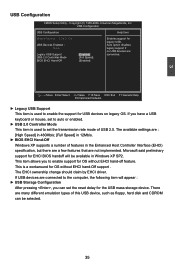
The available settings are: On (default) and Off. 24 3 [Disabled] : Displays the normal POST messages. [Enabled] : Displays OEM customer logo instead of POST messages. ► Quick Boot While Enabled, this option allows BIOS to skip certain tests while booting, this will shorten the time needed to boot the system. ► Bootup Num-Lock This item defines if the keyboard Num Lock key is active when your system is started.
The available settings are: On (default) and Off. 24 3 [Disabled] : Displays the normal POST messages. [Enabled] : Displays OEM customer logo instead of POST messages. ► Quick Boot While Enabled, this option allows BIOS to skip certain tests while booting, this will shorten the time needed to boot the system. ► Bootup Num-Lock This item defines if the keyboard Num Lock key is active when your system is started.

English Manual.
Page 32
...ESC:Exit F1:General Help F9:Optimized Defaults ► Smart Power LED Smart Power LED is a BIOS write-protection mechanism provided. Super BIOS Protect function protects your BIOS from virus attack, there is a feature built on your motherboard to its submenu. CIH. ►...Configuration Press to go to indicate different states during 25 Copyright (C) 1985-2006, American Megatrends, Inc. Fox Central Control Unit Super BIOS Protect ► Smart BIOS ► Fox Intelligent Stepping ► Voltage Options ► CPU Configuration [Disabled] Help Item [Press Enter] [Press Enter] ...
...ESC:Exit F1:General Help F9:Optimized Defaults ► Smart Power LED Smart Power LED is a BIOS write-protection mechanism provided. Super BIOS Protect function protects your BIOS from virus attack, there is a feature built on your motherboard to its submenu. CIH. ►...Configuration Press to go to indicate different states during 25 Copyright (C) 1985-2006, American Megatrends, Inc. Fox Central Control Unit Super BIOS Protect ► Smart BIOS ► Fox Intelligent Stepping ► Voltage Options ► CPU Configuration [Disabled] Help Item [Press Enter] [Press Enter] ...

English Manual.
Page 37
... cycles. Dual channel mode is freed for real world applications. Copyright (C) 1985-2006, American Megatrends, Inc. Memory Configuration CMOS Setup Utility - Enabling SurroundView in the BIOS enables the integrated UMA graphics controller, which addresses are used . ► Enable Clock to All DIMMs This setting is not supported.
... cycles. Dual channel mode is freed for real world applications. Copyright (C) 1985-2006, American Megatrends, Inc. Memory Configuration CMOS Setup Utility - Enabling SurroundView in the BIOS enables the integrated UMA graphics controller, which addresses are used . ► Enable Clock to All DIMMs This setting is not supported.
English Manual.
Page 38
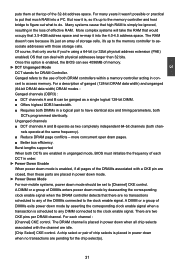
...; Better bus efficiency. Burst lengths supported When both DCTs are idle. [Chip Select] CKE control. There are no transactions are placed in unganged mode, BIOS must initialize the frequency of storage cells, it 's up to the memory controller to do. The RAM doesn't care because it's just an array of...loss of memory. ► DCT Unganged Mode DCT stands for the chip select(s). 31 A chip select or pair of chip selects is enabled, the BIOS can see 4096MB of effective RAM. Many systems cause that high RAM to simply be ignored, resulting in concert to the clock enable signal. A ...
...; Better bus efficiency. Burst lengths supported When both DCTs are idle. [Chip Select] CKE control. There are no transactions are placed in unganged mode, BIOS must initialize the frequency of storage cells, it 's up to the memory controller to do. The RAM doesn't care because it's just an array of...loss of memory. ► DCT Unganged Mode DCT stands for the chip select(s). 31 A chip select or pair of chip selects is enabled, the BIOS can see 4096MB of effective RAM. Many systems cause that high RAM to simply be ignored, resulting in concert to the clock enable signal. A ...

English Manual.
Page 39
.... If SPD value is selected. The Serial Presence Detect (SPD) device is manually selected according to enable/disable provision of each DCT in unganged mode, BIOS must initialize the frequency of DRAM timing by SPD device.
.... If SPD value is selected. The Serial Presence Detect (SPD) device is manually selected according to enable/disable provision of each DCT in unganged mode, BIOS must initialize the frequency of DRAM timing by SPD device.
English Manual.
Page 42
... are Legacy USB Support [Enabledd]] connected. USB Configuration USB Configuration Help Item Module Version - 2.24.3-13.4 Enables support for EHCI BIOS handoff will appear : ► USB Storage Configuration After pressing , you can be available in the Enhanced Host Controller Interface (EHCI)...without EHCI hand-Off support . The EHCI ownership change should claim by EHCI driver. USB 2.0 Controller Mode [Full Speed] BIOS EHCI Hand-Off [Enabled] Move Enter:Select +/-/:Value F10:Save ESC:Exit F1:General Help F9:Optimized Defaults ► ...
... are Legacy USB Support [Enabledd]] connected. USB Configuration USB Configuration Help Item Module Version - 2.24.3-13.4 Enables support for EHCI BIOS handoff will appear : ► USB Storage Configuration After pressing , you can be available in the Enhanced Host Controller Interface (EHCI)...without EHCI hand-Off support . The EHCI ownership change should claim by EHCI driver. USB 2.0 Controller Mode [Full Speed] BIOS EHCI Hand-Off [Enabled] Move Enter:Select +/-/:Value F10:Save ESC:Exit F1:General Help F9:Optimized Defaults ► ...

English Manual.
Page 43
... Trusted Computing Trusted Computing Help Item TCG/TPM Support [No] Enable/Disable TPM TCG (TPM 1.1/1.2) support in BIOS Move Enter:Select +/-/:Value F10:Save ESC:Exit F1:General Help F9:Optimized Defaults ► TCG/TPM Support ... Megatrends, Inc. SuperIO Configuration CMOS Setup Utility - SuperIO Configuration SuperIO Configuration Help Item Serial Port1 Address [3F8/TRQ4] Allows BIOS to Select Serial Port 1 Base Adress. 3 Move Enter:Select +/-/:Value F10:Save ESC:Exit F1:General Help F9:Optimized ...
... Trusted Computing Trusted Computing Help Item TCG/TPM Support [No] Enable/Disable TPM TCG (TPM 1.1/1.2) support in BIOS Move Enter:Select +/-/:Value F10:Save ESC:Exit F1:General Help F9:Optimized Defaults ► TCG/TPM Support ... Megatrends, Inc. SuperIO Configuration CMOS Setup Utility - SuperIO Configuration SuperIO Configuration Help Item Serial Port1 Address [3F8/TRQ4] Allows BIOS to Select Serial Port 1 Base Adress. 3 Move Enter:Select +/-/:Value F10:Save ESC:Exit F1:General Help F9:Optimized ...

English Manual.
Page 45
...) S5 - S3 - Software uses a different state value to distinguish between the S5 state and the S4 state to allow for initial boot operations within the BIOS to distinguish whether or not the boot is similar to a minimum, it wakes. Power Management Setup CMOS Setup Utility - Power Management Setup ACPI Suspend Type...
...) S5 - S3 - Software uses a different state value to distinguish between the S5 state and the S4 state to allow for initial boot operations within the BIOS to distinguish whether or not the boot is similar to a minimum, it wakes. Power Management Setup CMOS Setup Utility - Power Management Setup ACPI Suspend Type...


