
English Manual.
Page 5
... that the DC power supply is overclocked. tors. ■ If there is a PCI Express x16 graphics card installed in serious damage to the internal connectors on the motherboard, make sure there are uncertain about any metal leads or connec- Incorrect con- Also, make sure their pinouts are matching with the motherboard circuit or its components. Normally it comes out as a motherboard, CPU or memory. ■ Ensure...
... that the DC power supply is overclocked. tors. ■ If there is a PCI Express x16 graphics card installed in serious damage to the internal connectors on the motherboard, make sure there are uncertain about any metal leads or connec- Incorrect con- Also, make sure their pinouts are matching with the motherboard circuit or its components. Normally it comes out as a motherboard, CPU or memory. ■ Ensure...

English Manual.
Page 9
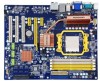
...;p�� Expansion Slots 1 x PCI Express x16 slot 2 x PCI Express x1 slots 3 x PCI slots Onboard Serial ATA 6 x SATA connectors 300MB/s data transfer rate Support hot plug and NCQ (Native Command Queuing ) USB Support hot plug Support up to 12 x USB 2.0 ports (6 rear panel ports, 3 onboard USB headers supporting 6 extra ports) Support USB 2.0 protocol up to 480Mb/s Internal Connectors 1 x 24-pin ATX main power connector 1 x 8-pin ATX 12V power connector 1 x Floppy disk drive connector 1 x IDE connector 6 x SATA connectors 3 x USB 2.0 c��...
...;p�� Expansion Slots 1 x PCI Express x16 slot 2 x PCI Express x1 slots 3 x PCI slots Onboard Serial ATA 6 x SATA connectors 300MB/s data transfer rate Support hot plug and NCQ (Native Command Queuing ) USB Support hot plug Support up to 12 x USB 2.0 ports (6 rear panel ports, 3 onboard USB headers supporting 6 extra ports) Support USB 2.0 protocol up to 480Mb/s Internal Connectors 1 x 24-pin ATX main power connector 1 x 8-pin ATX 12V power connector 1 x Floppy disk drive connector 1 x IDE connector 6 x SATA connectors 3 x USB 2.0 c��...

English Manual.
Page 14
... hardware installation process, including the installation of the CPU, memory, power supply, slots, pin headers and the mounting of these modules. Caution should be exercised during the installation of jumpers. This chapter includes the following information : ■ Install the CPU and CPU Cooler ■ Install the Memory ■ Install an Expansion Card ■ Install other Internal Connectors ■ Jumpers Please visit this chapter carefully. Please refer to the motherboard layout prior to any installation and...
... hardware installation process, including the installation of the CPU, memory, power supply, slots, pin headers and the mounting of these modules. Caution should be exercised during the installation of jumpers. This chapter includes the following information : ■ Install the CPU and CPU Cooler ■ Install the Memory ■ Install an Expansion Card ■ Install other Internal Connectors ■ Jumpers Please visit this chapter carefully. Please refer to the motherboard layout prior to any installation and...

English Manual.
Page 19
2 CAUTION 2-3 Install an Expansion Card ! ■ Make sure the motherboard supports the expansion card. Locate an expansion slot that came with a screw. 5. Remove the metal slot cover from the power outlet before installing an expansion card to prevent hardware damage. After installing all expansion cards, replace the chassis cover. 6. Installing and Removing a PCI Express x16 Graphics Card : • Installing a Graphics Card: Gently insert the graphics card into the slot. 4. If necessary, go to BIOS Setup to release the card and then pull...
2 CAUTION 2-3 Install an Expansion Card ! ■ Make sure the motherboard supports the expansion card. Locate an expansion slot that came with a screw. 5. Remove the metal slot cover from the power outlet before installing an expansion card to prevent hardware damage. After installing all expansion cards, replace the chassis cover. 6. Installing and Removing a PCI Express x16 Graphics Card : • Installing a Graphics Card: Gently insert the graphics card into the slot. 4. If necessary, go to BIOS Setup to release the card and then pull...
English Manual.
Page 21
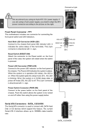
... panel switch and LED Indicators. This 2-pin connector is used to the Reset switch on the front panel of the chassis. PWR-LED - sign. Serial ATA Connectors : SATA_1/2/3/4/5/6 The Serial ATA connector is directional with +/- Reset Switch (RESET-SW) Attach the connector to connect with SATA Hard Disk or CD devices which support this switch allows the system to the power LED indicator on . When the system is in S3/S4 sleep state or power off rather than using an 8-pin ATX 12V power supply...
... panel switch and LED Indicators. This 2-pin connector is used to the Reset switch on the front panel of the chassis. PWR-LED - sign. Serial ATA Connectors : SATA_1/2/3/4/5/6 The Serial ATA connector is directional with +/- Reset Switch (RESET-SW) Attach the connector to connect with SATA Hard Disk or CD devices which support this switch allows the system to the power LED indicator on . When the system is in S3/S4 sleep state or power off rather than using an 8-pin ATX 12V power supply...

English Manual.
Page 24
... modified. Jumper 1 Diagram 1 1 Definition 1-2 2-3 Description Set Pin 1 and Pin 2 closed Set Pin 2 and Pin 3 closed . 4. Return the setting to its original with pins 2-3 closed Clear CMOS Jumper: CLR_CMOS The motherboard uses CMOS RAM to store the basic hardware information (such as BIOS data, date, time information, hardware password...etc.). Users should read the following table explains different types of the jumper settings. "Closed" means placing a jumper cap on the two pins to temporarily short them . Clear CMOS data...
... modified. Jumper 1 Diagram 1 1 Definition 1-2 2-3 Description Set Pin 1 and Pin 2 closed Set Pin 2 and Pin 3 closed . 4. Return the setting to its original with pins 2-3 closed Clear CMOS Jumper: CLR_CMOS The motherboard uses CMOS RAM to store the basic hardware information (such as BIOS data, date, time information, hardware password...etc.). Users should read the following table explains different types of the jumper settings. "Closed" means placing a jumper cap on the two pins to temporarily short them . Clear CMOS data...

English Manual.
Page 27
... set up through this menu. ► PC Health Status This setup enables you have more memory or I/O cards installed. It means, if your system loading is to adjust BIOS setting one by one, trial and error, to find out the best setting for your current system. ► Save & Exit Setup Save setting values to CMOS and exit. ► Exit Without Saving Do not change Fan speeds, and displays temperatures and voltages...
... set up through this menu. ► PC Health Status This setup enables you have more memory or I/O cards installed. It means, if your system loading is to adjust BIOS setting one by one, trial and error, to find out the best setting for your current system. ► Save & Exit Setup Save setting values to CMOS and exit. ► Exit Without Saving Do not change Fan speeds, and displays temperatures and voltages...

English Manual.
Page 28
... keys to select an item, then use [TAB] to 31. This item displays the drive information of IDE devices. Year-year, set up . [All Errors] : All errors can result in system halt. [All Errors But...] : All errors but keyboard or mouse or floppy can be enabled/disabled in system halt. The three fields of the setting are : : respectively. ► Primary / Secondary / Third / Fourth IDE Master / Slave While entering setup, BIOS...
... keys to select an item, then use [TAB] to 31. This item displays the drive information of IDE devices. Year-year, set up . [All Errors] : All errors can result in system halt. [All Errors But...] : All errors but keyboard or mouse or floppy can be enabled/disabled in system halt. The three fields of the setting are : : respectively. ► Primary / Secondary / Third / Fourth IDE Master / Slave While entering setup, BIOS...
English Manual.
Page 29
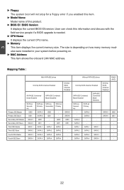
... current CPU name. ► Memory This item displays the current memory size. Without PATA IDE drives OnChip SATA Channel Enabled SATA IDE Combined Mode Enabled SATA as Secondary SATA 5 SATA 6 SATA 1 SATA 2 SATA as Primary Secondary Primary SATA 5 SATA 6 IDE0 IDE1 SATA 1 SATA 2 IDE0 IDE1 SATA 1 SATA 2 IDE0 IDE1 SATA 1 SATA 2 OnChip SATA Channel Disabled SATA 5 SATA 6 IDE0 IDE1 - 3 ► Floppy The system boot will not stop for a floppy error if you enabled this item. ► Model Name Model name of this information and discuss with the field service people if a BIOS upgrade...
... current CPU name. ► Memory This item displays the current memory size. Without PATA IDE drives OnChip SATA Channel Enabled SATA IDE Combined Mode Enabled SATA as Secondary SATA 5 SATA 6 SATA 1 SATA 2 SATA as Primary Secondary Primary SATA 5 SATA 6 IDE0 IDE1 SATA 1 SATA 2 IDE0 IDE1 SATA 1 SATA 2 IDE0 IDE1 SATA 1 SATA 2 OnChip SATA Channel Disabled SATA 5 SATA 6 IDE0 IDE1 - 3 ► Floppy The system boot will not stop for a floppy error if you enabled this item. ► Model Name Model name of this information and discuss with the field service people if a BIOS upgrade...
English Manual.
Page 34
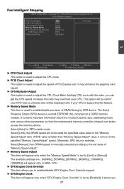
... the CPU clock. ► PCIE Clock Adjust This option is selected. It may overclock your CPU is supporting this feature. ► Memory Speed Mode This item is unlocked and will run at the specified "Memory Speed Adjust" speed. It contains important information about the module's speed, size, addressing mode and various other parameters, so that the motherboard memory controller (chipset) can get the CPU speed. Otherwise, SPD value is used to enable/disable provision of DRAM timing...
... the CPU clock. ► PCIE Clock Adjust This option is selected. It may overclock your CPU is supporting this feature. ► Memory Speed Mode This item is unlocked and will run at the specified "Memory Speed Adjust" speed. It contains important information about the module's speed, size, addressing mode and various other parameters, so that the motherboard memory controller (chipset) can get the CPU speed. Otherwise, SPD value is used to enable/disable provision of DRAM timing...

English Manual.
Page 41
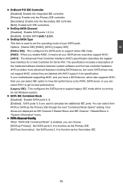
...; Help Item OnBoard PCI IDE Controller [Enabled] Disabled: Disable the �O�n�C�h�ip�S��AT�A��C�h�a�nn�e�l E�n�a�bl�e�d I �in the network board, you set up a diskless workstation on the network to be booted remotely. ► HD Audio Controller This item is used to enable or disable the onboard LAN boot optional ROM. Move Enter:Select...
...; Help Item OnBoard PCI IDE Controller [Enabled] Disabled: Disable the �O�n�C�h�ip�S��AT�A��C�h�a�nn�e�l E�n�a�bl�e�d I �in the network board, you set up a diskless workstation on the network to be booted remotely. ► HD Audio Controller This item is used to enable or disable the onboard LAN boot optional ROM. Move Enter:Select...
English Manual.
Page 42
...also support AHCI. [AHCI] - If your motherboard supporting AHCI, and you have fair performance (only PATA, SATA level), or you can select AHCI to get its specification. Four drives are displayed as IDE Channel 0 Master/Slave and IDE Channel 1 Master/Slave in its best performance. [Legacy IDE] - Options : [Native IDE]; [RAID]; [AHCI]; [Legacy IDE]. [Native IDE] - The Advanced Host Controller Interface (AHCI) specification describes the register level interface for a Host Controller for old Windows system. ► SATA IDE Combined Mode [Disabled] : Disable SATA ports 5, 6. [Enabled] : SATA...
...also support AHCI. [AHCI] - If your motherboard supporting AHCI, and you have fair performance (only PATA, SATA level), or you can select AHCI to get its specification. Four drives are displayed as IDE Channel 0 Master/Slave and IDE Channel 1 Master/Slave in its best performance. [Legacy IDE] - Options : [Native IDE]; [RAID]; [AHCI]; [Legacy IDE]. [Native IDE] - The Advanced Host Controller Interface (AHCI) specification describes the register level interface for a Host Controller for old Windows system. ► SATA IDE Combined Mode [Disabled] : Disable SATA ports 5, 6. [Enabled] : SATA...

English Manual.
Page 43
... a USB keyboard or mouse, set the transmission rate mode of features in the Enhanced Host Controller Interface (EHCI) specification, but there are a few features that are : [High Speed] in 480Mbps; [Full Speed] in 12Mbps. ► BIOS EHCI Hand-Off Windows XP supports a number of USB 2.0. IDE1 - The available settings are not implemented. 3 Primary IDE Master With PATA IDE drives OnChip SATA Channel Enabled OnChip SATA Channel Disabled SATA IDE Combined Mode Enabled SATA IDE Combined Mode Disabled SATA as Secondary IDE0 SATA as SATA...
... a USB keyboard or mouse, set the transmission rate mode of features in the Enhanced Host Controller Interface (EHCI) specification, but there are a few features that are : [High Speed] in 480Mbps; [Full Speed] in 12Mbps. ► BIOS EHCI Hand-Off Windows XP supports a number of USB 2.0. IDE1 - The available settings are not implemented. 3 Primary IDE Master With PATA IDE drives OnChip SATA Channel Enabled OnChip SATA Channel Disabled SATA IDE Combined Mode Enabled SATA IDE Combined Mode Disabled SATA as Secondary IDE0 SATA as SATA...
English Manual.
Page 47
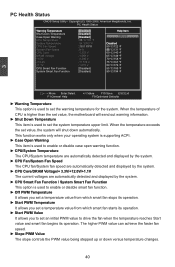
... Start value and smart fan begins its operation. PC Health Status CMOS Setup Utility - This function works only when your operating system is supporting ACPI. ► Case Open Warning This item is used to enable or disable case open warning function. ► CPU/System Temperature The CPU/System temperature are automatically detected and displayed by the system. ► CPU Fan/System Fan Speed The CPU fan/System fan speed are automatically detected and displayed by the system. ► CPU Core/DRAM Voltage...
... Start value and smart fan begins its operation. PC Health Status CMOS Setup Utility - This function works only when your operating system is supporting ACPI. ► Case Open Warning This item is used to enable or disable case open warning function. ► CPU/System Temperature The CPU/System temperature are automatically detected and displayed by the system. ► CPU Fan/System Fan Speed The CPU fan/System fan speed are automatically detected and displayed by the system. ► CPU Core/DRAM Voltage...

English Manual.
Page 51
.../DVD-ROM drive, and the main menu will be displayed on your PC screen to guide you to change your system without going to install. 1. AMD Chipset Driver B. Microsoft DirectX 9.0 F. FOX ONE B. FOX DMI E. Norton Internet Security I. 4 Utility CD content This motherboard comes with one Utility CD. AMD RAID Utility 44 Install Driver Use these options to install additional software programs. FOX ONE is set to install all the drivers have been installed. Software Utilities Use these options to [RAID]) 2. A. Realtek HDA Audio Driver C. Realtek 811X LAN Driver D. AMD RAID...
.../DVD-ROM drive, and the main menu will be displayed on your PC screen to guide you to change your system without going to install. 1. AMD Chipset Driver B. Microsoft DirectX 9.0 F. FOX ONE B. FOX DMI E. Norton Internet Security I. 4 Utility CD content This motherboard comes with one Utility CD. AMD RAID Utility 44 Install Driver Use these options to install additional software programs. FOX ONE is set to install all the drivers have been installed. Software Utilities Use these options to [RAID]) 2. A. Realtek HDA Audio Driver C. Realtek 811X LAN Driver D. AMD RAID...

English Manual.
Page 76
... setup program to select a RAID array for use . 3. A CD/DVD-ROM drive. 3. Existing Windows XP (or Vista) system with new RAID built as data storage. What kinds of hardware and software you need here : 1. A floppy drive. 2. Creating a Non-Bootable Array - Follow 5-4 to create a RAID driver diskette. 2. Several SATA hard disks. 4. A RAID driver diskette. 5. A CD/DVD-ROM drive. 2. Follow 5-3 to install AMD RAID driver into your existing Windows XP system, it is not bundled.) 6. Follow 5-2 to set RAID enabled in Control Panel to...
... setup program to select a RAID array for use . 3. A CD/DVD-ROM drive. 3. Existing Windows XP (or Vista) system with new RAID built as data storage. What kinds of hardware and software you need here : 1. A floppy drive. 2. Creating a Non-Bootable Array - Follow 5-4 to create a RAID driver diskette. 2. Several SATA hard disks. 4. A RAID driver diskette. 5. A CD/DVD-ROM drive. 2. Follow 5-3 to install AMD RAID driver into your existing Windows XP system, it is not bundled.) 6. Follow 5-2 to set RAID enabled in Control Panel to...

English Manual.
Page 83
5 5-2 RAID Enable in BIOS 1. Press to enter the main menu of FastBuild BIOS. PATA Channel Config [SATA as Primary]� Move Enter:Select +/-/:Value F10:Save ESC:Exit F1:General Help F9:Optimized Defaults 5-3 Select a RAID Array for hard drive or DVD connection. 4. Enter the BIOS setup by pressing key when boot up. 2. Enable RAID function and individual SATA port for Use When BIOS is restarted, it will display a message asking you to press [Ctrl-F] key to save the setting then PC...
5 5-2 RAID Enable in BIOS 1. Press to enter the main menu of FastBuild BIOS. PATA Channel Config [SATA as Primary]� Move Enter:Select +/-/:Value F10:Save ESC:Exit F1:General Help F9:Optimized Defaults 5-3 Select a RAID Array for hard drive or DVD connection. 4. Enter the BIOS setup by pressing key when boot up. 2. Enable RAID function and individual SATA port for Use When BIOS is restarted, it will display a message asking you to press [Ctrl-F] key to save the setting then PC...
English Manual.
Page 96
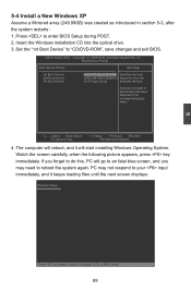
... next screen displays. Set the "1st Boot Device" to enter BIOS Setup during POST. 2. A device enclosed in parenthesis has been disabled in section 5-3, after the system restarts : 1. PC may need to do this, PC will start installing Windows Operating System. Watch the screen carefully, when the following picture appears, press key immediately. 5-4 Install a New Windows XP Assume a Mirrored array (249.99GB) was created as introduced in the corresponding type menu. CMOS Setup Utility...
... next screen displays. Set the "1st Boot Device" to enter BIOS Setup during POST. 2. A device enclosed in parenthesis has been disabled in section 5-3, after the system restarts : 1. PC may need to do this, PC will start installing Windows Operating System. Watch the screen carefully, when the following picture appears, press key immediately. 5-4 Install a New Windows XP Assume a Mirrored array (249.99GB) was created as introduced in the corresponding type menu. CMOS Setup Utility...

English Manual.
Page 97
... to continue the specific driver installation. Windows Setup Setup could not determine the type of one or more mass storage devices installed in your system, the following mass storage device(s): * To specify additional SCSI adapters, CD-ROM drivers, or special disk controllers for use with Windows, press ENTER. Press after it is done. Currently, Setup will ask you floppy drive. 5 5. Windows Setup Please insert the disk labeled manufacturer-supplied hardware support disk into you to manually specify an adapter...
... to continue the specific driver installation. Windows Setup Setup could not determine the type of one or more mass storage devices installed in your system, the following mass storage device(s): * To specify additional SCSI adapters, CD-ROM drivers, or special disk controllers for use with Windows, press ENTER. Press after it is done. Currently, Setup will ask you floppy drive. 5 5. Windows Setup Please insert the disk labeled manufacturer-supplied hardware support disk into you to manually specify an adapter...

English Manual.
Page 100
... the following setup : ■ Boot Disk with the same brand, size and model number. CMOS Setup Utility - Seagate ST3320620AS, (320.07GB) connected to SATA port3. ■ A SATA DVD Drive : A DVD drive connected to Master. ■ A Mirrored RAID Array Disk : Two SATA hard disks are configured as Primary] Move Enter:Select +/-/:Value F10:Save ESC:Exit F1:General Help F9:Optimized Defaults 93 OnChip SATA Type [RAID] Enable: Enable the SATA IDE Combined Mode [Enabled] IDE controller.
... the following setup : ■ Boot Disk with the same brand, size and model number. CMOS Setup Utility - Seagate ST3320620AS, (320.07GB) connected to SATA port3. ■ A SATA DVD Drive : A DVD drive connected to Master. ■ A Mirrored RAID Array Disk : Two SATA hard disks are configured as Primary] Move Enter:Select +/-/:Value F10:Save ESC:Exit F1:General Help F9:Optimized Defaults 93 OnChip SATA Type [RAID] Enable: Enable the SATA IDE Combined Mode [Enabled] IDE controller.


