
English Manual.
Page 12
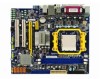
... In 5.1-channel Rear Speaker Out* Front Speaker Out Center/Subwoofer Out* * : Please refer to assign the audio output ports for USB devices such as monitor or LCD display. 6. 1 1-3 Back Panel Connectors PS/2 Mouse Port 1 Parallel Port 3 LAN Port 8 Line In Line Out Microphone 2 4 5 PS/2 Keyboard Port Serial Port VGA Port 6 USB Ports 7 Audio Ports 1. Serial Port This is output of 2/4/5.1 channels. Use this port for different applications of RS232 COM1 port. 5. VGA Port To connect with external display devices, such as an USB keyboard/mouse, USB printer, USB flash drive and...
... In 5.1-channel Rear Speaker Out* Front Speaker Out Center/Subwoofer Out* * : Please refer to assign the audio output ports for USB devices such as monitor or LCD display. 6. 1 1-3 Back Panel Connectors PS/2 Mouse Port 1 Parallel Port 3 LAN Port 8 Line In Line Out Microphone 2 4 5 PS/2 Keyboard Port Serial Port VGA Port 6 USB Ports 7 Audio Ports 1. Serial Port This is output of 2/4/5.1 channels. Use this port for different applications of RS232 COM1 port. 5. VGA Port To connect with external display devices, such as an USB keyboard/mouse, USB printer, USB flash drive and...
English Manual.
Page 19
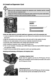
... read the manual that supports your computer. PCI Express x1 PCI Express x16 PCI Follow the steps below to prevent hardware damage. Secure the card's metal bracket to the chassis back panel with your expansion card. ■ Always turn off the computer and unplug the power cord from the chassis back panel. 2. Turn on your card. Installing and Removing a PCI Express x16 Graphics Card : • Installing a Graphics Card: Gently insert the graphics card into the slot. 4. Locate an expansion slot that...
... read the manual that supports your computer. PCI Express x1 PCI Express x16 PCI Follow the steps below to prevent hardware damage. Secure the card's metal bracket to the chassis back panel with your expansion card. ■ Always turn off the computer and unplug the power cord from the chassis back panel. 2. Turn on your card. Installing and Removing a PCI Express x16 Graphics Card : • Installing a Graphics Card: Gently insert the graphics card into the slot. 4. Locate an expansion slot that...

English Manual.
Page 21
... This motherboard includes one connector for connecting the front panel switch and LED Indicators. It indicates the active status of the chassis. This 2-pin connector is directional with SATA Hard Disk or CD devices which supporting this function, you should purchase additional device and install it. 14 1 + HDD-LED - 2 + PWR-LED - Reset Switch (RESET-SW) Attach the connector to be turned on the front panel of the case; sign. Power Switch Connector (PWR-SW) Connect to the power button on and off mode...
... This motherboard includes one connector for connecting the front panel switch and LED Indicators. It indicates the active status of the chassis. This 2-pin connector is directional with SATA Hard Disk or CD devices which supporting this function, you should purchase additional device and install it. 14 1 + HDD-LED - 2 + PWR-LED - Reset Switch (RESET-SW) Attach the connector to be turned on the front panel of the case; sign. Power Switch Connector (PWR-SW) Connect to the power button on and off mode...

English Manual.
Page 24
...! Jumper 1 Diagram 1 1 Definition 1-2 2-3 Description Set Pin 1 and Pin 2 closed Set Pin 2 and Pin 3 closed . 4. Turn off the computer, unplug the power cord from pins 2-3, put it on . 17 Clear CMOS data is turned on . 5. The steps to its original with pins 2-3 closed Clear CMOS Jumper: CLR_CMOS The motherboard uses CMOS RAM to factory default when the BIOS settings were mistakenly modified. However, in this motherboard by changing the jumper settings. Normal 1 2 (Default) 3 CLR_CMOS ■ Disconnect the power cable before adjusting the jumper settings...
...! Jumper 1 Diagram 1 1 Definition 1-2 2-3 Description Set Pin 1 and Pin 2 closed Set Pin 2 and Pin 3 closed . 4. Turn off the computer, unplug the power cord from pins 2-3, put it on . 17 Clear CMOS data is turned on . 5. The steps to its original with pins 2-3 closed Clear CMOS Jumper: CLR_CMOS The motherboard uses CMOS RAM to factory default when the BIOS settings were mistakenly modified. However, in this motherboard by changing the jumper settings. Normal 1 2 (Default) 3 CLR_CMOS ■ Disconnect the power cable before adjusting the jumper settings...
English Manual.
Page 39
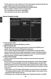
... processor (IGP) is automatically disabled, and the system memory allocated to ensure the most efficient use . 2. CMOS Setup Utility - Help Item Internal Graphics Mode UMA Frame Buffer Size Primary Video Controller Surround View [Enabled] Options [128MB] [PCI-GFXO-IGFX] Disabled [Disabled] Enabled 3 Move Enter:Select +/-/:Value F10:Save ESC:Exit F1:General Help F9:Optimized Defaults ► Internal Graphics Mode Enable/Disable the integrated UMA graphics controller. ► UMA Frame Buffer Size Allocates system memory for use as the primary boot...
... processor (IGP) is automatically disabled, and the system memory allocated to ensure the most efficient use . 2. CMOS Setup Utility - Help Item Internal Graphics Mode UMA Frame Buffer Size Primary Video Controller Surround View [Enabled] Options [128MB] [PCI-GFXO-IGFX] Disabled [Disabled] Enabled 3 Move Enter:Select +/-/:Value F10:Save ESC:Exit F1:General Help F9:Optimized Defaults ► Internal Graphics Mode Enable/Disable the integrated UMA graphics controller. ► UMA Frame Buffer Size Allocates system memory for use as the primary boot...

English Manual.
Page 41
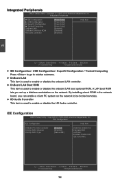
... OnBoard PCI IDE Controller [Enabled] Disabled: Disable the OnChip SATA Channel [Enabled] I integrated IDE OnChip SATA Type [Native IDE] controller. Enabled: Enable both IDE controllers. By installing a boot ROM in the network board, you set up a diskless workstation on the network to be booted remotely. ► HD Audio Controller This item is used to enable or disable the onboard LAN boot optional ROM. Integrated Peripherals CMOS Setup Utility - IDE Configuration CMOS Setup...
... OnBoard PCI IDE Controller [Enabled] Disabled: Disable the OnChip SATA Channel [Enabled] I integrated IDE OnChip SATA Type [Native IDE] controller. Enabled: Enable both IDE controllers. By installing a boot ROM in the network board, you set up a diskless workstation on the network to be booted remotely. ► HD Audio Controller This item is used to enable or disable the onboard LAN boot optional ROM. Integrated Peripherals CMOS Setup Utility - IDE Configuration CMOS Setup...

English Manual.
Page 42
... enable RAID, it means all your motherboard supporting AHCI, and you have fair performance (only PATA, SATA level), or you can select IDE option to have a SATA device, which is running for old Windows system. If your SATA drives must also support AHCI. [AHCI] - USB Configuration CMOS Setup Utility - USB Configuration USB Configuration Help Item USB Devices Enabled : Options 1 Drive Disabled OnBoard USB Controller [Enabled] Enabled USB 2.0 Controller [Enabled] USB 2.0 Controller Mode [High Speed] Legacy USB Support [Enabled...
... enable RAID, it means all your motherboard supporting AHCI, and you have fair performance (only PATA, SATA level), or you can select IDE option to have a SATA device, which is running for old Windows system. If your SATA drives must also support AHCI. [AHCI] - USB Configuration CMOS Setup Utility - USB Configuration USB Configuration Help Item USB Devices Enabled : Options 1 Drive Disabled OnBoard USB Controller [Enabled] Enabled USB 2.0 Controller [Enabled] USB 2.0 Controller Mode [High Speed] Legacy USB Support [Enabled...

English Manual.
Page 51
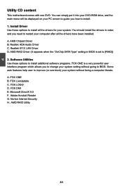
... drivers have been installed. FOX ONE B. Install Driver Use these options to install additional software programs. FOX ONE is set to install. 1. Realtek HDA Audio Driver C. FOX DMI E. AMD RAID Utility 44 AMD Chipset Driver B. Norton Internet Security H. 4 Utility CD content This motherboard comes with one DVD. Adobe Acrobat Reader G. Some auto features help user to BIOS. FOX LiveUpdate C. You can simply put it into your DVD-ROM drive, and the main menu will be displayed on your PC screen to guide...
... drivers have been installed. FOX ONE B. Install Driver Use these options to install additional software programs. FOX ONE is set to install. 1. Realtek HDA Audio Driver C. FOX DMI E. AMD RAID Utility 44 AMD Chipset Driver B. Norton Internet Security H. 4 Utility CD content This motherboard comes with one DVD. Adobe Acrobat Reader G. Some auto features help user to BIOS. FOX LiveUpdate C. You can simply put it into your DVD-ROM drive, and the main menu will be displayed on your PC screen to guide...
English Manual.
Page 76
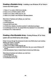
... : 1. Set RAID enabled in motherboard package.) 5. Follow 5-3 to Install a new Windows Operating System. Follow 5-4 to select a RAID array for use . 4. Windows XP or Vista Install CD. Follow 5-5 to go through the processes to select a RAID array for use . 3. Follow 5-3 to build a new RAID array in BIOS. 3. A DVD-ROM drive. 2. Existing Windows XP (or Vista) system with new RAID built as data storage. A motherboard driver CD. 69 Installing a new Windows XP (or Vista) in Control Panel to install AMD RAID driver...
... : 1. Set RAID enabled in motherboard package.) 5. Follow 5-3 to Install a new Windows Operating System. Follow 5-4 to select a RAID array for use . 4. Windows XP or Vista Install CD. Follow 5-5 to go through the processes to select a RAID array for use . 3. Follow 5-3 to build a new RAID array in BIOS. 3. A DVD-ROM drive. 2. Existing Windows XP (or Vista) system with new RAID built as data storage. A motherboard driver CD. 69 Installing a new Windows XP (or Vista) in Control Panel to install AMD RAID driver...

English Manual.
Page 83
... Enable in BIOS 1. Enter the BIOS setup by pressing key when boot up. 2. Press to enter the main menu of Option ROM Utility. Copyright (C) 1985-2008, American Megatrends, Inc. IDE Configuration IDE Configuration Help Item OnBoard PCI IDE Controller [Enabled] Options OnChip SATA Channel [Enabled] I OnChip SATA Type [RAID] Native IDE RAID AHCI Legacy IDE 5 Move Enter:Select +/-/:Value F10:Save ESC:Exit F1:General Help F9:Optimized Defaults 5-3 Select a RAID Array for hard drive or DVD connection. 4. CMOS...
... Enable in BIOS 1. Enter the BIOS setup by pressing key when boot up. 2. Press to enter the main menu of Option ROM Utility. Copyright (C) 1985-2008, American Megatrends, Inc. IDE Configuration IDE Configuration Help Item OnBoard PCI IDE Controller [Enabled] Options OnChip SATA Channel [Enabled] I OnChip SATA Type [RAID] Native IDE RAID AHCI Legacy IDE 5 Move Enter:Select +/-/:Value F10:Save ESC:Exit F1:General Help F9:Optimized Defaults 5-3 Select a RAID Array for hard drive or DVD connection. 4. CMOS...
English Manual.
Page 97
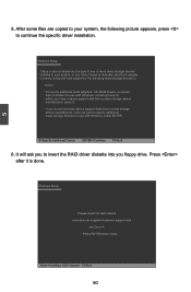
.... Windows Setup Setup could not determine the type of one or more mass storage devices installed in your system, the following mass storage device(s): * To specify additional SCSI adapters, CD-ROM drivers, or special disk controllers for which you have a device support disk from a mass storage device manufacturer, press S. * If you floppy drive. Windows Setup Please insert the disk labeled manufacturer-supplied hardware support disk into you do not want to insert the RAID driver diskette into Drive A: * Press ENTER...
.... Windows Setup Setup could not determine the type of one or more mass storage devices installed in your system, the following mass storage device(s): * To specify additional SCSI adapters, CD-ROM drivers, or special disk controllers for which you have a device support disk from a mass storage device manufacturer, press S. * If you floppy drive. Windows Setup Please insert the disk labeled manufacturer-supplied hardware support disk into you do not want to insert the RAID driver diskette into Drive A: * Press ENTER...

English Manual.
Page 100
... Array Disk : Two SATA hard disks are : Hitachi HDT725025VLA3, (250.05GB) connected to "IDE Configuration" menu. IDE Configuration IDE Configuration Help Item OnBoard PCI IDE Controller [Enabled] Options OnChip SATA Channel [Enabled] I OnChip SATA Type [RAID] Native IDE RAID AHCI Legacy IDE Move Enter:Select +/-/:Value F10:Save ESC:Exit F1:General Help F9:Optimized Defaults 93 5 5-5 Setting Up a Non-Bootable RAID Array This section assumes the following setup : ■ Boot Disk with the same brand, size...
... Array Disk : Two SATA hard disks are : Hitachi HDT725025VLA3, (250.05GB) connected to "IDE Configuration" menu. IDE Configuration IDE Configuration Help Item OnBoard PCI IDE Controller [Enabled] Options OnChip SATA Channel [Enabled] I OnChip SATA Type [RAID] Native IDE RAID AHCI Legacy IDE Move Enter:Select +/-/:Value F10:Save ESC:Exit F1:General Help F9:Optimized Defaults 93 5 5-5 Setting Up a Non-Bootable RAID Array This section assumes the following setup : ■ Boot Disk with the same brand, size...

English Manual.
Page 21
... motherboard includes one connector for connecting the front panel switch and LED Indicators. Hard Disk LED Connector (HDD-LED) Connect to connect with SATA Hard Disk or CD devices which supporting this feature. Reset Switch (RESET-SW) Attach the connector to the power LED indicator on the front panel of the case; When the system is in operation (S0 status), the LED is on the front panel of the chassis. Serial ATA Connectors : SATA_1/2/3/4 The Serial ATA connector is off rather than using the power supply button. To utilize...
... motherboard includes one connector for connecting the front panel switch and LED Indicators. Hard Disk LED Connector (HDD-LED) Connect to connect with SATA Hard Disk or CD devices which supporting this feature. Reset Switch (RESET-SW) Attach the connector to the power LED indicator on the front panel of the case; When the system is in operation (S0 status), the LED is on the front panel of the chassis. Serial ATA Connectors : SATA_1/2/3/4 The Serial ATA connector is off rather than using the power supply button. To utilize...

English Manual.
Page 24
... a jumper cap on . 5. Jumper 1 Diagram 1 1 Definition 1-2 2-3 Description Set Pin 1 and Pin 2 closed Set Pin 2 and Pin 3 closed . 4. Return the setting to its original with pins 2-3 closed Clear CMOS Jumper: CLR_CMOS The motherboard uses CMOS RAM to store the basic hardware information (such as described in the power cord to short them . Plug in next chapter. 1 Clear 2 3 WARNING! This will clear CMOS data. 3. Go to BIOS Setup to it on the two pins to factory default when the BIOS settings were...
... a jumper cap on . 5. Jumper 1 Diagram 1 1 Definition 1-2 2-3 Description Set Pin 1 and Pin 2 closed Set Pin 2 and Pin 3 closed . 4. Return the setting to its original with pins 2-3 closed Clear CMOS Jumper: CLR_CMOS The motherboard uses CMOS RAM to store the basic hardware information (such as described in the power cord to short them . Plug in next chapter. 1 Clear 2 3 WARNING! This will clear CMOS data. 3. Go to BIOS Setup to it on the two pins to factory default when the BIOS settings were...
English Manual.
Page 41
...ROM in the network board, you set up a diskless workstation on the network to be booted remotely. ► HD Audio Controller This item is used to enable or disable the onboard LAN boot optional ROM. Move Enter:Select +/-/:Value F10:Save ESC:Exit F1:General Help F9:Optimized Defaults 34 Enabled: Enable both IDE controllers. Copyright (C) 1985-2008, American Megatrends, Inc. A LAN boot ROM lets you can enable a client PC system on the network. IDE Configuration IDE Configuration Help Item OnBoard PCI IDE Controller [Enabled] Disabled...
...ROM in the network board, you set up a diskless workstation on the network to be booted remotely. ► HD Audio Controller This item is used to enable or disable the onboard LAN boot optional ROM. Move Enter:Select +/-/:Value F10:Save ESC:Exit F1:General Help F9:Optimized Defaults 34 Enabled: Enable both IDE controllers. Copyright (C) 1985-2008, American Megatrends, Inc. A LAN boot ROM lets you can enable a client PC system on the network. IDE Configuration IDE Configuration Help Item OnBoard PCI IDE Controller [Enabled] Disabled...

English Manual.
Page 42
...Help Item USB Devices Enabled : Options 1 Drive Disabled OnBoard USB Controller [Enabled] Enabled USB 2.0 Controller [Enabled] USB 2.0 Controller Mode [High Speed] Legacy USB Support [Enabled] ► USB Storage Configuration [Press Enter Move Enter:Select +/-/:Value F10:Save ESC:Exit F1:General Help F9:Optimized Defaults ► OnBoard USB Controller This item is used to enable or disable the onboard USB controller. ► USB 2.0 Controller This item is used to enable or disabled the enhanced host controller interface for Serial ATA...
...Help Item USB Devices Enabled : Options 1 Drive Disabled OnBoard USB Controller [Enabled] Enabled USB 2.0 Controller [Enabled] USB 2.0 Controller Mode [High Speed] Legacy USB Support [Enabled] ► USB Storage Configuration [Press Enter Move Enter:Select +/-/:Value F10:Save ESC:Exit F1:General Help F9:Optimized Defaults ► OnBoard USB Controller This item is used to enable or disable the onboard USB controller. ► USB 2.0 Controller This item is used to enable or disabled the enhanced host controller interface for Serial ATA...
English Manual.
Page 51
... G. Software Utilities Use these options to improve (or overclock) your computer after all the drivers for your system. Some auto features help user to install all the drivers have been installed. FOX ONE B. Install Driver Use these options to install additional software programs. FOX ONE is set to install. 1. You can simply put it into your DVD-ROM drive, and the main menu will be displayed on your PC screen to guide you to change your system setting without...
... G. Software Utilities Use these options to improve (or overclock) your computer after all the drivers for your system. Some auto features help user to install all the drivers have been installed. FOX ONE B. Install Driver Use these options to install additional software programs. FOX ONE is set to install. 1. You can simply put it into your DVD-ROM drive, and the main menu will be displayed on your PC screen to guide you to change your system setting without...

English Manual.
Page 83
... SATA port for Use When BIOS is restarted, it will reboot itself. 5-2 RAID Enable in BIOS 1. IDE Configuration IDE Configuration Help Item OnBoard PCI IDE Controller [Enabled] Options OnChip SATA Channel [Enabled] I OnChip SATA Type [RAID] Native IDE RAID AHCI Legacy IDE 5 Move Enter:Select +/-/:Value F10:Save ESC:Exit F1:General Help F9:Optimized Defaults 5-3 Select a RAID Array for hard drive or DVD connection. 4. Option ROM Utility (c) 2008 Advanced Micro Devices, Inc. [ Main Menu ] View Drive...
... SATA port for Use When BIOS is restarted, it will reboot itself. 5-2 RAID Enable in BIOS 1. IDE Configuration IDE Configuration Help Item OnBoard PCI IDE Controller [Enabled] Options OnChip SATA Channel [Enabled] I OnChip SATA Type [RAID] Native IDE RAID AHCI Legacy IDE 5 Move Enter:Select +/-/:Value F10:Save ESC:Exit F1:General Help F9:Optimized Defaults 5-3 Select a RAID Array for hard drive or DVD connection. 4. Option ROM Utility (c) 2008 Advanced Micro Devices, Inc. [ Main Menu ] View Drive...

English Manual.
Page 97
... mass storage devices for use with Windows, press ENTER. Currently, Setup will ask you floppy drive. Windows Setup Setup could not determine the type of one or more mass storage devices installed in your system, the following mass storage device(s): * To specify additional SCSI adapters, CD-ROM drivers, or special disk controllers for use with Windows, including those for which you have a device support disk from a mass storage device manufacturer, press S. * If you have any device support disks from a mass storage device manufacturer...
... mass storage devices for use with Windows, press ENTER. Currently, Setup will ask you floppy drive. Windows Setup Setup could not determine the type of one or more mass storage devices installed in your system, the following mass storage device(s): * To specify additional SCSI adapters, CD-ROM drivers, or special disk controllers for use with Windows, including those for which you have a device support disk from a mass storage device manufacturer, press S. * If you have any device support disks from a mass storage device manufacturer...

English Manual.
Page 100
...; A Mirrored RAID Array Disk : Two SATA hard disks are configured as a mirrored RAID1 array, they are using the hard disks with the same brand, size and model number. CMOS Setup Utility - Reboot your system, and go to save the settings and reboot. Seagate ST3320620AS, (320.07GB) connected to SATA port3. ■ A SATA DVD Drive : A DVD drive connected to SATA port1. 5 5-5 Setting Up a Non-Bootable RAID Array This section assumes the following setup : ■ Boot Disk with Windows XP installed : One hard disk HDS728090PLAT20...
...; A Mirrored RAID Array Disk : Two SATA hard disks are configured as a mirrored RAID1 array, they are using the hard disks with the same brand, size and model number. CMOS Setup Utility - Reboot your system, and go to save the settings and reboot. Seagate ST3320620AS, (320.07GB) connected to SATA port3. ■ A SATA DVD Drive : A DVD drive connected to SATA port1. 5 5-5 Setting Up a Non-Bootable RAID Array This section assumes the following setup : ■ Boot Disk with Windows XP installed : One hard disk HDS728090PLAT20...


