User Manual
Page 5
....aspx Memory, VGA Compatibility List: http://www.foxconnsupport.com/complist.aspx Please carefully read the following procedures to install your computer : ■ It is suggested to select high-quality, certified fans in serious damage to high temperature. Normal operation depends on the power, please make sure their pinouts are uncertain about any metal leads or connectors. ■ If there is a PCI Express x16 graphics card installed in...
....aspx Memory, VGA Compatibility List: http://www.foxconnsupport.com/complist.aspx Please carefully read the following procedures to install your computer : ■ It is suggested to select high-quality, certified fans in serious damage to high temperature. Normal operation depends on the power, please make sure their pinouts are uncertain about any metal leads or connectors. ■ If there is a PCI Express x16 graphics card installed in...
User Manual
Page 6
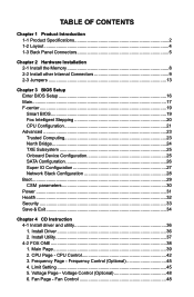
...Frequency Control (Optional 45 4. Fan Control 48 Install Driver 36 2. Voltage Page - Main Page 39 2. Table of Contents Chapter 1 Product Introduction 1-1 Product Specifications 2 1-2 Layout...4 1-3 Back Panel Connectors 5 Chapter 2 Hardware Installation 2-1 Install the Memory 8 2-2 Install other Internal Connectors 9 2-3 Jumpers 13 Chapter 3 BIOS Setup Enter BIOS Setup 16 Main...17 F-center...19 Smart BIOS 19 Fox Intelligent Stepping 20 CPU Configuration 21 Advanced...23 Trusted Computing 23 North Bridge 24 TXE Subsystem 25 Onboard Device Configuration 25 SATA...
...Frequency Control (Optional 45 4. Fan Control 48 Install Driver 36 2. Voltage Page - Main Page 39 2. Table of Contents Chapter 1 Product Introduction 1-1 Product Specifications 2 1-2 Layout...4 1-3 Back Panel Connectors 5 Chapter 2 Hardware Installation 2-1 Install the Memory 8 2-2 Install other Internal Connectors 9 2-3 Jumpers 13 Chapter 3 BIOS Setup Enter BIOS Setup 16 Main...17 F-center...19 Smart BIOS 19 Fox Intelligent Stepping 20 CPU Configuration 21 Advanced...23 Trusted Computing 23 North Bridge 24 TXE Subsystem 25 Onboard Device Configuration 25 SATA...
User Manual
Page 9
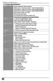
... PCI Express slot -Support PCI Express Gen2 5GT/s data rate Storage 2 x SATA 2.0 connectors (3Gb/s data transfer rate) LAN Realtek RTL8111F Gigabit LAN controller Support 10/100/1000Mbps Audio Realtek ALC662 -High Definition Audio -2/4/5.1-channel -Support Jack-Sensing function USB Support up to 8 x USB 2.0 ports (4 rear panel ports, 2 onboard USB headers supporting 4 extra ports) Support USB 2.0 protocol up to 480Mb/s Support up to 1 x USB 3.0 ports (1 rear panel ports) Support USB 3.0 protocol up to 5Gb/s Internal Connectors 1 x 24-Pin ATX power connector 1 x 4-pin ATX...
... PCI Express slot -Support PCI Express Gen2 5GT/s data rate Storage 2 x SATA 2.0 connectors (3Gb/s data transfer rate) LAN Realtek RTL8111F Gigabit LAN controller Support 10/100/1000Mbps Audio Realtek ALC662 -High Definition Audio -2/4/5.1-channel -Support Jack-Sensing function USB Support up to 8 x USB 2.0 ports (4 rear panel ports, 2 onboard USB headers supporting 4 extra ports) Support USB 2.0 protocol up to 480Mb/s Support up to 1 x USB 3.0 ports (1 rear panel ports) Support USB 3.0 protocol up to 5Gb/s Internal Connectors 1 x 24-Pin ATX power connector 1 x 4-pin ATX...
User Manual
Page 18
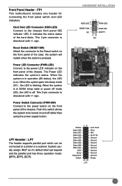
Front Panel Header : FP1 This motherboard includes one header for connecting the front panel switch and LED Indicators. This 2-pin connector is off rather than using the power supply button. sign. the system will restart when the switch is blinking; The Power LED indicates the system's status. When the system gets into sleep mode (S1) , the LED is pressed. Power LED Connector (PWR-LED) Connect to the power LED indicator on the front panel of the chassis. When the system...
Front Panel Header : FP1 This motherboard includes one header for connecting the front panel switch and LED Indicators. This 2-pin connector is off rather than using the power supply button. sign. the system will restart when the switch is blinking; The Power LED indicates the system's status. When the system gets into sleep mode (S1) , the LED is pressed. Power LED Connector (PWR-LED) Connect to the power LED indicator on the front panel of the chassis. When the system...
User Manual
Page 20
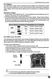
... how to modify them. Remove jumper cap from the power outlet. 2. Go to BIOS Setup to store the basic hardware information (such as described in this motherboard by changing the jumper settings. The shorting can prevent hazardous ESD (Electrical Static Discharge) problem. Return the setting to its original with pins 1-2 closed Clear CMOS Jumper: CLR_CMOS The motherboard uses CMOS RAM to configure new system as BIOS data, date, time information, hardware password...etc.).
... how to modify them. Remove jumper cap from the power outlet. 2. Go to BIOS Setup to store the basic hardware information (such as described in this motherboard by changing the jumper settings. The shorting can prevent hazardous ESD (Electrical Static Discharge) problem. Return the setting to its original with pins 1-2 closed Clear CMOS Jumper: CLR_CMOS The motherboard uses CMOS RAM to configure new system as BIOS data, date, time information, hardware password...etc.).
User Manual
Page 23
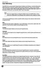
... setup enables you to read/change fan speeds, and displays temperatures and voltages of the screen, you have more memory or I /O cards, less memory ...etc.), still, it may sometimes come out an unstable system. Security The Administrator/User password can save or discard the changes and exit BIOS setup here. 16 You also can be set up through this menu. BIOS SETUP Enter BIOS Setup The BIOS is the communication bridge between hardware and software, correctly setting...
... setup enables you to read/change fan speeds, and displays temperatures and voltages of the screen, you have more memory or I /O cards, less memory ...etc.), still, it may sometimes come out an unstable system. Security The Administrator/User password can save or discard the changes and exit BIOS setup here. 16 You also can be set up through this menu. BIOS SETUP Enter BIOS Setup The BIOS is the communication bridge between hardware and software, correctly setting...
User Manual
Page 28
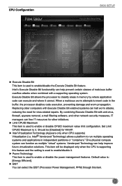
... with a supporting operating system. When a malicious worm attempts to enable or disable the power management features. Copyright (C) 2013 American Megatrends, Inc. ► Execute Disable Bit This item is used to 3. CPU Configuration BIOS SETUP Main F-center Advanced Boot CPU Configuration CPU Brand Name: Intel(R) Celeron(R) CPU J1900 @ 1.99GHz L1 Data Cache L1 Code Cache L2 Cache L3 Cache CPU Signature Max CPU Speed Min CPU Speed CPU Speed Processor Cores Intel HT Technology Intel VT-x Technology Intel SMX Technology Execute Disable Bit Limit...
... with a supporting operating system. When a malicious worm attempts to enable or disable the power management features. Copyright (C) 2013 American Megatrends, Inc. ► Execute Disable Bit This item is used to 3. CPU Configuration BIOS SETUP Main F-center Advanced Boot CPU Configuration CPU Brand Name: Intel(R) Celeron(R) CPU J1900 @ 1.99GHz L1 Data Cache L1 Code Cache L2 Cache L3 Cache CPU Signature Max CPU Speed Min CPU Speed CPU Speed Processor Cores Intel HT Technology Intel VT-x Technology Intel SMX Technology Execute Disable Bit Limit...

User Manual
Page 29
... report This item is used to enable or disable CPU C6 (ACPI C3) report to OS. ► Package C State limit It is used to dynamically adjust processor voltage and core frequency, which can result in decreased average power consumption and decreased average heat production. There are some system requirements must be met, including CPU, chipset, motherboard, BIOS and operation system. CAUTION BIOS SETUP Enhanced Intel SpeedStep®...
... report This item is used to enable or disable CPU C6 (ACPI C3) report to OS. ► Package C State limit It is used to dynamically adjust processor voltage and core frequency, which can result in decreased average power consumption and decreased average heat production. There are some system requirements must be met, including CPU, chipset, motherboard, BIOS and operation system. CAUTION BIOS SETUP Enhanced Intel SpeedStep®...

User Manual
Page 30
... Screen ↑ ↓/Click: Select Item Enter/Dbl Click: Select +/-: Change Opt. F1: General Help F2: Previous Values F3: Optimized Defaults F4: Save & Exit ESC/Right Click: Exit Version 2.16.1242. Advanced BIOS SETUP Main F-center Advanced Boot Power Health ▶ Trusted Computing ▶ North Bridge ▶ TXE Subsystem ▶ Onboard Device Configuration ▶ SATA Configuration ▶ Super IO Configuration ▶ Network Stack Configuration ▶ Realtek PCIe GBE Family Controller...
... Screen ↑ ↓/Click: Select Item Enter/Dbl Click: Select +/-: Change Opt. F1: General Help F2: Previous Values F3: Optimized Defaults F4: Save & Exit ESC/Right Click: Exit Version 2.16.1242. Advanced BIOS SETUP Main F-center Advanced Boot Power Health ▶ Trusted Computing ▶ North Bridge ▶ TXE Subsystem ▶ Onboard Device Configuration ▶ SATA Configuration ▶ Super IO Configuration ▶ Network Stack Configuration ▶ Realtek PCIe GBE Family Controller...
User Manual
Page 31
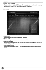
.... O.S. BIOS SETUP ► Security Device SUPPORT This item enables or disables BIOS support for security device. will not be available. North Bridge Main F-center Advanced Boot Power Health Security Save&Exit North Bridge Configuration Memory Information Total Memory Memory Slot0 Memory Configuration 1024 MB (DDR3/DDR3L 1333) 1024 MB (DDR3/DDR3L 1333) DVMT Pre-Allocated DVMT Total Gfx Mem [256M] [256MB] Select DVMT 5.0 PreAllocated (Fixed) Graphics Memory size used by the Internal Graphics Devices. →...
.... O.S. BIOS SETUP ► Security Device SUPPORT This item enables or disables BIOS support for security device. will not be available. North Bridge Main F-center Advanced Boot Power Health Security Save&Exit North Bridge Configuration Memory Information Total Memory Memory Slot0 Memory Configuration 1024 MB (DDR3/DDR3L 1333) 1024 MB (DDR3/DDR3L 1333) DVMT Pre-Allocated DVMT Total Gfx Mem [256M] [256MB] Select DVMT 5.0 PreAllocated (Fixed) Graphics Memory size used by the Internal Graphics Devices. →...
User Manual
Page 32
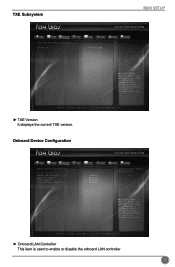
Onboard Device Configuration Main F-center Advanced Boot Power Health Security Save&Exit Onboard Device Configuration Onboard LAN Controller Onboard USB Controller Legacy USB Support USB3.0 Support Azalia HD Audio controller [Enabled] [Enabled] [Enabled] [Enabled] [Enabled] Enabled/Disabled Onboard LAN Controller. → ←: Select Screen ↑ ↓/Click: Select Item Enter/Dbl Click: Select +/-: Change Opt. TXE Subsystem BIOS SETUP Main F-center Advanced Boot Intel TXE Subsystem Configuration TXE Version Power Health 01.00.02.1060 Security Save&Exit ...
Onboard Device Configuration Main F-center Advanced Boot Power Health Security Save&Exit Onboard Device Configuration Onboard LAN Controller Onboard USB Controller Legacy USB Support USB3.0 Support Azalia HD Audio controller [Enabled] [Enabled] [Enabled] [Enabled] [Enabled] Enabled/Disabled Onboard LAN Controller. → ←: Select Screen ↑ ↓/Click: Select Item Enter/Dbl Click: Select +/-: Change Opt. TXE Subsystem BIOS SETUP Main F-center Advanced Boot Intel TXE Subsystem Configuration TXE Version Power Health 01.00.02.1060 Security Save&Exit ...

User Manual
Page 33
... AHCI to get its specification. This configures the SATA ports to enable or disable the Serial ATA Port 1/2. 26 If your SATA ports. [Native IDE] - BIOS SETUP ► Onboard USB Controller This item is used to enable or disable the onboard USB controller. ► Legacy USB Support This item is used to enable or disable the Azalia HD Audio Controller. SATA Configuration Main F-center Advanced Boot Power Health Security Save&Exit SATA Configuration Enable/Disable Serial ATA Onboard SATA Controller Onboard SATA Mode Serial-ATA Port 1 Serial-ATA Port 2 SATA Port0 Not Present SATA...
... AHCI to get its specification. This configures the SATA ports to enable or disable the Serial ATA Port 1/2. 26 If your SATA ports. [Native IDE] - BIOS SETUP ► Onboard USB Controller This item is used to enable or disable the onboard USB controller. ► Legacy USB Support This item is used to enable or disable the Azalia HD Audio Controller. SATA Configuration Main F-center Advanced Boot Power Health Security Save&Exit SATA Configuration Enable/Disable Serial ATA Onboard SATA Controller Onboard SATA Mode Serial-ATA Port 1 Serial-ATA Port 2 SATA Port0 Not Present SATA...
User Manual
Page 34
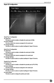
... enable or disable the parallel port (LPT/LPTE). ► Device Settings This item shows the resource assigned to the serial port. ► Change Settings This item is used to select an optimal settings for Super IO device. ► Device Mode This item is used to change the printer port mode. 27 Super IO Configuration BIOS SETUP Main F-center Advanced Boot Power Health Security Save&Exit Super IO Configuration Super IO Chip ▶ Serial Port 1 Configuration ▶ Serial Port 2 Configuration ▶ Parallel Port Configuration IT8728F Set...
... enable or disable the parallel port (LPT/LPTE). ► Device Settings This item shows the resource assigned to the serial port. ► Change Settings This item is used to select an optimal settings for Super IO device. ► Device Mode This item is used to change the printer port mode. 27 Super IO Configuration BIOS SETUP Main F-center Advanced Boot Power Health Security Save&Exit Super IO Configuration Super IO Chip ▶ Serial Port 1 Configuration ▶ Serial Port 2 Configuration ▶ Parallel Port Configuration IT8728F Set...
User Manual
Page 36
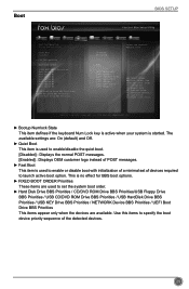
... settings are available. Boot BIOS SETUP Main F-center Advanced Boot Boot Configuration Bootup Numlock State Quiet Boot Fast Boot ▶ CSM Configuration Boot mode select FIXED BOOT ORDER Priorities Boot Option #1 Boot Option #2 Boot Option #3 Boot Option #4 Boot Option #5 Boot Option #6 Boot Option #7 ▶ USB HardDisk Drive BBS Priorities ▶ USB KEY Drive BBS Priorities ▶ UEFI Boot Drive BBS Prioriies Power Health [On] [Enabled] [Disabled] Security Save&Exit Select the keyboard NumLock state UEFI [UEFI Hard Disk] [UEFI CD/DVD...
... settings are available. Boot BIOS SETUP Main F-center Advanced Boot Boot Configuration Bootup Numlock State Quiet Boot Fast Boot ▶ CSM Configuration Boot mode select FIXED BOOT ORDER Priorities Boot Option #1 Boot Option #2 Boot Option #3 Boot Option #4 Boot Option #5 Boot Option #6 Boot Option #7 ▶ USB HardDisk Drive BBS Priorities ▶ USB KEY Drive BBS Priorities ▶ UEFI Boot Drive BBS Prioriies Power Health [On] [Enabled] [Disabled] Security Save&Exit Select the keyboard NumLock state UEFI [UEFI Hard Disk] [UEFI CD/DVD...
User Manual
Page 38
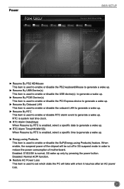
...(Days) When Resume by RTC is enabled, select a specific date to generate a wake up. ► RTC Alarm Time(HH:MM:SS) When Resume by pressing the power button. Power BIOS SETUP Main F-center Advanced Boot Power Health Security Save&Exit Resume By PS2 KB/Mouse Resume By USB Device(s) Resume By PCIE Device(s) Resume By Onboard LAN Resume By RTC Energy-using Products) feature. Copyright (C) 2013 American Megatrends...
...(Days) When Resume by RTC is enabled, select a specific date to generate a wake up. ► RTC Alarm Time(HH:MM:SS) When Resume by pressing the power button. Power BIOS SETUP Main F-center Advanced Boot Power Health Security Save&Exit Resume By PS2 KB/Mouse Resume By USB Device(s) Resume By PCIE Device(s) Resume By Onboard LAN Resume By RTC Energy-using Products) feature. Copyright (C) 2013 American Megatrends...
User Manual
Page 39
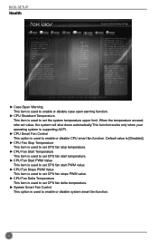
.... CPU Shutdowm Temperature CPU Smart Fan Control CPU Fan Stop Temperature CPU Fan Start Temperature CPU Fan Start PWM Value CPU Fan Slope PWM Value CPU Fan Delta Temperature System Smart Fan Control [Enabled] [Enabled] 0 35 120 3 2 [Disabled] → ←: Select Screen ↑ ↓/Click: Select Item Enter/Dbl Click: Select +/-: Change Opt. F1: General Help F2: Previous Values F3: Optimized Defaults F4: Save & Exit ESC/Right Click: Exit Version 2.16.1242. If don't enter bios setup and disabled Case Opening Warning one time, Instruction Alarm don't clear, it...
.... CPU Shutdowm Temperature CPU Smart Fan Control CPU Fan Stop Temperature CPU Fan Start Temperature CPU Fan Start PWM Value CPU Fan Slope PWM Value CPU Fan Delta Temperature System Smart Fan Control [Enabled] [Enabled] 0 35 120 3 2 [Disabled] → ←: Select Screen ↑ ↓/Click: Select Item Enter/Dbl Click: Select +/-: Change Opt. F1: General Help F2: Previous Values F3: Optimized Defaults F4: Save & Exit ESC/Right Click: Exit Version 2.16.1242. If don't enter bios setup and disabled Case Opening Warning one time, Instruction Alarm don't clear, it...
User Manual
Page 40
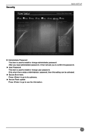
... a Administrator password, then this setting can be activated. ► Secure Boot menu Press to go to its submenu. ► Secure Flash update Press to go to install or change user password. Security BIOS SETUP Main F-center Advanced Boot Power Health Security Save&Exit Password Description Administrator Password User Password Administator Password ▶ Secure Boot menu ▶ Secure Flash update Not Installed Not Installed Set Administrator Password → ←: Select Screen ↑ ↓/Click: Select Item Enter/Dbl Click: Select +/-: Change Opt.
... a Administrator password, then this setting can be activated. ► Secure Boot menu Press to go to its submenu. ► Secure Flash update Press to go to install or change user password. Security BIOS SETUP Main F-center Advanced Boot Power Health Security Save&Exit Password Description Administrator Password User Password Administator Password ▶ Secure Boot menu ▶ Secure Flash update Not Installed Not Installed Set Administrator Password → ←: Select Screen ↑ ↓/Click: Select Item Enter/Dbl Click: Select +/-: Change Opt.
User Manual
Page 41
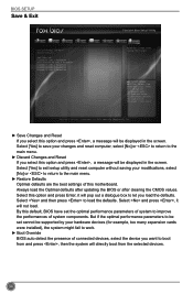
... return to work. ► Boot Override BIOS auto detect the presence of system components. Select and press , it will be supported by your hardware devices (for example, too many expansion cards were installed), the system might fail to the main menu. ► Restore Defaults Optimal defaults are the best settings of this option and press , a message will not load. Select [Yes] to exit setup utility and reset computer...
... return to work. ► Boot Override BIOS auto detect the presence of system components. Select and press , it will be supported by your hardware devices (for example, too many expansion cards were installed), the system might fail to the main menu. ► Restore Defaults Optimal defaults are the best settings of this option and press , a message will not load. Select [Yes] to exit setup utility and reset computer...
User Manual
Page 43
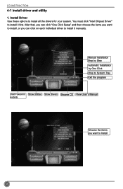
After that, you can click "One Click Setup" and then choose the items you can click on each individual driver to Install 36 Install Driver Use these options to install it manually. Manual Installation Step by Step Automatic Installation by One Click Drop to System Tray Exit the program Visit Foxconn's Show Utilities Show Drivers Browse CD View User's Manual website Choose the items you want to install, or you want to install it first. You must click "Intel Chipset Driver" to install all the drivers for your system. CD INSTRUCTION 4-1 Install driver and utility 1.
After that, you can click "One Click Setup" and then choose the items you can click on each individual driver to Install 36 Install Driver Use these options to install it manually. Manual Installation Step by Step Automatic Installation by One Click Drop to System Tray Exit the program Visit Foxconn's Show Utilities Show Drivers Browse CD View User's Manual website Choose the items you want to install, or you want to install it first. You must click "Intel Chipset Driver" to install all the drivers for your system. CD INSTRUCTION 4-1 Install driver and utility 1.
User Manual
Page 64
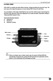
... boot Logo is a simple and useful utility to open it and change and delete the boot time Logo. Supporting Operating Systems Windows 8.1 ■ Windows 8 ■ Windows 7( 64-bit) Main screen Backup Change Exit Minimize About Website CAUTION When you enable the BIOS "Quiet Boot" setting in "Advanced BIOS Features" menu. During this time, please DO NOT shut down the application and the system, or the motherboard will be displayed if you change...
... boot Logo is a simple and useful utility to open it and change and delete the boot time Logo. Supporting Operating Systems Windows 8.1 ■ Windows 8 ■ Windows 7( 64-bit) Main screen Backup Change Exit Minimize About Website CAUTION When you enable the BIOS "Quiet Boot" setting in "Advanced BIOS Features" menu. During this time, please DO NOT shut down the application and the system, or the motherboard will be displayed if you change...


