User manual
Page 5
....aspx CPU Support List: http://www.foxconnsupport.com/cpusupportlist.aspx Memory, VGA Compatibility List: http://www.foxconnsupport.com/complist.aspx Normal operation depends on the motherboard. Incorrect connections might damage the motherboard. ■ When handling the motherboard, avoid touching any metal leads or connectors. ■ If there is a PCI Express x16 graphics card installed in your system, we recommend using a 24-pin ATX power supply to get the best performance. ■ Before turning...
....aspx CPU Support List: http://www.foxconnsupport.com/cpusupportlist.aspx Memory, VGA Compatibility List: http://www.foxconnsupport.com/complist.aspx Normal operation depends on the motherboard. Incorrect connections might damage the motherboard. ■ When handling the motherboard, avoid touching any metal leads or connectors. ■ If there is a PCI Express x16 graphics card installed in your system, we recommend using a 24-pin ATX power supply to get the best performance. ■ Before turning...

User manual
Page 6
Frequency Page - Fan Page - Install Utility 37 4-2 FOX ONE 38 1. Voltage Control (Optional 48 6. Table of Contents Chapter 1 Product Introduction 1-1 Product Specifications 2 1-2 Layout...4 1-3 Back Panel Connectors 5 Chapter 2 Hardware Installation 2-1 Install the Memory 8 2-2 Install other Internal Connectors 9 2-3 Jumpers 13 Chapter 3 BIOS Setup Enter BIOS Setup 16 Main...17 F-center...19 Smart BIOS 19 Fox Intelligent Stepping 20 CPU Configuration 21 Advanced...22 North Bridge 22 ME Subsystem 23 Onboard Device Configuration 24 SATA Configuration 25 ...
Frequency Page - Fan Page - Install Utility 37 4-2 FOX ONE 38 1. Voltage Control (Optional 48 6. Table of Contents Chapter 1 Product Introduction 1-1 Product Specifications 2 1-2 Layout...4 1-3 Back Panel Connectors 5 Chapter 2 Hardware Installation 2-1 Install the Memory 8 2-2 Install other Internal Connectors 9 2-3 Jumpers 13 Chapter 3 BIOS Setup Enter BIOS Setup 16 Main...17 F-center...19 Smart BIOS 19 Fox Intelligent Stepping 20 CPU Configuration 21 Advanced...22 North Bridge 22 ME Subsystem 23 Onboard Device Configuration 24 SATA Configuration 25 ...

User manual
Page 9
...Support up to 8 x USB 2.0 ports (4 rear panel ports, 2 onboard USB headers supporting 4 extra ports) Support USB 2.0 protocol up to 480Mb/s Internal Connectors 1 x 24-Pin ATX power connector 1 x 4-pin ATX 12V power connector 1 x CPU FAN header (4-pin) 1 x System FAN header (4-pin) 1 x Front panel header 1 x Front Audio header 1 x SATA 3.0 connectors 3 x SATA 2.0 connectors 2 x USB 2.0 headers 1 x Speaker header 1 x LPT header 1 x TPM header 1 x INTR header 1 x COM1 header 1 x ME header 1 x Clear CMOS header Back Panel Connectors 1 x PS/2 Keyboard port 1 x PS/2 Mouse port 4 x USB 2.0 ports...
...Support up to 8 x USB 2.0 ports (4 rear panel ports, 2 onboard USB headers supporting 4 extra ports) Support USB 2.0 protocol up to 480Mb/s Internal Connectors 1 x 24-Pin ATX power connector 1 x 4-pin ATX 12V power connector 1 x CPU FAN header (4-pin) 1 x System FAN header (4-pin) 1 x Front panel header 1 x Front Audio header 1 x SATA 3.0 connectors 3 x SATA 2.0 connectors 2 x USB 2.0 headers 1 x Speaker header 1 x LPT header 1 x TPM header 1 x INTR header 1 x COM1 header 1 x ME header 1 x Clear CMOS header Back Panel Connectors 1 x PS/2 Keyboard port 1 x PS/2 Mouse port 4 x USB 2.0 ports...

User manual
Page 14
This chapter includes the following information : ■ Install the Memory ■ Install other Internal Connectors ■ Jumpers Please refer to the motherboard layout prior to any installation and read the contents in this chapter carefully. Chapter 2 Hardware Installation This chapter introduces the hardware installation process, including memory, slots, pin headers and the mounting of these modules. Caution should be exercised during the installation of jumpers.
This chapter includes the following information : ■ Install the Memory ■ Install other Internal Connectors ■ Jumpers Please refer to the motherboard layout prior to any installation and read the contents in this chapter carefully. Chapter 2 Hardware Installation This chapter introduces the hardware installation process, including memory, slots, pin headers and the mounting of these modules. Caution should be exercised during the installation of jumpers.
User manual
Page 17
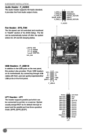
... it [4] Data it [5] Data it [6] Data it 's default interrupt request and the parallel port has three operation mode: [SPP], [EPP], [ECP]. cables with them, user can be connected to the USB ports on the rear panel, this product also provides 10-pin USB headers VCC on the front panel. HARDWARE INSTALLATION Audio Header : F_AUDIO The audio header supports HD Audio standard. The fan can quickly expand another D+ USB ports on its motherboard. By connecting through USB D-
... it [4] Data it [5] Data it [6] Data it 's default interrupt request and the parallel port has three operation mode: [SPP], [EPP], [ECP]. cables with them, user can be connected to the USB ports on the rear panel, this product also provides 10-pin USB headers VCC on the front panel. HARDWARE INSTALLATION Audio Header : F_AUDIO The audio header supports HD Audio standard. The fan can quickly expand another D+ USB ports on its motherboard. By connecting through USB D-

User manual
Page 18
... (S0 status), the LED is blinking; Power Switch Connector (PWR-SW) Connect to the Reset switch on the front panel of the hard disks. Serial ATA Connectors : SATA_1/2/3/4 The Serial ATA connector is used to be turned on . PWR-LED - HARDWARE INSTALLATION 12 + + HDD-LED - When the system is in S3/S4 sleep state or power off mode (S5), the LED is directional with +/- This 2-pin connector is off rather than using the power supply button. TPM Header : TPM The TPM...
... (S0 status), the LED is blinking; Power Switch Connector (PWR-SW) Connect to the Reset switch on the front panel of the hard disks. Serial ATA Connectors : SATA_1/2/3/4 The Serial ATA connector is used to be turned on . PWR-LED - HARDWARE INSTALLATION 12 + + HDD-LED - When the system is in S3/S4 sleep state or power off mode (S5), the LED is directional with +/- This 2-pin connector is off rather than using the power supply button. TPM Header : TPM The TPM...
User manual
Page 20
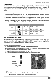
... with pins 2-3 closed Clear CMOS Jumper: CLR_CMOS The motherboard uses CMOS RAM to store the basic hardware information (such as described in next chapter. 1 Clear 2 3 Normal 1 2 (Default) 3 CLR_CMOS CAUTION ■ Disconnect the power cable before adjusting the jumper settings. ■ Do not clear the CMOS while the system is turned on the two pins to configure new system as BIOS data, date, time information, hardware password...etc.). The steps to short them...
... with pins 2-3 closed Clear CMOS Jumper: CLR_CMOS The motherboard uses CMOS RAM to store the basic hardware information (such as described in next chapter. 1 Clear 2 3 Normal 1 2 (Default) 3 CLR_CMOS CAUTION ■ Disconnect the power cable before adjusting the jumper settings. ■ Do not clear the CMOS while the system is turned on the two pins to configure new system as BIOS data, date, time information, hardware password...etc.). The steps to short them...
User manual
Page 21
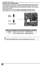
... chipset. HARDWARE INSTALLATION Intel® ME Jumper: PCH_ME_ENABLE This motherboard uses this jumper to improve management of corporate assets. CAUTION 14 It provides latest IT management features such as Intel® AMT, that allows to enable or disable Intel® Management Engine function. Enable 1 2 (Default) 3 1 Disable 2 3 PCH_ME_ENABLE Definition 1-2(default) 2-3 Description Set Pin 1 and Pin 2 closed Set Pin 2 and Pin 3 closed Function Enable ME function Disable ME function Before flashing BIOS ROM, you can disable...
... chipset. HARDWARE INSTALLATION Intel® ME Jumper: PCH_ME_ENABLE This motherboard uses this jumper to improve management of corporate assets. CAUTION 14 It provides latest IT management features such as Intel® AMT, that allows to enable or disable Intel® Management Engine function. Enable 1 2 (Default) 3 1 Disable 2 3 PCH_ME_ENABLE Definition 1-2(default) 2-3 Description Set Pin 1 and Pin 2 closed Set Pin 2 and Pin 3 closed Function Enable ME function Disable ME function Before flashing BIOS ROM, you can disable...

User manual
Page 23
... and error, to prevent unauthorized use of your current system. Power on . Security The Administrator/User password can press key to read/change you to key in the BIOS Setup, and we shall not be optimized. What you to enter Setup. Each function is explained below: Main It displays the basic system configuration, such as less I /O cards installed. BIOS SETUP Enter BIOS Setup The BIOS is the communication bridge between hardware and software, correctly setting...
... and error, to prevent unauthorized use of your current system. Power on . Security The Administrator/User password can press key to read/change you to key in the BIOS Setup, and we shall not be optimized. What you to enter Setup. Each function is explained below: Main It displays the basic system configuration, such as less I /O cards installed. BIOS SETUP Enter BIOS Setup The BIOS is the communication bridge between hardware and software, correctly setting...
User manual
Page 26
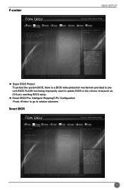
...: Optimized Defaults F4: Save & Exit ESC/Right Click: Exit Version 2.15.1236. Copyright (C) 2013 American Megatrends, Inc. 19 F-center BIOS SETUP Main F-center Advanced Boot Power Health Super BIOS Protect ▶ Smart BIOS ▶ Fox Intelligent Stepping ▶ CPU Configuration [Disabled] Security Save&Exit Super BIOS Protection Settings → ←: Select Screen ↑ ↓/Click: Select Item Enter/Dbl Click: Select +/-: Change Opt. Smart BIOS Main F-center Advanced Boot Smart BIOS Power Health Smart Power LED Smart Boot Menu [Disabled] [Enabled...
...: Optimized Defaults F4: Save & Exit ESC/Right Click: Exit Version 2.15.1236. Copyright (C) 2013 American Megatrends, Inc. 19 F-center BIOS SETUP Main F-center Advanced Boot Power Health Super BIOS Protect ▶ Smart BIOS ▶ Fox Intelligent Stepping ▶ CPU Configuration [Disabled] Security Save&Exit Super BIOS Protection Settings → ←: Select Screen ↑ ↓/Click: Select Item Enter/Dbl Click: Select +/-: Change Opt. Smart BIOS Main F-center Advanced Boot Smart BIOS Power Health Smart Power LED Smart Boot Menu [Disabled] [Enabled...

User manual
Page 27
... Reboot & Memory OK Reboot & Display OK Enter Setup or Skip ► Smart Boot Menu When PC starts, it will ask you had better disable it. 20 This also prevents user without password trying to get into your motherboard to indicate different states during Power On Self Test (POST). F1: General Help F2: Previous Values F3: Optimized Defaults F4: Save & Exit ESC/Right Click: Exit Version 2.15...
... Reboot & Memory OK Reboot & Display OK Enter Setup or Skip ► Smart Boot Menu When PC starts, it will ask you had better disable it. 20 This also prevents user without password trying to get into your motherboard to indicate different states during Power On Self Test (POST). F1: General Help F2: Previous Values F3: Optimized Defaults F4: Save & Exit ESC/Right Click: Exit Version 2.15...
User manual
Page 28
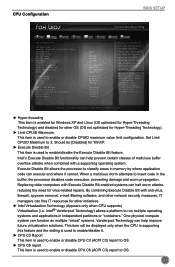
.... ► Execute Disable Bit This item is used to enable or disable CPUID maximum value limit configuration. CPU Configuration BIOS SETUP Main F-center Advanced Boot CPU Configuration CPU Brand Name: Intel(R) Celeron(R) CPU 847 @ 1.10GHz CPU Signature Microcode Patch Max CPU Speed Min CPU Speed CPU Speed Processor Cores Intel HT Technology Intel VT-x Technology Intel SMX Technology 64-bit L1 Data Cache L1 Code Cache L2 Cache L3 Cache Hyper-threading Limit CPUID Maximum Execute Disable Bit Intel Virtualization Technology CPU C3 Report CPU C6 report...
.... ► Execute Disable Bit This item is used to enable or disable CPUID maximum value limit configuration. CPU Configuration BIOS SETUP Main F-center Advanced Boot CPU Configuration CPU Brand Name: Intel(R) Celeron(R) CPU 847 @ 1.10GHz CPU Signature Microcode Patch Max CPU Speed Min CPU Speed CPU Speed Processor Cores Intel HT Technology Intel VT-x Technology Intel SMX Technology 64-bit L1 Data Cache L1 Code Cache L2 Cache L3 Cache Hyper-threading Limit CPUID Maximum Execute Disable Bit Intel Virtualization Technology CPU C3 Report CPU C6 report...
User manual
Page 30
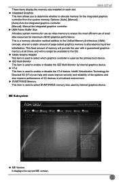
... internal graphics device. ► VT-d This item is allocated during driver initialization. Manual the integrated graphics controller. ► UMA Frame Buffer Size Allocates system memory for use of I/O devices in virtualized environment. ► DVMT/FIXED Memory This item is used to allocate memory for maximum 2D/3D graphics performance. ME Subsystem Main F-center Advanced Boot Intel ME Subsystem Configuration ME Version Power Health 8.1.30.1350 Security Save&Exit → ←: Select Screen...
... internal graphics device. ► VT-d This item is allocated during driver initialization. Manual the integrated graphics controller. ► UMA Frame Buffer Size Allocates system memory for use of I/O devices in virtualized environment. ► DVMT/FIXED Memory This item is used to allocate memory for maximum 2D/3D graphics performance. ME Subsystem Main F-center Advanced Boot Intel ME Subsystem Configuration ME Version Power Health 8.1.30.1350 Security Save&Exit → ←: Select Screen...
User manual
Page 31
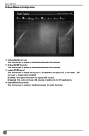
BIOS SETUP Onboard Device Configuration Main F-center Advanced Boot Power Health Security Save&Exit Onboard Device Configuration Onboard LAN Controller Onboard USB Controller Legacy USB Support Azalia HD Audio controller [Enabled] [Enabled] [Enabled] [Enabled] Enabled/Disabled Onboard LAN Controller. → ←: Select Screen ↑ ↓/Click: Select Item Enter/Dbl Click: Select +/-: Change Opt. If you have a USB keyboard or mouse, set to enabled. [Enabled]: This option will enable the legacy USB support. [Disabled]: This option will keep USB devices available only ...
BIOS SETUP Onboard Device Configuration Main F-center Advanced Boot Power Health Security Save&Exit Onboard Device Configuration Onboard LAN Controller Onboard USB Controller Legacy USB Support Azalia HD Audio controller [Enabled] [Enabled] [Enabled] [Enabled] Enabled/Disabled Onboard LAN Controller. → ←: Select Screen ↑ ↓/Click: Select Item Enter/Dbl Click: Select +/-: Change Opt. If you have a USB keyboard or mouse, set to enabled. [Enabled]: This option will enable the legacy USB support. [Disabled]: This option will keep USB devices available only ...
User manual
Page 32
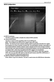
... SATA drives may not support AHCI, unless they are labeled with AHCI support in its submenu. F1: General Help F2: Previous Values F3: Optimized Defaults F4: Save & Exit ESC/Right Click: Exit Version 2.15.1236. SATA Configuration BIOS SETUP Main F-center Advanced Boot Power Health Security Save&Exit SATA Configuration SATA Controller(s) Onboard SATA Mode ▶ SATA Port1: Not Present ▶ SATA Port2: Not Present ▶ SATA Port3: Not Present ▶ SATA Port4: Not Present [Enabled] [IDE] Enable or disable SATA Device...
... SATA drives may not support AHCI, unless they are labeled with AHCI support in its submenu. F1: General Help F2: Previous Values F3: Optimized Defaults F4: Save & Exit ESC/Right Click: Exit Version 2.15.1236. SATA Configuration BIOS SETUP Main F-center Advanced Boot Power Health Security Save&Exit SATA Configuration SATA Controller(s) Onboard SATA Mode ▶ SATA Port1: Not Present ▶ SATA Port2: Not Present ▶ SATA Port3: Not Present ▶ SATA Port4: Not Present [Enabled] [IDE] Enable or disable SATA Device...
User manual
Page 35
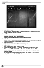
... devices required to launch active boot option. BIOS SETUP Boot Main F-center Advanced Boot Boot Configuration Bootup Numlock State Quiet Boot Fast Boot INT19 Trap Response ▶ CSM parameters Set Boot Priority 1st Boot 2nd Boot 3rd Boot 4th Boot 5th Boot 6th Boot 7th Boot 8th Boot ▶ USB HardDisk Drive BBS Priorities ▶ USB KEY Drive BBS Priorities ▶ UEFI Boot Drive BBS Prioriies Power Health [On] [Enabled] [Disabled] [Enabled] [Hard Disk] [CD/DVD] [USB Floppy] [USB CD/DVD] [USB Hard Disk] [USB KEY] [Network] [UEFI...
... devices required to launch active boot option. BIOS SETUP Boot Main F-center Advanced Boot Boot Configuration Bootup Numlock State Quiet Boot Fast Boot INT19 Trap Response ▶ CSM parameters Set Boot Priority 1st Boot 2nd Boot 3rd Boot 4th Boot 5th Boot 6th Boot 7th Boot 8th Boot ▶ USB HardDisk Drive BBS Priorities ▶ USB KEY Drive BBS Priorities ▶ UEFI Boot Drive BBS Prioriies Power Health [On] [Enabled] [Disabled] [Enabled] [Hard Disk] [CD/DVD] [USB Floppy] [USB CD/DVD] [USB Hard Disk] [USB KEY] [Network] [UEFI...

User manual
Page 38
... suspend power of motherboard. BIOS SETUP return to previous state when the STR function wakes. ► Resume By PS2 KB/Mouse This item is used to enable or disable the PS2 keyboard/Mouse to generate a wake up. ► Resume By USB Device(s) This item is used to enable or disable the USB device(s) to generate a wake up. ► Resume By PCIE Device(s) This item is used to enable or disable the PCI Express device to generate a wake...
... suspend power of motherboard. BIOS SETUP return to previous state when the STR function wakes. ► Resume By PS2 KB/Mouse This item is used to enable or disable the PS2 keyboard/Mouse to generate a wake up. ► Resume By USB Device(s) This item is used to enable or disable the USB device(s) to generate a wake up. ► Resume By PCIE Device(s) This item is used to enable or disable the PCI Express device to generate a wake...

User manual
Page 39
... (C) 2013 American Megatrends, Inc. ► Case Open Warning This item is used to enable or disable case open warning function. ► CPU Warning Temperature This option is used to set the warning temperature for the system. Default value 32 BIOS SETUP Health Main F-center Advanced Boot Case Open Warning CPU Temperature System Temperature CPU Fan Speed System Fan Speed CPUVcore VDDR +12V SYS +5V SYS 5V DUAL VBAT CPU Warning Temperature CPU Shutdowm Temperature CPU Smart Fan Control System Smart Fan Control Power Health [Disabled] : +84 ˚C : +35 ˚...
... (C) 2013 American Megatrends, Inc. ► Case Open Warning This item is used to enable or disable case open warning function. ► CPU Warning Temperature This option is used to set the warning temperature for the system. Default value 32 BIOS SETUP Health Main F-center Advanced Boot Case Open Warning CPU Temperature System Temperature CPU Fan Speed System Fan Speed CPUVcore VDDR +12V SYS +5V SYS 5V DUAL VBAT CPU Warning Temperature CPU Shutdowm Temperature CPU Smart Fan Control System Smart Fan Control Power Health [Disabled] : +84 ˚C : +35 ˚...
User manual
Page 41
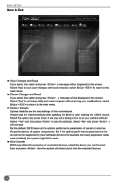
... to the main menu. ► Discard Changes and Reset If you select this option and press Enter, it will pop out a dialogue box to let you want to work. ► Boot Override BIOS auto detect the presence of system components. By this motherboard. BIOS SETUP Save & Exit Main F-center Advanced Boot Save Changes and Reset Discard Changes and Reset Restore Defaults Boot Override Foxconn MS USB2.0 Reade9144 UEFI: Foxconn MS USB2.0 Reade9144 Foxconn CF USB2...
... to the main menu. ► Discard Changes and Reset If you select this option and press Enter, it will pop out a dialogue box to let you want to work. ► Boot Override BIOS auto detect the presence of system components. By this motherboard. BIOS SETUP Save & Exit Main F-center Advanced Boot Save Changes and Reset Discard Changes and Reset Restore Defaults Boot Override Foxconn MS USB2.0 Reade9144 UEFI: Foxconn MS USB2.0 Reade9144 Foxconn CF USB2...

User manual
Page 43
Install Driver Use these options to install it first. You must click "Intel Chipset Driver" to Install 36 Manual Installation Step by Step Automatic Installation by One Click Drop to System Tray Exit the program Visit Foxconn's Show Utilities Show Drivers Browse CD View User's Manual website Choose the items you want to install, or you want to install it manually. CD INSTRUCTION 4-1 Install driver and utility 1. After that, you can click "One Click Setup" and then choose the items you can click on each individual driver to install all the drivers for your system.
Install Driver Use these options to install it first. You must click "Intel Chipset Driver" to Install 36 Manual Installation Step by Step Automatic Installation by One Click Drop to System Tray Exit the program Visit Foxconn's Show Utilities Show Drivers Browse CD View User's Manual website Choose the items you want to install, or you want to install it manually. CD INSTRUCTION 4-1 Install driver and utility 1. After that, you can click "One Click Setup" and then choose the items you can click on each individual driver to install all the drivers for your system.


