User manual
Page 1
D70S Series Motherboard User's Manual
D70S Series Motherboard User's Manual

User manual
Page 2
...want more detailed information about our products, please visit: http://www.foxconnchannel.com © All rights reserved. All images are for D70S Series motherboard. Trademark: All trademarks are registered trademarks of respective manufacturers listed. WEEE: The use motherboard better, and tells you how...contact your local city office, your household waste disposal service or the shop where you purchased this product is the intellectual property of Foxconn, Inc. By ensuring this product. CAUTION Statement: This manual is disposed of correctly, you will help you to avoid problems....
...want more detailed information about our products, please visit: http://www.foxconnchannel.com © All rights reserved. All images are for D70S Series motherboard. Trademark: All trademarks are registered trademarks of respective manufacturers listed. WEEE: The use motherboard better, and tells you how...contact your local city office, your household waste disposal service or the shop where you purchased this product is the intellectual property of Foxconn, Inc. By ensuring this product. CAUTION Statement: This manual is disposed of correctly, you will help you to avoid problems....
User manual
Page 3
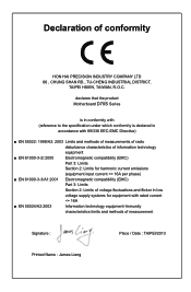
... technology equipment ■ EN 61000-3-2/:2000 Electromagnetic compatibility (EMC) Part 3: Limits Section 2: Limits for harmonic current emissions (equipment input current declares that the product Motherboard D70S Series is in conformity with (reference to the specification under which conformity is declared in accordance with 89/336 EEC-EMC Directive) ■ EN 55022...
... technology equipment ■ EN 61000-3-2/:2000 Electromagnetic compatibility (EMC) Part 3: Limits Section 2: Limits for harmonic current emissions (equipment input current declares that the product Motherboard D70S Series is in conformity with (reference to the specification under which conformity is declared in accordance with 89/336 EEC-EMC Directive) ■ EN 55022...
User manual
Page 4
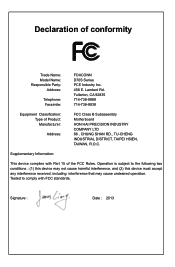
... FCC standards. Fullerton, CA 92835 714-738-8868 714-738-8838 Equipment Classification: Type of conformity Trade Name: Model Name: Responsible Party: Address: Telephone: Facsimile: FOXCONN D70S Series PCE Industry Inc. 458 E. Declaration of Product: Manufacturer: Address: FCC Class B Subassembly Motherboard HON HAI PRECISION INDUSTRY COMPANY LTD 66 , CHUNG SHAN RD., TU...
... FCC standards. Fullerton, CA 92835 714-738-8868 714-738-8838 Equipment Classification: Type of conformity Trade Name: Model Name: Responsible Party: Address: Telephone: Facsimile: FOXCONN D70S Series PCE Industry Inc. 458 E. Declaration of Product: Manufacturer: Address: FCC Class B Subassembly Motherboard HON HAI PRECISION INDUSTRY COMPANY LTD 66 , CHUNG SHAN RD., TU...
User manual
Page 5
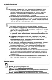
Please wear an electrostatic discharge (ESD) wrist strap when handling components such as a spark which will quickly damage your system, we recommend using a 24-pin ATX power supply to get the best performance. ■ Before turning on the motherboard. Incorrect connections might damage the motherboard. ■ When handling the motherboard, avoid touching any metal leads or connectors. ■ If there is a PCI Express x16 graphics card installed in order to avoid damage to the motherboard and CPU due to high temperature. CAUTION Installation Precautions ■ Electrostatic ...
Please wear an electrostatic discharge (ESD) wrist strap when handling components such as a spark which will quickly damage your system, we recommend using a 24-pin ATX power supply to get the best performance. ■ Before turning on the motherboard. Incorrect connections might damage the motherboard. ■ When handling the motherboard, avoid touching any metal leads or connectors. ■ If there is a PCI Express x16 graphics card installed in order to avoid damage to the motherboard and CPU due to high temperature. CAUTION Installation Precautions ■ Electrostatic ...

User manual
Page 6
Install Driver 36 2. Voltage Control (Optional 48 6. CPU Page - CPU Control 42 3. Frequency Control (Optional 45 4. Limit Setting 45 5. Fan Control 48 Frequency Page - Main Page 39 2. Voltage Page - Install Utility 37 4-2 FOX ONE 38 1. Fan Page - Table of Contents Chapter 1 Product Introduction 1-1 Product Specifications 2 1-2 Layout...4 1-3 Back Panel Connectors 5 Chapter 2 Hardware Installation 2-1 Install the Memory 8 2-2 Install other Internal Connectors 9 2-3 Jumpers 13 Chapter 3 BIOS Setup Enter BIOS Setup 16 Main...17 F-center...19 Smart BIOS 19 Fox...
Install Driver 36 2. Voltage Control (Optional 48 6. CPU Page - CPU Control 42 3. Frequency Control (Optional 45 4. Limit Setting 45 5. Fan Control 48 Frequency Page - Main Page 39 2. Voltage Page - Install Utility 37 4-2 FOX ONE 38 1. Fan Page - Table of Contents Chapter 1 Product Introduction 1-1 Product Specifications 2 1-2 Layout...4 1-3 Back Panel Connectors 5 Chapter 2 Hardware Installation 2-1 Install the Memory 8 2-2 Install other Internal Connectors 9 2-3 Jumpers 13 Chapter 3 BIOS Setup Enter BIOS Setup 16 Main...17 F-center...19 Smart BIOS 19 Fox...

User manual
Page 7
Local Update 49 2. Online Update 51 3. Configure 54 4. About & Help 56 4-4 FOX LOGO 57 4-5 FOX DMI 58 4-6 Smart charger 58 4-3 FOX LiveUpdate 49 1.
Local Update 49 2. Online Update 51 3. Configure 54 4. About & Help 56 4-4 FOX LOGO 57 4-5 FOX DMI 58 4-6 Smart charger 58 4-3 FOX LiveUpdate 49 1.

User manual
Page 8
Chapter 1 Product Introduction Thank you need for buying Foxconn D70S Series motherboard. Foxconn products are engineered to maximize computing power, providing only what you for break-through performance. This chapter includes the following information: ■ Product Specifications ■ Layout ■ Back Panel Connectors
Chapter 1 Product Introduction Thank you need for buying Foxconn D70S Series motherboard. Foxconn products are engineered to maximize computing power, providing only what you for break-through performance. This chapter includes the following information: ■ Product Specifications ■ Layout ■ Back Panel Connectors

User manual
Page 9
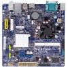
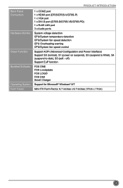
PRODUCT INTRODUCTION 1-1 Product Specifications CPU Support Intel® Celeron 847(D70S-V/-VD)&1007u(D70S/-D)&1037u (D70S-P/-PD) Dual-core Processors Max processor power up to 17W For the latest CPU information, please visit: http://www.foxconnsupport.com/cpusupportlist.aspx Chipset Intel&#...
PRODUCT INTRODUCTION 1-1 Product Specifications CPU Support Intel® Celeron 847(D70S-V/-VD)&1007u(D70S/-D)&1037u (D70S-P/-PD) Dual-core Processors Max processor power up to 17W For the latest CPU information, please visit: http://www.foxconnsupport.com/cpusupportlist.aspx Chipset Intel&#...
User manual
Page 10
... x 6.7 inches (17cm x 17cm) 3 PRODUCT INTRODUCTION Back Panel Connectors Hardware Monitor Green Function Bundled Software Operating System Form Factor 1 x COM2 port 1 x HDMI port (D70S/D70S-V/D70S-P) 1 x VGA port 1 x DVI-D port (D70S-D/D70S-VD/D70S-PD) 1 x RJ45 LAN port 3 x Audio ports System voltage detection CPU/System temperature detection CPU/System fan speed detection CPU Overheating warning CPU/System...
... x 6.7 inches (17cm x 17cm) 3 PRODUCT INTRODUCTION Back Panel Connectors Hardware Monitor Green Function Bundled Software Operating System Form Factor 1 x COM2 port 1 x HDMI port (D70S/D70S-V/D70S-P) 1 x VGA port 1 x DVI-D port (D70S-D/D70S-VD/D70S-PD) 1 x RJ45 LAN port 3 x Audio ports System voltage detection CPU/System temperature detection CPU/System fan speed detection CPU Overheating warning CPU/System...
User manual
Page 11
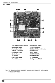
System_Fan Header 3. ME Header 8. Front Panel Header 11. LPT Header 15. Chipset: Intel® NM70 Note : The above motherboard layout is for reference only, please refer to the physical motherboard for detail. 4 PCI Express X1 Slot 6. Clear CMOS Header 9. COM1 Header 17. PRODUCT INTRODUCTION 1-2 Layout 43 2 1 5 18 6 7 8 17 9 16 10 11 12 13 14 15 1. 4-pin ATX 12V Power Connector 2. Front USB Headers 10. Front Audio Header 4. SATA Connectors 12. 24-pin ATX Power Connector 13. DDR3 DIMM Slot 16. MINI PCI Express Slot 5. TPM Header 18. Speaker Header 7....
System_Fan Header 3. ME Header 8. Front Panel Header 11. LPT Header 15. Chipset: Intel® NM70 Note : The above motherboard layout is for reference only, please refer to the physical motherboard for detail. 4 PCI Express X1 Slot 6. Clear CMOS Header 9. COM1 Header 17. PRODUCT INTRODUCTION 1-2 Layout 43 2 1 5 18 6 7 8 17 9 16 10 11 12 13 14 15 1. 4-pin ATX 12V Power Connector 2. Front USB Headers 10. Front Audio Header 4. SATA Connectors 12. 24-pin ATX Power Connector 13. DDR3 DIMM Slot 16. MINI PCI Express Slot 5. TPM Header 18. Speaker Header 7....

User manual
Page 12
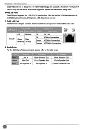
... supports DVI-D specification. Connect a monitor that supports DVI-D connec tion to transmit the uncompressed audio/video signals and is output of 5.1 channel (D70S/D70S-V/D70S-P): PS/2 Mouse Port 1 COM2 Port 3 LAN Port 7 Line In Line Out Microphone In 2 PS/2 Keyboard Port 4 VGA Port 5 HDMI... Port 6 USB Ports 8 Audio Ports 1. HDMI Port (D70S/D70S-V/D70S-P) The HDMI (High-Definition Multimedia Interface) provides an all-digital audio/video interface to this port. 5. VGA Port To connect with external ...
... supports DVI-D specification. Connect a monitor that supports DVI-D connec tion to transmit the uncompressed audio/video signals and is output of 5.1 channel (D70S/D70S-V/D70S-P): PS/2 Mouse Port 1 COM2 Port 3 LAN Port 7 Line In Line Out Microphone In 2 PS/2 Keyboard Port 4 VGA Port 5 HDMI... Port 6 USB Ports 8 Audio Ports 1. HDMI Port (D70S/D70S-V/D70S-P) The HDMI (High-Definition Multimedia Interface) provides an all-digital audio/video interface to this port. 5. VGA Port To connect with external ...
User manual
Page 13
PRODUCT INTRODUCTION audio/video device to 10/100/1000Mb/s data rate. RJ45 LAN Port The Ethernet LAN port provides Internet connection at up to this port for USB devices such as an USB keyboard/mouse, USB printer, USB flash drive and etc. 7. LAN Type 1000M Left: Active Status Description Status Off No Link Off Green Data Blinking Activity Off Green Orange Right: Link Description No Link 10Mb/s Connection 100Mb/s Connection 1000Mb/s Connection 8. Audio Ports For the definition of 1920x1080p but the actual resolutions supported depend on the monitor being used. 6.USB 2.0 Ports ...
PRODUCT INTRODUCTION audio/video device to 10/100/1000Mb/s data rate. RJ45 LAN Port The Ethernet LAN port provides Internet connection at up to this port for USB devices such as an USB keyboard/mouse, USB printer, USB flash drive and etc. 7. LAN Type 1000M Left: Active Status Description Status Off No Link Off Green Data Blinking Activity Off Green Orange Right: Link Description No Link 10Mb/s Connection 100Mb/s Connection 1000Mb/s Connection 8. Audio Ports For the definition of 1920x1080p but the actual resolutions supported depend on the monitor being used. 6.USB 2.0 Ports ...

User manual
Page 14
Please refer to the motherboard layout prior to any installation and read the contents in this chapter carefully. This chapter includes the following information : ■ Install the Memory ■ Install other Internal Connectors ■ Jumpers Chapter 2 Hardware Installation This chapter introduces the hardware installation process, including memory, slots, pin headers and the mounting of these modules. Caution should be exercised during the installation of jumpers.
Please refer to the motherboard layout prior to any installation and read the contents in this chapter carefully. This chapter includes the following information : ■ Install the Memory ■ Install other Internal Connectors ■ Jumpers Chapter 2 Hardware Installation This chapter introduces the hardware installation process, including memory, slots, pin headers and the mounting of these modules. Caution should be exercised during the installation of jumpers.
User manual
Page 15
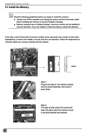
Follow the steps below to correctly install your memory modules into place when the memory moule is securely inserted and pressed. 8 If you begin to install the memory : ■ Always turn off the computer and unplug the power cord from the power outlet before installing the memory to prevent hardware damage. ■ Memory modules have a foolproof design. Step 2: The clips at front side of memory module, it has asymmetric pin counts on both ends of the memory module into the socket slantwise, then press it can be installed in one direction. If you take a look at both sides ...
Follow the steps below to correctly install your memory modules into place when the memory moule is securely inserted and pressed. 8 If you begin to install the memory : ■ Always turn off the computer and unplug the power cord from the power outlet before installing the memory to prevent hardware damage. ■ Memory modules have a foolproof design. Step 2: The clips at front side of memory module, it has asymmetric pin counts on both ends of the memory module into the socket slantwise, then press it can be installed in one direction. If you take a look at both sides ...
User manual
Page 16
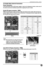
Make sure that the power supply cable and pins are using a 24-pin power supply. Pin # Definition Pin # Definition 1 3.3V 13 3.3V 2 3.3V 14 -12V 3 GND 15 GND 4 +5V 16 PS_ON(Soft On/Off) 5 GND 17 GND 6 +5V 18 GND 7 GND 19 GND 8 Power Good 20 NC 9 +5V SB(Stand by +5V) 21 +5V 10 +12V 22 +5V 24 13 11 +12V 23 +5V 12 3.3V 24 GND 12 PWR1 1 Pin No. 24 We recommend you are properly aligned with the connector on the motherboard. If you using a 20-pin power supply, you need to align the ATX power connector according to the picture. 20-Pin ...
Make sure that the power supply cable and pins are using a 24-pin power supply. Pin # Definition Pin # Definition 1 3.3V 13 3.3V 2 3.3V 14 -12V 3 GND 15 GND 4 +5V 16 PS_ON(Soft On/Off) 5 GND 17 GND 6 +5V 18 GND 7 GND 19 GND 8 Power Good 20 NC 9 +5V SB(Stand by +5V) 21 +5V 10 +12V 22 +5V 24 13 11 +12V 23 +5V 12 3.3V 24 GND 12 PWR1 1 Pin No. 24 We recommend you are properly aligned with the connector on the motherboard. If you using a 20-pin power supply, you need to align the ATX power connector according to the picture. 20-Pin ...
User manual
Page 17
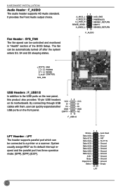
cables with them, user can be controlled and monitored in "Health" section of the BIOS Setup. System usually assign IRQ7 as it [7] ACK Busy Paper End Select 12 25 26 LPT Auto Feed Error INIT SLCT IN Ground Ground Ground Ground Ground Ground Ground Ground Empty 10 It provides the Front Audio output choice. GND EMPTY 12 9 10 VCC DD+ GND NC F_USB1/2 LPT Hearder : LPT The header supports parallel port which can quickly expand another D+ USB ports on its motherboard. HARDWARE INSTALLATION Audio Header : F_AUDIO The audio header supports HD Audio standard. Fan Header : ...
cables with them, user can be controlled and monitored in "Health" section of the BIOS Setup. System usually assign IRQ7 as it [7] ACK Busy Paper End Select 12 25 26 LPT Auto Feed Error INIT SLCT IN Ground Ground Ground Ground Ground Ground Ground Ground Empty 10 It provides the Front Audio output choice. GND EMPTY 12 9 10 VCC DD+ GND NC F_USB1/2 LPT Hearder : LPT The header supports parallel port which can quickly expand another D+ USB ports on its motherboard. HARDWARE INSTALLATION Audio Header : F_AUDIO The audio header supports HD Audio standard. Fan Header : ...

User manual
Page 18
It indicates the active status of the chassis. the system will restart when the switch is blinking; The Power LED indicates the system's status. When the system is in S3/S4 sleep state or power off mode (S5), the LED is off rather than using the power supply button. When the system is in operation (S0 status), the LED is used to the Reset switch on the front panel of the hard disks. Power Switch Connector (PWR-SW) Connect to the power LED indicator on the front panel of the chassis. sign. Power LED Connector (PWR-LED) Connect to the power button on . When the system ...
It indicates the active status of the chassis. the system will restart when the switch is blinking; The Power LED indicates the system's status. When the system is in S3/S4 sleep state or power off mode (S5), the LED is off rather than using the power supply button. When the system is in operation (S0 status), the LED is used to the Reset switch on the front panel of the hard disks. Power Switch Connector (PWR-SW) Connect to the power LED indicator on the front panel of the chassis. sign. Power LED Connector (PWR-LED) Connect to the power button on . When the system ...
User manual
Page 19
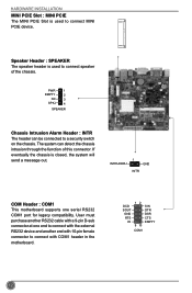
Speaker Header : SPEAKER The speaker header is closed, the system will send a message out. INTRUDERJ 1 GND INTR COM Header : COM1 This motherboard supports one end to connect with the external RS232 device and another RS232 cable with a 9-pin D-sub connector at one serial RS232 COM1 port for legacy compatibility. DCD SOUT GND RTS RI 12 9 10 SIN DTR DSR CTS EMPTY COM1 12 PWR 1 EMPTY 2 NC 3 SPKJ 4 SPEAKER Chassis Intrusion Alarm Header : INTR The header can detect the chassis intrusion through the function of the chassis. User must purchase another end with ...
Speaker Header : SPEAKER The speaker header is closed, the system will send a message out. INTRUDERJ 1 GND INTR COM Header : COM1 This motherboard supports one end to connect with the external RS232 device and another RS232 cable with a 9-pin D-sub connector at one serial RS232 COM1 port for legacy compatibility. DCD SOUT GND RTS RI 12 9 10 SIN DTR DSR CTS EMPTY COM1 12 PWR 1 EMPTY 2 NC 3 SPKJ 4 SPEAKER Chassis Intrusion Alarm Header : INTR The header can detect the chassis intrusion through the function of the chassis. User must purchase another end with ...
User manual
Page 20
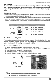
However, in this motherboard, Pin 1 can prevent hazardous ESD (Electrical Static Discharge) problem. The shorting can also be identified by the bold silkscreen next to it. Jumper 1 1 Diagram 1 1 1 1 Definition Closed Open 1-2 2-3 Description Set Pin 1 and Pin 2 closed Set Pin 1 and Pin 2 Open Set Pin 1 and Pin 2 closed Set Pin 2 and Pin 3 closed . 4. Plug in next chapter. 1 Clear 2 3 Normal 1 2 (Default) 3 CLR_CMOS CAUTION ■ Disconnect the power cable before adjusting the jumper settings. ■ Do not clear the CMOS while the system is simply labeled as "1". 2....
However, in this motherboard, Pin 1 can prevent hazardous ESD (Electrical Static Discharge) problem. The shorting can also be identified by the bold silkscreen next to it. Jumper 1 1 Diagram 1 1 1 1 Definition Closed Open 1-2 2-3 Description Set Pin 1 and Pin 2 closed Set Pin 1 and Pin 2 Open Set Pin 1 and Pin 2 closed Set Pin 2 and Pin 3 closed . 4. Plug in next chapter. 1 Clear 2 3 Normal 1 2 (Default) 3 CLR_CMOS CAUTION ■ Disconnect the power cable before adjusting the jumper settings. ■ Do not clear the CMOS while the system is simply labeled as "1". 2....