
User manual
Page 9
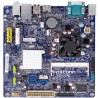
PRODUCT INTRODUCTION 1-1 Product Specifications CPU Support Intel® Celeron 847(D70S-V/-VD)&1007u(D70S/-D)&1037u (D70S-P/-PD) Dual-core Processors Max processor power up to 17W For the latest CPU information, please visit: http://.../s data transfer rate) - 1 x SATA 3.0 connectors (6Gb/s data transfer rate) LAN Realtek RTL8111F Gigabit LAN controller Support 10/100/1000Mbps Audio Realtek ALC662 -High Definition Audio -2/4/5.1-channel -Support Jack-Sensing function USB Support up to 8 x USB 2.0 ports (4 rear panel ports, 2 onboard USB headers supporting 4 extra ports) Support ...
PRODUCT INTRODUCTION 1-1 Product Specifications CPU Support Intel® Celeron 847(D70S-V/-VD)&1007u(D70S/-D)&1037u (D70S-P/-PD) Dual-core Processors Max processor power up to 17W For the latest CPU information, please visit: http://.../s data transfer rate) - 1 x SATA 3.0 connectors (6Gb/s data transfer rate) LAN Realtek RTL8111F Gigabit LAN controller Support 10/100/1000Mbps Audio Realtek ALC662 -High Definition Audio -2/4/5.1-channel -Support Jack-Sensing function USB Support up to 8 x USB 2.0 ports (4 rear panel ports, 2 onboard USB headers supporting 4 extra ports) Support ...

User manual
Page 12
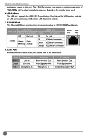
...a PS/2 keyboard. 3. PS/2 Mouse Port Use the upper port (green) to transmit the uncompressed audio/video signals and is output of 5.1 channel (D70S/D70S-V/D70S-P): PS/2 Mouse Port 1 COM2 Port 3 LAN Port 7 Line In Line Out Microphone In 2 PS/2 Keyboard Port 4 VGA Port 5 HDMI Port ...Port 4 VGA Port 5 DVI-D Port 6 USB Ports 8 Audio Ports Back panel connectors of RS232 COM2 port. 4. HDMI Port (D70S/D70S-V/D70S-P) The HDMI (High-Definition Multimedia Interface) provides an all-digital audio/video interface to connect a PS/2 mouse. 2. VGA Port To connect with external display ...
...a PS/2 keyboard. 3. PS/2 Mouse Port Use the upper port (green) to transmit the uncompressed audio/video signals and is output of 5.1 channel (D70S/D70S-V/D70S-P): PS/2 Mouse Port 1 COM2 Port 3 LAN Port 7 Line In Line Out Microphone In 2 PS/2 Keyboard Port 4 VGA Port 5 HDMI Port ...Port 4 VGA Port 5 DVI-D Port 6 USB Ports 8 Audio Ports Back panel connectors of RS232 COM2 port. 4. HDMI Port (D70S/D70S-V/D70S-P) The HDMI (High-Definition Multimedia Interface) provides an all-digital audio/video interface to connect a PS/2 mouse. 2. VGA Port To connect with external display ...
User manual
Page 13
... Microphone In 4-channel Rear Speaker Out* Front Speaker Out Microphone In 5.1-channel Rear Speaker Out* Front Speaker Out Center/Subwoofer Out* 6 Audio Ports For the definition of 1920x1080p but the actual resolutions supported depend on the monitor being used. 6.USB 2.0 Ports The USB port supports the USB 2.0/1.1 specification. Use this port...
... Microphone In 4-channel Rear Speaker Out* Front Speaker Out Microphone In 5.1-channel Rear Speaker Out* Front Speaker Out Center/Subwoofer Out* 6 Audio Ports For the definition of 1920x1080p but the actual resolutions supported depend on the monitor being used. 6.USB 2.0 Ports The USB port supports the USB 2.0/1.1 specification. Use this port...
User manual
Page 16
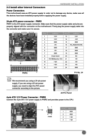
... and make sure all the devices have been installed properly before applying the power supply. 24-pin ATX power connector : PWR1 PWR1 is secure. Pin # Definition Pin # Definition 1 3.3V 13 3.3V 2 3.3V 14 -12V 3 GND 15 GND 4 +5V 16 PS_ON(Soft On/Off) 5 GND 17 GND 6 +5V 18 GND 7 GND 19 ... power to damage any device, make sure it is the ATX power supply connector. In order not to the CPU. 31 42 PWR2 Pin # 1 2 3 4 Definition GND GND +12V +12V 9 Make sure that the power supply cable and pins are using a 20-pin power supply, you using a 24-pin power supply...
... and make sure all the devices have been installed properly before applying the power supply. 24-pin ATX power connector : PWR1 PWR1 is secure. Pin # Definition Pin # Definition 1 3.3V 13 3.3V 2 3.3V 14 -12V 3 GND 15 GND 4 +5V 16 PS_ON(Soft On/Off) 5 GND 17 GND 6 +5V 18 GND 7 GND 19 ... power to damage any device, make sure it is the ATX power supply connector. In order not to the CPU. 31 42 PWR2 Pin # 1 2 3 4 Definition GND GND +12V +12V 9 Make sure that the power supply cable and pins are using a 20-pin power supply, you using a 24-pin power supply...
User manual
Page 20
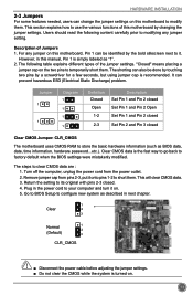
... can also be identified by the bold silkscreen next to it onto pins 1-2 to modify them. Remove jumper cap from the power outlet. 2. Jumper 1 1 Diagram 1 1 1 1 Definition Closed Open 1-2 2-3 Description Set Pin 1 and Pin 2 closed Set Pin 1 and Pin 2 Open Set Pin 1 and Pin 2 closed Set Pin 2 and Pin 3 closed . 4. Clear CMOS...
... can also be identified by the bold silkscreen next to it onto pins 1-2 to modify them. Remove jumper cap from the power outlet. 2. Jumper 1 1 Diagram 1 1 1 1 Definition Closed Open 1-2 2-3 Description Set Pin 1 and Pin 2 closed Set Pin 1 and Pin 2 Open Set Pin 1 and Pin 2 closed Set Pin 2 and Pin 3 closed . 4. Clear CMOS...
User manual
Page 21
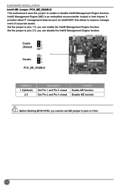
... enable or disable Intel® Management Engine function. Intel® Management Engine (ME) is an embedded microcontroller located in Intel chipset. Enable 1 2 (Default) 3 1 Disable 2 3 PCH_ME_ENABLE Definition 1-2(default) 2-3 Description Set Pin 1 and Pin 2 closed Set Pin 2 and Pin 3 closed Function Enable ME function Disable ME function Before flashing BIOS ROM, you need...
... enable or disable Intel® Management Engine function. Intel® Management Engine (ME) is an embedded microcontroller located in Intel chipset. Enable 1 2 (Default) 3 1 Disable 2 3 PCH_ME_ENABLE Definition 1-2(default) 2-3 Description Set Pin 1 and Pin 2 closed Set Pin 2 and Pin 3 closed Function Enable ME function Disable ME function Before flashing BIOS ROM, you need...