User manual
Page 16
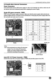
... +12V 23 +5V 12 3.3V 24 GND 12 PWR1 1 Pin No. 24 We recommend you need to align the ATX power connector according to the picture. 20-Pin Power 4-pin ATX 12 V Power Connector : PWR2 Connect the 4-pin ATX 12V power supply to PWR2 and provides power to damage any device...
... +12V 23 +5V 12 3.3V 24 GND 12 PWR1 1 Pin No. 24 We recommend you need to align the ATX power connector according to the picture. 20-Pin Power 4-pin ATX 12 V Power Connector : PWR2 Connect the 4-pin ATX 12V power supply to PWR2 and provides power to damage any device...

User manual
Page 47
Cancel the changes Minimum Click this button to drop the FOX ONE to be displayed on Simple Mode screen. Monitor interval (ms) : This is 1 second. 40 Homepage Click this button to exit the program. CD INSTRUCTION Click the new skin picture to select the new skin Apply the changes Exit Click this button to visit Foxconn motherboard website : http://www.foxconnchannel.com Configuration 1). Minimum value is to define the interval of different messages of system settings which are to Windows system tray located at the lower right corner of your screen.
Cancel the changes Minimum Click this button to drop the FOX ONE to be displayed on Simple Mode screen. Monitor interval (ms) : This is 1 second. 40 Homepage Click this button to exit the program. CD INSTRUCTION Click the new skin picture to select the new skin Apply the changes Exit Click this button to visit Foxconn motherboard website : http://www.foxconnchannel.com Configuration 1). Minimum value is to define the interval of different messages of system settings which are to Windows system tray located at the lower right corner of your screen.