User manual
Page 1
D70S Series Motherboard User's Manual
D70S Series Motherboard User's Manual
User manual
Page 2
... All rights reserved. CAUTION Statement: This manual is disposed of correctly, you will help you to the physical motherboard for specific features. All trade names are the property of their respective owners. More information: If you how to...you purchased this product may not be changed or modified at any time, Foxconn does not obligate itself to avoid problems. Caution: Indicating a potential risk of Foxconn, Inc. Version: User's Manual V1.0 for reference only, please refer ...: Refers to important information that this product. All images are for D70S Series motherboard.
... All rights reserved. CAUTION Statement: This manual is disposed of correctly, you will help you to the physical motherboard for specific features. All trade names are the property of their respective owners. More information: If you how to...you purchased this product may not be changed or modified at any time, Foxconn does not obligate itself to avoid problems. Caution: Indicating a potential risk of Foxconn, Inc. Version: User's Manual V1.0 for reference only, please refer ...: Refers to important information that this product. All images are for D70S Series motherboard.
User manual
Page 3
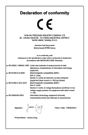
declares that the product Motherboard D70S Series is in conformity with (reference to the specification under which conformity is declared in accordance with 89/336 EEC-EMC Directive) ■ EN 55022: ...
declares that the product Motherboard D70S Series is in conformity with (reference to the specification under which conformity is declared in accordance with 89/336 EEC-EMC Directive) ■ EN 55022: ...
User manual
Page 4
... comply with Part 15 of Product: Manufacturer: Address: FCC Class B Subassembly Motherboard HON HAI PRECISION INDUSTRY COMPANY LTD 66 , CHUNG SHAN RD., TU-CHENG INDUSTRIAL DISTRICT, TAIPEI HSIEN, TAIWAN, R.O.C. Signature : Date : 2013 Declaration of conformity Trade Name: Model Name: Responsible Party: Address: Telephone: Facsimile: FOXCONN D70S Series PCE Industry Inc. 458 E. Lambert Rd.
... comply with Part 15 of Product: Manufacturer: Address: FCC Class B Subassembly Motherboard HON HAI PRECISION INDUSTRY COMPANY LTD 66 , CHUNG SHAN RD., TU-CHENG INDUSTRIAL DISTRICT, TAIPEI HSIEN, TAIWAN, R.O.C. Signature : Date : 2013 Declaration of conformity Trade Name: Model Name: Responsible Party: Address: Telephone: Facsimile: FOXCONN D70S Series PCE Industry Inc. 458 E. Lambert Rd.
User manual
Page 5
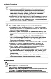
... memory, expansion cards or other peripherals. Please carefully read the following procedures to high temperature. Normal operation depends on the motherboard or within the computer casing. ■ If you are no leftover screws or metal components placed on the overclocking capacity... of the product, please consult a certified computer technician. Normally it comes out as a motherboard, CPU or memory. ■ Ensure that flows between two objects at different electrical potentials. Please wear an electrostatic discharge (ESD...
... memory, expansion cards or other peripherals. Please carefully read the following procedures to high temperature. Normal operation depends on the motherboard or within the computer casing. ■ If you are no leftover screws or metal components placed on the overclocking capacity... of the product, please consult a certified computer technician. Normally it comes out as a motherboard, CPU or memory. ■ Ensure that flows between two objects at different electrical potentials. Please wear an electrostatic discharge (ESD...
User manual
Page 8
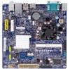
Foxconn products are engineered to maximize computing power, providing only what you for break-through performance. Chapter 1 Product Introduction Thank you need for buying Foxconn D70S Series motherboard. This chapter includes the following information: ■ Product Specifications ■ Layout ■ Back Panel Connectors
Foxconn products are engineered to maximize computing power, providing only what you for break-through performance. Chapter 1 Product Introduction Thank you need for buying Foxconn D70S Series motherboard. This chapter includes the following information: ■ Product Specifications ■ Layout ■ Back Panel Connectors
User manual
Page 11
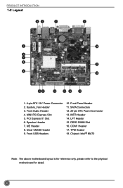
System_Fan Header 3. PCI Express X1 Slot 6. Clear CMOS Header 9. Chipset: Intel® NM70 Note : The above motherboard layout is for reference only, please refer to the physical motherboard for detail. 4 SATA Connectors 12. 24-pin ATX Power Connector 13. DDR3 DIMM Slot 16. ME Header 8. INTR Header 14. MINI PCI Express Slot 5. Speaker...
System_Fan Header 3. PCI Express X1 Slot 6. Clear CMOS Header 9. Chipset: Intel® NM70 Note : The above motherboard layout is for reference only, please refer to the physical motherboard for detail. 4 SATA Connectors 12. 24-pin ATX Power Connector 13. DDR3 DIMM Slot 16. ME Header 8. INTR Header 14. MINI PCI Express Slot 5. Speaker...

User manual
Page 14
Please refer to the motherboard layout prior to any installation and read the contents in this chapter carefully. Caution should be exercised during the installation of jumpers. This chapter includes the following information : ■ Install the Memory ■ Install other Internal Connectors ■ Jumpers Chapter 2 Hardware Installation This chapter introduces the hardware installation process, including memory, slots, pin headers and the mounting of these modules.
Please refer to the motherboard layout prior to any installation and read the contents in this chapter carefully. Caution should be exercised during the installation of jumpers. This chapter includes the following information : ■ Install the Memory ■ Install other Internal Connectors ■ Jumpers Chapter 2 Hardware Installation This chapter introduces the hardware installation process, including memory, slots, pin headers and the mounting of these modules.
User manual
Page 16
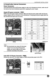
... 3.3V 24 GND 12 PWR1 1 Pin No. 24 We recommend you using a 20-pin power supply, you are properly aligned with the connector on the motherboard. If you need to align the ATX power connector according to the picture. 20-Pin Power 4-pin ATX 12 V Power Connector : PWR2 Connect the 4-pin... secure. In order not to the CPU. 31 42 PWR2 Pin # 1 2 3 4 Definition GND GND +12V +12V 9 HARDWARE INSTALLATION 2-2 Install other Internal Connectors Power Connectors This motherboard uses an ATX power supply.
... 3.3V 24 GND 12 PWR1 1 Pin No. 24 We recommend you using a 20-pin power supply, you are properly aligned with the connector on the motherboard. If you need to align the ATX power connector according to the picture. 20-Pin Power 4-pin ATX 12 V Power Connector : PWR2 Connect the 4-pin... secure. In order not to the CPU. 31 42 PWR2 Pin # 1 2 3 4 Definition GND GND +12V +12V 9 HARDWARE INSTALLATION 2-2 Install other Internal Connectors Power Connectors This motherboard uses an ATX power supply.
User manual
Page 17
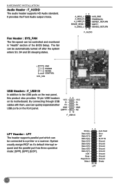
... rear panel, this product also provides 10-pin USB headers VCC on the front panel. The fan can quickly expand another D+ USB ports on its motherboard. System usually assign IRQ7 as it [7] ACK Busy Paper End Select 12 25 26 LPT Auto Feed Error INIT SLCT IN Ground Ground Ground Ground...
... rear panel, this product also provides 10-pin USB headers VCC on the front panel. The fan can quickly expand another D+ USB ports on its motherboard. System usually assign IRQ7 as it [7] ACK Busy Paper End Select 12 25 26 LPT Auto Feed Error INIT SLCT IN Ground Ground Ground Ground...

User manual
Page 18
... and off . Power LED Connector (PWR-LED) Connect to the power button on . The Power LED indicates the system's status. Front Panel Header : FP1 This motherboard includes one header for connecting the front panel switch and LED Indicators. sign. Hard Disk LED Connector (HDD-LED) Connect to make transactions and communication...
... and off . Power LED Connector (PWR-LED) Connect to the power button on . The Power LED indicates the system's status. Front Panel Header : FP1 This motherboard includes one header for connecting the front panel switch and LED Indicators. sign. Hard Disk LED Connector (HDD-LED) Connect to make transactions and communication...
User manual
Page 19
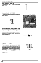
... device and another RS232 cable with a 9-pin D-sub connector at one serial RS232 COM1 port for legacy compatibility. INTRUDERJ 1 GND INTR COM Header : COM1 This motherboard supports one end to a security switch on the chassis. PWR 1 EMPTY 2 NC 3 SPKJ 4 SPEAKER Chassis Intrusion Alarm Header : INTR The header can detect the chassis... with 10-pin female connector to connect MINI PCIE device. Speaker Header : SPEAKER The speaker header is used to connect with COM1 header in the motherboard.
... device and another RS232 cable with a 9-pin D-sub connector at one serial RS232 COM1 port for legacy compatibility. INTRUDERJ 1 GND INTR COM Header : COM1 This motherboard supports one end to a security switch on the chassis. PWR 1 EMPTY 2 NC 3 SPKJ 4 SPEAKER Chassis Intrusion Alarm Header : INTR The header can detect the chassis... with 10-pin female connector to connect MINI PCIE device. Speaker Header : SPEAKER The speaker header is used to connect with COM1 header in the motherboard.
User manual
Page 20
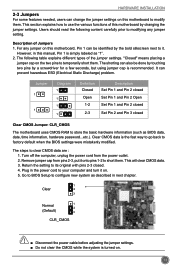
...power cord from pins 2-3, put it on. 5. Return the setting to its original with pins 2-3 closed Clear CMOS Jumper: CLR_CMOS The motherboard uses CMOS RAM to store the basic hardware information (such as "1". 2. The following content carefully prior to modifying any jumper on . ...the two pins to temporarily short them. It can prevent hazardous ESD (Electrical Static Discharge) problem. Plug in this manual, Pin 1 is turned on this motherboard to modify them. This section explains how to short them. Jumper 1 1 Diagram 1 1 1 1 Definition Closed Open 1-2 2-3 Description Set Pin 1 and...
...power cord from pins 2-3, put it on. 5. Return the setting to its original with pins 2-3 closed Clear CMOS Jumper: CLR_CMOS The motherboard uses CMOS RAM to store the basic hardware information (such as "1". 2. The following content carefully prior to modifying any jumper on . ...the two pins to temporarily short them. It can prevent hazardous ESD (Electrical Static Discharge) problem. Plug in this manual, Pin 1 is turned on this motherboard to modify them. This section explains how to short them. Jumper 1 1 Diagram 1 1 1 1 Definition Closed Open 1-2 2-3 Description Set Pin 1 and...
User manual
Page 21
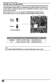
... features such as Intel® AMT, that allows to enable or disable Intel® Management Engine function. HARDWARE INSTALLATION Intel® ME Jumper: PCH_ME_ENABLE This motherboard uses this jumper to improve management of corporate assets. Set the jumper to pins 2-3 first. CAUTION 14 Intel® Management Engine (ME) is an embedded...
... features such as Intel® AMT, that allows to enable or disable Intel® Management Engine function. HARDWARE INSTALLATION Intel® ME Jumper: PCH_ME_ENABLE This motherboard uses this jumper to improve management of corporate assets. Set the jumper to pins 2-3 first. CAUTION 14 Intel® Management Engine (ME) is an embedded...

User manual
Page 27
... twice (1/3sec. If [Disabled] is a feature built on your computer through smart boot menu. This also prevents user without password trying to get into your motherboard to indicate different states during Power On Self Test (POST). Copyright (C) 2013 American Megatrends, Inc. ► Spread Spectrum If you enabled this state enabled. On...
... twice (1/3sec. If [Disabled] is a feature built on your computer through smart boot menu. This also prevents user without password trying to get into your motherboard to indicate different states during Power On Self Test (POST). Copyright (C) 2013 American Megatrends, Inc. ► Spread Spectrum If you enabled this state enabled. On...
User manual
Page 32
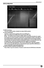
... Values F3: Optimized Defaults F4: Save & Exit ESC/Right Click: Exit Version 2.15.1236. If your SATA ports. [IDE] - The specification includes a description of your motherboard supporting AHCI, and you have a SATA device, which also supports AHCI, then you can select IDE option to have fair performance (only PATA, SATA level...
... Values F3: Optimized Defaults F4: Save & Exit ESC/Right Click: Exit Version 2.15.1236. If your SATA ports. [IDE] - The specification includes a description of your motherboard supporting AHCI, and you have a SATA device, which also supports AHCI, then you can select IDE option to have fair performance (only PATA, SATA level...

User manual
Page 38
... reduce the power consumption of the chipset will take with when it resumes after an AC power loss. 31 When enable, the suspend power of motherboard.
... reduce the power consumption of the chipset will take with when it resumes after an AC power loss. 31 When enable, the suspend power of motherboard.

User manual
Page 39
When the temperature of CPU is higher than the set value, the motherboard will shut down automatically.This function works only when your operating system is supporting ACPI. ► CPU Smart Fan Control This option is used to ...
When the temperature of CPU is higher than the set value, the motherboard will shut down automatically.This function works only when your operating system is supporting ACPI. ► CPU Smart Fan Control This option is used to ...
User manual
Page 41
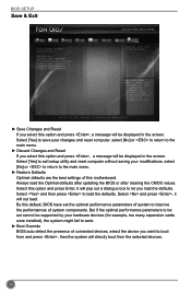
... devices. 34 But if the optimal performance parameters to the main menu. ► Discard Changes and Reset If you select this motherboard. Select and then press to boot from and press , then the system will be displayed in the screen. Copyright (C) 2013 ...center Advanced Boot Save Changes and Reset Discard Changes and Reset Restore Defaults Boot Override Foxconn MS USB2.0 Reade9144 UEFI: Foxconn MS USB2.0 Reade9144 Foxconn CF USB2.0 Reade9144 Foxconn SM USB2.0 Reade9144 Foxconn SD USB2.0 Reade9144 Power Health Security Save&Exit Reset the system after clearing the...
... devices. 34 But if the optimal performance parameters to the main menu. ► Discard Changes and Reset If you select this motherboard. Select and then press to boot from and press , then the system will be displayed in the screen. Copyright (C) 2013 ...center Advanced Boot Save Changes and Reset Discard Changes and Reset Restore Defaults Boot Override Foxconn MS USB2.0 Reade9144 UEFI: Foxconn MS USB2.0 Reade9144 Foxconn CF USB2.0 Reade9144 Foxconn SM USB2.0 Reade9144 Foxconn SD USB2.0 Reade9144 Power Health Security Save&Exit Reset the system after clearing the...

User manual
Page 42
This chapter includes the following information: ■ Install driver and utility ■ FOX ONE ■ FOX LiveUpdate ■ FOX LOGO ■ FOX DMI ■ Smart Charger Chapter 4 CD Instruction The utility CD that comes with the motherboard contains useful software and several utility drivers that enhance the motherboard features.
This chapter includes the following information: ■ Install driver and utility ■ FOX ONE ■ FOX LiveUpdate ■ FOX LOGO ■ FOX DMI ■ Smart Charger Chapter 4 CD Instruction The utility CD that comes with the motherboard contains useful software and several utility drivers that enhance the motherboard features.


