
English Manual.
Page 1
Destroyer Motherboard User's Manual
Destroyer Motherboard User's Manual

English Manual.
Page 2
...the physical motherboard for Destroyer motherboard. Although the information in this product may exist. Trademark: All trademarks are the property of hardware damage or physical injury may not be caused by inappropriate waste handling of respective manufacturers listed. Version: User's Manual V1.0 for specific ...The use motherboard better, and tells you how to important information that this manual may be changed or modified at any time, Foxconn does not obligate itself to inform the user of Foxconn, Inc. More information: If you purchased this symbol indicates that can help...
...the physical motherboard for Destroyer motherboard. Although the information in this product may exist. Trademark: All trademarks are the property of hardware damage or physical injury may not be caused by inappropriate waste handling of respective manufacturers listed. Version: User's Manual V1.0 for specific ...The use motherboard better, and tells you how to important information that this manual may be changed or modified at any time, Foxconn does not obligate itself to inform the user of Foxconn, Inc. More information: If you purchased this symbol indicates that can help...

English Manual.
Page 9
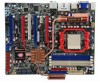
...not in the warranty, only motherboard is damaged or missing, please contact your retailer. Before your product package for the following items: Motherboard Foxconn Destroyer motherboard I/O modules Cables 1 x USB 2.0 x 2 ports and 1 x 1394a module 1 x SPDIF Out module 4 x SATA ...3-way SLI plus bridge 1 x PCB tray 1 x 50k variable resistor 1 x 20k variable resistor Copper column bolt Foxconn motherboard support CD Documentation User's manual Quick installation guide Registration card Quantum Force sticker Quantum Force tattoos Quantum Force dogtag ! 1 CAUTION Package List Check your...
...not in the warranty, only motherboard is damaged or missing, please contact your retailer. Before your product package for the following items: Motherboard Foxconn Destroyer motherboard I/O modules Cables 1 x USB 2.0 x 2 ports and 1 x 1394a module 1 x SPDIF Out module 4 x SATA ...3-way SLI plus bridge 1 x PCB tray 1 x 50k variable resistor 1 x 20k variable resistor Copper column bolt Foxconn motherboard support CD Documentation User's manual Quick installation guide Registration card Quantum Force sticker Quantum Force tattoos Quantum Force dogtag ! 1 CAUTION Package List Check your...

English Manual.
Page 20
... x16 slot. Installing and Removing a PCI Express x16 Graphics Card : • Installing a Graphics Card: Gently insert the graphics card into the slot. 4. Carefully read the manual that supports your expansion card(s). 7. Install the driver provided with the slot, and press down on the card until it is locked by the latch...
... x16 slot. Installing and Removing a PCI Express x16 Graphics Card : • Installing a Graphics Card: Gently insert the graphics card into the slot. 4. Carefully read the manual that supports your expansion card(s). 7. Install the driver provided with the slot, and press down on the card until it is locked by the latch...

English Manual.
Page 26
... touching two pins by the bold silkscreen next to use the various functions of Jumpers 1. Remove jumper cap from the power outlet. 2. Description of this manual, pin 1 is the fast way to go back to temporarily short them . Users should read the following table explains different types of the jumper settings...
... touching two pins by the bold silkscreen next to use the various functions of Jumpers 1. Remove jumper cap from the power outlet. 2. Description of this manual, pin 1 is the fast way to go back to temporarily short them . Users should read the following table explains different types of the jumper settings...

English Manual.
Page 29
...on the screen during the system Power On Self Test (POST) process. 2. Please visit our website for updated manual if it is for reference only. Detailed descriptions of this manual is available. We do not guarantee the content of the BIOS parameters are also provided. This chapter includes the... ■ Save & Exit Setup ■ Exit Without Saving Since BIOS could be updated some other times, the BIOS information described in this manual will remain consistent with the newly released BIOS at any given time in the future. You want to change the default CMOS settings.
...on the screen during the system Power On Self Test (POST) process. 2. Please visit our website for updated manual if it is for reference only. Detailed descriptions of this manual is available. We do not guarantee the content of the BIOS parameters are also provided. This chapter includes the... ■ Save & Exit Setup ■ Exit Without Saving Since BIOS could be updated some other times, the BIOS information described in this manual will remain consistent with the newly released BIOS at any given time in the future. You want to change the default CMOS settings.
English Manual.
Page 31
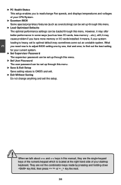
... your CPU/System. ► Quantum BIOS Some special proprietary features (such as less I/O cards, less memory ...etc.), still, it may offer better performance in this manual, they are not the combination keys made by one by pressing and holding down key first, then press or key the next. 24 3 CAUTION ►...
... your CPU/System. ► Quantum BIOS Some special proprietary features (such as less I/O cards, less memory ...etc.), still, it may offer better performance in this manual, they are not the combination keys made by one by pressing and holding down key first, then press or key the next. 24 3 CAUTION ►...

English Manual.
Page 35
...addition to memory size is small or CPU is based on , it means you can select [Auto] to let the system control, or select [Manual] to control the "Frame Buffer Size" setting. AwardBIOS CMOS Setup Utility Advanced Chipset Features x Hybrid SLI x Display Detection iGPU Frame Buffer Control x...Values F7: Optimized Defaults ► Hybrid SLI Hybrid SLI Support is not AM2+ or display card does not support Hybrid SLI technology. Select [Manual], you already have two graphics GPUs installed. You can set the size of the monitor is connected, then the "Init Display First" setting ...
...addition to memory size is small or CPU is based on , it means you can select [Auto] to let the system control, or select [Manual] to control the "Frame Buffer Size" setting. AwardBIOS CMOS Setup Utility Advanced Chipset Features x Hybrid SLI x Display Detection iGPU Frame Buffer Control x...Values F7: Optimized Defaults ► Hybrid SLI Hybrid SLI Support is not AM2+ or display card does not support Hybrid SLI technology. Select [Manual], you already have two graphics GPUs installed. You can set the size of the monitor is connected, then the "Init Display First" setting ...

English Manual.
Page 46
Disabled]; [Manual O.C.]; [In- Using different CPU, the setting values are different. ► CPU Frequency This item allows you to reduce EMI (Electromagnetic Interference). ► CPU Spread Spectrum ... memory speed value. stant O.C.]. ***Ratio and Clock Setting*** All the usable items can be valid only when the "Over Clock Phase Select" is set to [Manual O.C.]. ► CPU Clock Ratio This item is used to auto detect PCI slots. The settings are [Auto], [1x], [2x], [3x], [4x] and [5x]. ► Memory...
Disabled]; [Manual O.C.]; [In- Using different CPU, the setting values are different. ► CPU Frequency This item allows you to reduce EMI (Electromagnetic Interference). ► CPU Spread Spectrum ... memory speed value. stant O.C.]. ***Ratio and Clock Setting*** All the usable items can be valid only when the "Over Clock Phase Select" is set to [Manual O.C.]. ► CPU Clock Ratio This item is used to auto detect PCI slots. The settings are [Auto], [1x], [2x], [3x], [4x] and [5x]. ► Memory...

English Manual.
Page 48
... the processor by allowing X % CPU overclocking CPU overclocking may run the memory modules at the higher speed, and it goes too high you may require manual overvoltaging of these 41 AwardBIOS CMOS Setup Utility Memory Timing Setting SLI-Ready Memory [Disabled ] Not Detect SPD Checksum Restart [Ignore] CKE Based Power Down...
... the processor by allowing X % CPU overclocking CPU overclocking may run the memory modules at the higher speed, and it goes too high you may require manual overvoltaging of these 41 AwardBIOS CMOS Setup Utility Memory Timing Setting SLI-Ready Memory [Disabled ] Not Detect SPD Checksum Restart [Ignore] CKE Based Power Down...

English Manual.
Page 49
...run your system. ally care much RAM into the 4.0-4.5 address space. But now it 's up to the memory controller to overclock your system manually. It contains important information about the module's speed, sizze, addressing mode and various other BIOS options to associate addresses with physical addresses larger ... done. ► Bottom of [31:24] IO Space Select bottom of storage cells, it 's just an array of [31:24] IO space manually when "Auto Optimize Bottom IO" option is needed, you to enable or disable the CKE base power down mode. ► CKE Based Power Down...
...run your system. ally care much RAM into the 4.0-4.5 address space. But now it 's up to the memory controller to overclock your system manually. It contains important information about the module's speed, sizze, addressing mode and various other BIOS options to associate addresses with physical addresses larger ... done. ► Bottom of [31:24] IO Space Select bottom of storage cells, it 's just an array of [31:24] IO space manually when "Auto Optimize Bottom IO" option is needed, you to enable or disable the CKE base power down mode. ► CKE Based Power Down...

English Manual.
Page 50
Trfc2: auto-refresh row cycle time for logical DIMM 3. 43 3 rameters, so that BIOS programs into the memory controller is set to [Manual O.C.]. The value that the motherboard memory controller (chipset) can better access the memory. Trfc3: auto-refresh row cycle time for logical DIMM 2. Trfc1:... (tRC) This item allows you to set the row cycle time (in clock cycles). ► Min RAS Active Time (tRAS) This item allows you to [Manual]. ► 1T/2T Memory Timing This item is used for logical DIMM 0. tRC = tRAS + tRP. ► Trfc0/1/2/3 for logical DIMM 1. The target ...
Trfc2: auto-refresh row cycle time for logical DIMM 3. 43 3 rameters, so that BIOS programs into the memory controller is set to [Manual O.C.]. The value that the motherboard memory controller (chipset) can better access the memory. Trfc3: auto-refresh row cycle time for logical DIMM 2. Trfc1:... (tRC) This item allows you to set the row cycle time (in clock cycles). ► Min RAS Active Time (tRAS) This item allows you to [Manual]. ► 1T/2T Memory Timing This item is used for logical DIMM 0. tRC = tRAS + tRP. ► Trfc0/1/2/3 for logical DIMM 1. The target ...

English Manual.
Page 51
... different. ► CPU Current / Default Voltage These items show the Target/Current DRAM Voltage. ► Chipset Voltage Setting This item is used to set to [Manual O.C.]. ► CPU Voltage Setting This item is set Chipset voltage in a step of 0.03V. mented from 1.1100V to set DRAM voltage. The voltage multiplier can...
... different. ► CPU Current / Default Voltage These items show the Target/Current DRAM Voltage. ► Chipset Voltage Setting This item is used to set to [Manual O.C.]. ► CPU Voltage Setting This item is set Chipset voltage in a step of 0.03V. mented from 1.1100V to set DRAM voltage. The voltage multiplier can...

English Manual.
Page 59
Overclocking Click on "Foxconn" button to open/close it, you must right click on it on the notification area, and select exit to make it , Aegis only goes to ... OC button to visit Overclocking menu which allows you to close the display screen. If you really want to overclock your CPU and PCIE bus manually. Open/Close screen Click on Control Panel button, and its panel appears. Open Aegis Panel and directly enter configure mode. The information of the system...
Overclocking Click on "Foxconn" button to open/close it, you must right click on it on the notification area, and select exit to make it , Aegis only goes to ... OC button to visit Overclocking menu which allows you to close the display screen. If you really want to overclock your CPU and PCIE bus manually. Open/Close screen Click on Control Panel button, and its panel appears. Open Aegis Panel and directly enter configure mode. The information of the system...
English Manual.
Page 98
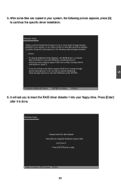
... diskette 1 into Drive A: * Press ENTER when ready Enter=Continue ESC=Cancel F3=Exit 91 It will load support for the following picture appears, press [S] to manually specify an adapter. Windows Setup Setup could not determine the type of one or more mass storage devices installed in your system, the following mass...
... diskette 1 into Drive A: * Press ENTER when ready Enter=Continue ESC=Cancel F3=Exit 91 It will load support for the following picture appears, press [S] to manually specify an adapter. Windows Setup Setup could not determine the type of one or more mass storage devices installed in your system, the following mass...


