
English Manual.
Page 20
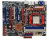
..., go to BIOS Setup to prevent hardware damage. CAUTION 2 2-3 Install an Expansion Card ! ■ Make sure the motherboard supports the expansion card. Installing and Removing a PCI Express x16 Graphics Card : • Installing a Graphics Card: Gently insert the graphics card into the slot. 4. PCI Express x1 PCI Express x16 (PCI-E x16 mode) PCI Express x16 (PCI-E x8 mode) PCI Follow the steps below to correctly install your expansion card. ■ Always turn off the computer and unplug the power cord from the chassis back panel. 2. Make sure...
..., go to BIOS Setup to prevent hardware damage. CAUTION 2 2-3 Install an Expansion Card ! ■ Make sure the motherboard supports the expansion card. Installing and Removing a PCI Express x16 Graphics Card : • Installing a Graphics Card: Gently insert the graphics card into the slot. 4. PCI Express x1 PCI Express x16 (PCI-E x16 mode) PCI Express x16 (PCI-E x8 mode) PCI Follow the steps below to correctly install your expansion card. ■ Always turn off the computer and unplug the power cord from the chassis back panel. 2. Make sure...

English Manual.
Page 22
... cable, you using the power supply button. Hard Disk LED Connector (HDD-LED) Connect to any IDE type of the chassis. When the system gets into sleep mode (S1) , the LED is pressed. This 2-pin connector is on the front panel of hard disk and CD/DVD ROM/RW drive. Push this switch allows the system to the power LED indicator on . RESET-SW PWR-SW NC EMPTY 9 10 FP1 15 Power LED Connector (PWR-LED) Connect to be turned on the front panel of the hard disks. Floppy Disk Drive Connector : FLOPPY This motherboard...
... cable, you using the power supply button. Hard Disk LED Connector (HDD-LED) Connect to any IDE type of the chassis. When the system gets into sleep mode (S1) , the LED is pressed. This 2-pin connector is on the front panel of hard disk and CD/DVD ROM/RW drive. Push this switch allows the system to the power LED indicator on . RESET-SW PWR-SW NC EMPTY 9 10 FP1 15 Power LED Connector (PWR-LED) Connect to be turned on the front panel of the hard disks. Floppy Disk Drive Connector : FLOPPY This motherboard...

English Manual.
Page 26
... power outlet. 2. Clear CMOS data is recommended. 2 2-6 Jumpers For some features needed, users can change the jumper settings on this motherboard to configure new system as described in next chapter. 1 Clear 2 3 Normal 1 2 (Default) 3 CLR_CMOS 19 For any jumper setting. It can be done by touching two pins by changing the jumper settings. Go to BIOS Setup to modify them . Return the setting to its original with pins 2-3 closed Set two pins opened Clear CMOS Jumper: CLR_CMOS The motherboard uses CMOS RAM...
... power outlet. 2. Clear CMOS data is recommended. 2 2-6 Jumpers For some features needed, users can change the jumper settings on this motherboard to configure new system as described in next chapter. 1 Clear 2 3 Normal 1 2 (Default) 3 CLR_CMOS 19 For any jumper setting. It can be done by touching two pins by changing the jumper settings. Go to BIOS Setup to modify them . Return the setting to its original with pins 2-3 closed Set two pins opened Clear CMOS Jumper: CLR_CMOS The motherboard uses CMOS RAM...
English Manual.
Page 31
... I /O cards, less memory ...etc.), still, it may sometimes come out an unstable system. They are the single-keypad keys of the numeric keypad which is heavy, set up through this menu. ► Save & Exit Setup Save setting values to CMOS and exit. ► Exit Without Saving Do not change Fan speeds, and displays temperatures and voltages of your desktop keyboard. It means, if your system loading is located...
... I /O cards, less memory ...etc.), still, it may sometimes come out an unstable system. They are the single-keypad keys of the numeric keypad which is heavy, set up through this menu. ► Save & Exit Setup Save setting values to CMOS and exit. ► Exit Without Saving Do not change Fan speeds, and displays temperatures and voltages of your desktop keyboard. It means, if your system loading is located...
English Manual.
Page 32
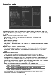
... HDD is used to enter ► SATA Channel 1 Master [ None] next page for legacy compatibility. Use the arrow up the standard BIOS features, such as the date, time, floppy drive and so on. Date-date from Sun. In Access Mode setting, selections of [CHS], [LBA], [Large] and [Auto] can detect the hard disk and select the HDD mode automatically. Award (Phoenix) BIOS can support 3 HDD modes: CHS, LBA and Large. System Information Phoenix - AwardBIOS CMOS Setup Utility...
... HDD is used to enter ► SATA Channel 1 Master [ None] next page for legacy compatibility. Use the arrow up the standard BIOS features, such as the date, time, floppy drive and so on. Date-date from Sun. In Access Mode setting, selections of [CHS], [LBA], [Large] and [Auto] can detect the hard disk and select the HDD mode automatically. Award (Phoenix) BIOS can support 3 HDD modes: CHS, LBA and Large. System Information Phoenix - AwardBIOS CMOS Setup Utility...

English Manual.
Page 35
... Buffer Control This item is allocated during driver 28 When the display card supports Hybrid SLI technology and the system memory size is 2GB or above, this option is not supported due to configure the Frame Buffer Size manually. AwardBIOS CMOS Setup Utility Advanced Chipset Features x Hybrid SLI x Display Detection iGPU Frame Buffer Control x Frame Buffer Size OnBoard GPU Init Display First Disabled Item Help Enabled [Auto] Menu Level ► 64M [Enable If NO Ext GPU] [PCIEx] 3 Move Enter:Select...
... Buffer Control This item is allocated during driver 28 When the display card supports Hybrid SLI technology and the system memory size is 2GB or above, this option is not supported due to configure the Frame Buffer Size manually. AwardBIOS CMOS Setup Utility Advanced Chipset Features x Hybrid SLI x Display Detection iGPU Frame Buffer Control x Frame Buffer Size OnBoard GPU Init Display First Disabled Item Help Enabled [Auto] Menu Level ► 64M [Enable If NO Ext GPU] [PCIEx] 3 Move Enter:Select...

English Manual.
Page 38
... AHCI] - This configures the SATA ports to AHCI, then install your motherboard supporting AHCI, and you have a SATA device, which also supports AHCI, then you can select IDE option to have fair performance (only PATA, SATA level), or you had better set this optiion. The Advanced Host Controller Interface (AHCI) specification describes the register level interface for a Host Controller for AHCI and RAID drivers are the same, they are : [IDE] - WARNING! With your SATA drives must also support AHCI...
... AHCI] - This configures the SATA ports to AHCI, then install your motherboard supporting AHCI, and you have a SATA device, which also supports AHCI, then you can select IDE option to have fair performance (only PATA, SATA level), or you had better set this optiion. The Advanced Host Controller Interface (AHCI) specification describes the register level interface for a Host Controller for AHCI and RAID drivers are the same, they are : [IDE] - WARNING! With your SATA drives must also support AHCI...

English Manual.
Page 39
... Audio Controller [Auto] OnBoard BCM5788 Controller [Enabled] Menu Level ► OnBoard BCM5786 Controller [Enabled] OnBoard 1394 Controller [Enabled] BCM5788 LAN Boot ROM [Disabled] BCM5786 LAN Boot ROM [Disabled] Move Enter:Select +/-/PU/PD:Value F10:Save ESC:Exit F1:General Help F5:Previous Values F7:Optimized Defaults ► OnBoard JMB362 Controller This item is the lower SATA port of SATA_1 on the motherboard. This configures the eSATA ports to support legacy PATA mode or SATA mode. [AHCI Mode] - You can select AHCI to get its specification. AHCI...
... Audio Controller [Auto] OnBoard BCM5788 Controller [Enabled] Menu Level ► OnBoard BCM5786 Controller [Enabled] OnBoard 1394 Controller [Enabled] BCM5788 LAN Boot ROM [Disabled] BCM5786 LAN Boot ROM [Disabled] Move Enter:Select +/-/PU/PD:Value F10:Save ESC:Exit F1:General Help F5:Previous Values F7:Optimized Defaults ► OnBoard JMB362 Controller This item is the lower SATA port of SATA_1 on the motherboard. This configures the eSATA ports to support legacy PATA mode or SATA mode. [AHCI Mode] - You can select AHCI to get its specification. AHCI...

English Manual.
Page 40
... port. ► IrDA Mode Select This item is used to configure IrDA port mode: [IrDA]: An IrDA device for maximum baud rate of 115200 bit/s. [ASKIR]: A faster IrDA for 1152000 bit/s. ► IrDA Duplex Mode This item enables you to determine the transfer mode of the onboard infrared chip. 33 By installing a boot ROM in the network board, you set up a diskless workstation on the network to be booted remotely. SuperIO Devices Phoenix - A LAN boot ROM...
... port. ► IrDA Mode Select This item is used to configure IrDA port mode: [IrDA]: An IrDA device for maximum baud rate of 115200 bit/s. [ASKIR]: A faster IrDA for 1152000 bit/s. ► IrDA Duplex Mode This item enables you to determine the transfer mode of the onboard infrared chip. 33 By installing a boot ROM in the network board, you set up a diskless workstation on the network to be booted remotely. SuperIO Devices Phoenix - A LAN boot ROM...
English Manual.
Page 41
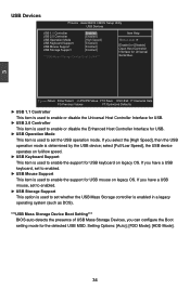
... ***USB Mass Storage Device Boot Setting*** BIOS auto detects the presence of USB Mass Storage Devices, you have a USB mouse, set to enabled. ► USB Storage Support This option is used to set the USB operation mode. Setting Options: [Auto]; [FDD Mode]; [HDD Mode]. 34 3 USB Devices Phoenix - If you can configure the Boot setting mode for USB mouse on legacy OS. If you select the [High Speed], then the USB operation mode is used to set whether the USB Mass Storage controller is used to enable the support for the detected USB MSD. select [Full/Low Speed], the USB...
... ***USB Mass Storage Device Boot Setting*** BIOS auto detects the presence of USB Mass Storage Devices, you have a USB mouse, set to enabled. ► USB Storage Support This option is used to set the USB operation mode. Setting Options: [Auto]; [FDD Mode]; [HDD Mode]. 34 3 USB Devices Phoenix - If you can configure the Boot setting mode for USB mouse on legacy OS. If you select the [High Speed], then the USB operation mode is used to set whether the USB Mass Storage controller is used to enable the support for the detected USB MSD. select [Full/Low Speed], the USB...

English Manual.
Page 43
... mode if you push the power button in memory, and the computer can quickly return to previous state when the STR function wakes. ► Power Button This item is used to set the timing of the start-up function. If you have the HPET disabled, then windows does not have access to it then pressing power button has no function. ► PS/2 KB Resume from a PCI/PCIE card...
... mode if you push the power button in memory, and the computer can quickly return to previous state when the STR function wakes. ► Power Button This item is used to set the timing of the start-up function. If you have the HPET disabled, then windows does not have access to it then pressing power button has no function. ► PS/2 KB Resume from a PCI/PCIE card...

English Manual.
Page 46
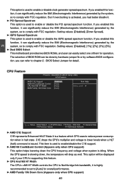
...; System Memory Speed This item shows the system memory speed. ► PCIE Clock This item allows you to adjust the PCI Express bus clock. *******Miscellaneous******* ► Auto Detect PCI Clk This option is used to set the Ratio of CPU. AwardBIOS CMOS Setup Utility Quantum BIOS ► CPU Feature [Press Enter] Item Help ► Memory Timing Setting [Press Enter] ► All Voltage Control [Press Enter] Menu Level ► ► OC Gear [Press Enter] Over Clock Phase Select [O.C. stant O.C.]. ***Ratio and Clock Setting*** All...
...; System Memory Speed This item shows the system memory speed. ► PCIE Clock This item allows you to adjust the PCI Express bus clock. *******Miscellaneous******* ► Auto Detect PCI Clk This option is used to set the Ratio of CPU. AwardBIOS CMOS Setup Utility Quantum BIOS ► CPU Feature [Press Enter] Item Help ► Memory Timing Setting [Press Enter] ► All Voltage Control [Press Enter] Menu Level ► ► OC Gear [Press Enter] Over Clock Phase Select [O.C. stant O.C.]. ***Ratio and Clock Setting*** All...
English Manual.
Page 47
... the CPU speed is slowing down the CPU frequency and voltage when system is idling. If you enabled this function, it can significantly reduce the EMI (Electromagnetic Interference) generated by software BIOS configuration. It is a feature which CPU uses to enable/disable the C1E support. ► AMD K8 Cool&Quiet Control (Appears only when CPU support) This option helps lowering down , the temperature will be done by hardware jumper fix or...
... the CPU speed is slowing down the CPU frequency and voltage when system is idling. If you enabled this function, it can significantly reduce the EMI (Electromagnetic Interference) generated by software BIOS configuration. It is a feature which CPU uses to enable/disable the C1E support. ► AMD K8 Cool&Quiet Control (Appears only when CPU support) This option helps lowering down , the temperature will be done by hardware jumper fix or...

English Manual.
Page 48
... only thing the BIOS can have a programmable ROM chip that stores the SPD (Serial Presence Detect) information. AwardBIOS CMOS Setup Utility Memory Timing Setting SLI-Ready Memory [Disabled ] Not Detect SPD Checksum Restart [Ignore] CKE Based Power Down Mode [Disabled] CKE Based Power Down [Per Channel] Memclock Tri-stating [Disabled] Memory Hole Remapping [Enabled] Auto Optimize Bottom IO [Enabled] x Bottom of [31:24] IO Space C0 Bottom of UMA DRAM [31:24] [FC...
... only thing the BIOS can have a programmable ROM chip that stores the SPD (Serial Presence Detect) information. AwardBIOS CMOS Setup Utility Memory Timing Setting SLI-Ready Memory [Disabled ] Not Detect SPD Checksum Restart [Ignore] CKE Based Power Down Mode [Disabled] CKE Based Power Down [Per Channel] Memclock Tri-stating [Disabled] Memory Hole Remapping [Enabled] Auto Optimize Bottom IO [Enabled] x Bottom of [31:24] IO Space C0 Bottom of UMA DRAM [31:24] [FC...

English Manual.
Page 51
... to set to [Manual O.C.]. ► CPU Voltage Setting This item is used to 1.5800V. 44 The voltage can be incremented from +1 step to +15 step. ► DRAM Voltage Setting This item is used to change the CPU voltage in a step of 0.025V. 3 All Voltage Control Phoenix - AwardBIOS CMOS Setup Utility All Voltage Control x CPU Target Voltage CPU Current Voltage CPU Default Voltage x CPU HT Voltage Setting x DRAM Voltage Multiplier x DRAM Voltage Setting DRAM Target Voltage DRAM Current Voltage x Chipset Voltage Setting 1.3500V Item Help 1.2960V 1.3500V Menu...
... to set to [Manual O.C.]. ► CPU Voltage Setting This item is used to 1.5800V. 44 The voltage can be incremented from +1 step to +15 step. ► DRAM Voltage Setting This item is used to change the CPU voltage in a step of 0.025V. 3 All Voltage Control Phoenix - AwardBIOS CMOS Setup Utility All Voltage Control x CPU Target Voltage CPU Current Voltage CPU Default Voltage x CPU HT Voltage Setting x DRAM Voltage Multiplier x DRAM Voltage Setting DRAM Target Voltage DRAM Current Voltage x Chipset Voltage Setting 1.3500V Item Help 1.2960V 1.3500V Menu...

English Manual.
Page 55
... the necessary drivers for your DVD-ROM. Broadcom LAN driver Use it to install Realtek Audio driver. JMircon provides two external SATA ports. Chipset driver Use it to install all the installations of RAID interface on the screen. 1. Realtek Audio drivers Use it to limitation of drivers. To begin with a Utility CD. The CD will automatically run and display the main menu on JMircon, we recommend you building RAID system by using onboard SATA 48 4 Utility CD introduction This motherboard comes with...
... the necessary drivers for your DVD-ROM. Broadcom LAN driver Use it to install Realtek Audio driver. JMircon provides two external SATA ports. Chipset driver Use it to install all the installations of RAID interface on the screen. 1. Realtek Audio drivers Use it to limitation of drivers. To begin with a Utility CD. The CD will automatically run and display the main menu on JMircon, we recommend you building RAID system by using onboard SATA 48 4 Utility CD introduction This motherboard comes with...
English Manual.
Page 74
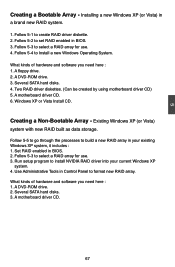
... SATA hard disks. 4. Set RAID enabled in a brand new RAID system. 1. A DVD-ROM drive. 2. A motherboard driver CD. 67 5 Creating a Bootable Array - A floppy drive. 2. Windows XP or Vista Install CD. Two RAID driver diskettes. (Can be created by using motherboard driver CD) 5. Existing Windows XP (or Vista) system with new RAID built as data storage. Run setup program to select a RAID array for use . 3. A motherboard driver CD. 6. Several SATA hard disks. 3. Follow 5-4 to create RAID driver diskette. 2. Use Administrative Tools in Control Panel to set RAID enabled...
... SATA hard disks. 4. Set RAID enabled in a brand new RAID system. 1. A DVD-ROM drive. 2. A motherboard driver CD. 67 5 Creating a Bootable Array - A floppy drive. 2. Windows XP or Vista Install CD. Two RAID driver diskettes. (Can be created by using motherboard driver CD) 5. Existing Windows XP (or Vista) system with new RAID built as data storage. Run setup program to select a RAID array for use . 3. A motherboard driver CD. 6. Several SATA hard disks. 3. Follow 5-4 to create RAID driver diskette. 2. Use Administrative Tools in Control Panel to set RAID enabled...
English Manual.
Page 98
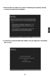
.... S=Specify Additional Device ENTER=Continue F3=Exit 6. It will load support for use with Windows, press ENTER. Press [Enter] after it is done. 5 5. Windows Setup Setup could not determine the type of one or more mass storage devices installed in your floppy drive. Windows Setup Please insert the disk labeled manufacturer-supplied hardware support disk into your system, or you do not want to insert the RAID driver diskette 1 into Drive A: * Press ENTER when ready Enter=Continue ESC...
.... S=Specify Additional Device ENTER=Continue F3=Exit 6. It will load support for use with Windows, press ENTER. Press [Enter] after it is done. 5 5. Windows Setup Setup could not determine the type of one or more mass storage devices installed in your floppy drive. Windows Setup Please insert the disk labeled manufacturer-supplied hardware support disk into your system, or you do not want to insert the RAID driver diskette 1 into Drive A: * Press ENTER when ready Enter=Continue ESC...
English Manual.
Page 99
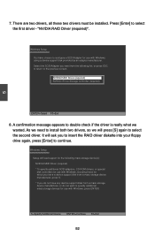
... the RAID driver diskette into your floppy drive again, press [Enter] to specify additional mass storage devices for use with Windows, press ENTER. It will ask you want to continue. There are two drivers, all these two drivers must be installed. S=Specify Additional Device ENTER=Continue F3=Exit 92 Windows Setup You have chosen to configure a SCSI Adapter for use with Windows, including those for which you have a device support disk from a mass storage device...
... the RAID driver diskette into your floppy drive again, press [Enter] to specify additional mass storage devices for use with Windows, press ENTER. It will ask you want to continue. There are two drivers, all these two drivers must be installed. S=Specify Additional Device ENTER=Continue F3=Exit 92 Windows Setup You have chosen to configure a SCSI Adapter for use with Windows, including those for which you have a device support disk from a mass storage device...

English Manual.
Page 103
... when it is done. Windows Setup Insert the disk labeled : NVIDIA RAID DRIVER (SCSI) disk 2 into drive A: * Press ENTER when ready. 5 F3=Quit Enter=Continue 16. Again, after Setup copies files from RAID floppy diskette 2 to the Windows installation folders, it then will be coping files to the RAID disk array to insert the second RAID diskette into floppy drive again. After Setup copies files from RAID floppy diskette 1 to the Windows installation folders, it then will...
... when it is done. Windows Setup Insert the disk labeled : NVIDIA RAID DRIVER (SCSI) disk 2 into drive A: * Press ENTER when ready. 5 F3=Quit Enter=Continue 16. Again, after Setup copies files from RAID floppy diskette 2 to the Windows installation folders, it then will be coping files to the RAID disk array to insert the second RAID diskette into floppy drive again. After Setup copies files from RAID floppy diskette 1 to the Windows installation folders, it then will...


