
English Manual.
Page 6
...Install the Memory 11 Install an Expansion Card 13 Install other Internal Connectors 14 Jumpers 17 Chapter 3 BIOS Setup Enter BIOS Setup 20 Main Menu 20 System Information 22 Advanced BIOS Features 24 Fox Central Control Unit 26 Advanced Chipset Features 29 Integrated Peripherals 33 Power Management Setup...Save & Exit Setup 41 Exit Without Saving 41 Chapter 4 CD Instruction Utility CD content 43 Install driver and utility 44 FOX ONE Main Page 46 CPU Control 50 Frequency Control 52 Limit Setting 53 Voltage Control 55 Fan Control 56 FOX LiveUpdate Local Update 57 Online ...
...Install the Memory 11 Install an Expansion Card 13 Install other Internal Connectors 14 Jumpers 17 Chapter 3 BIOS Setup Enter BIOS Setup 20 Main Menu 20 System Information 22 Advanced BIOS Features 24 Fox Central Control Unit 26 Advanced Chipset Features 29 Integrated Peripherals 33 Power Management Setup...Save & Exit Setup 41 Exit Without Saving 41 Chapter 4 CD Instruction Utility CD content 43 Install driver and utility 44 FOX ONE Main Page 46 CPU Control 50 Frequency Control 52 Limit Setting 53 Voltage Control 55 Fan Control 56 FOX LiveUpdate Local Update 57 Online ...
English Manual.
Page 9
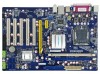
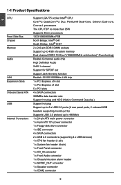
... Support up to 8 x USB 2.0 ports (4 rear panel ports, 2 onboard USB headers supporting 4 extra ports) Supports USB 2.0 protocol up to 480Mb/s Internal Connectors 1 x 24-pin ATX main power connector 1 x 4-pin ATX 12V power connector 1 x Floppy disk drive connector 1 x IDE connector 4 x SATA connectors 2 x USB 2.0 connectors (supporting 4 x USB devices) 1 x CPU fan header (4-pin) 1 x System...
... Support up to 8 x USB 2.0 ports (4 rear panel ports, 2 onboard USB headers supporting 4 extra ports) Supports USB 2.0 protocol up to 480Mb/s Internal Connectors 1 x 24-pin ATX main power connector 1 x 4-pin ATX 12V power connector 1 x Floppy disk drive connector 1 x IDE connector 4 x SATA connectors 2 x USB 2.0 connectors (supporting 4 x USB devices) 1 x CPU fan header (4-pin) 1 x System...

English Manual.
Page 22
.../2/3/4 SPKJ EMPTY NC SPKJ SPEAKER 2 PORT1_L PORT1_R PORT2_R SENSE_SEND PORT2_L 12 9 10 AUD_GND PRESENCEJ SENSE1_RETURN EMPTY SENSE2_RETURN F_AUDIO Fan Connectors : CPU_FAN, SYS_FAN There are two main fan headers on this feature. The current Serial ATA II interface allows up to connect speaker of the BIOS Setup. Serial ATA Connectors : SATA_1/2/3/4 The...
.../2/3/4 SPKJ EMPTY NC SPKJ SPEAKER 2 PORT1_L PORT1_R PORT2_R SENSE_SEND PORT2_L 12 9 10 AUD_GND PRESENCEJ SENSE1_RETURN EMPTY SENSE2_RETURN F_AUDIO Fan Connectors : CPU_FAN, SYS_FAN There are two main fan headers on this feature. The current Serial ATA II interface allows up to connect speaker of the BIOS Setup. Serial ATA Connectors : SATA_1/2/3/4 The...

English Manual.
Page 26
You have to run the Setup Program when the following information : ■ Enter BIOS Setup ■ Main Menu ■ System Information ■ Advanced BIOS Features ■ Fox Central Control Unit ■ Advanced Chipset Features ■ Integrated Peripherals ■ Power Management Setup ■ ...
You have to run the Setup Program when the following information : ■ Enter BIOS Setup ■ Main Menu ■ System Information ■ Advanced BIOS Features ■ Fox Central Control Unit ■ Advanced Chipset Features ■ Integrated Peripherals ■ Power Management Setup ■ ...

English Manual.
Page 27
...:Save ESC:Exit F1:General Help F9:Optimized Defaults Configure Time and Date. v02.63 (c) Copyright 1985-2008, American Megatrends, Inc. Main Menu The main menu allows you to maintain optimal system performance. CMOS Setup Utility - Display System Information... Each item in the BIOS Setup, and we... shall not be set up the BIOS parameters is critical to select from the change you change the default values in the main menu is explained below: ► System Information It displays the basic system configuration, such as Serial I /O devices such as BIOS version...
...:Save ESC:Exit F1:General Help F9:Optimized Defaults Configure Time and Date. v02.63 (c) Copyright 1985-2008, American Megatrends, Inc. Main Menu The main menu allows you to maintain optimal system performance. CMOS Setup Utility - Display System Information... Each item in the BIOS Setup, and we... shall not be set up the BIOS parameters is critical to select from the change you change the default values in the main menu is explained below: ► System Information It displays the basic system configuration, such as Serial I /O devices such as BIOS version...

English Manual.
Page 37
... enable/disable provision of system memory used by internal graphics device. ► PEG Port This item is used to enable/disable memory remap feature. Its mainly for SPD enable mode. Copyright (C) 1985-2008, American Megatrends, Inc. It contains important information about the module's speed, size, addressing mode and various other parameters...
... enable/disable provision of system memory used by internal graphics device. ► PEG Port This item is used to enable/disable memory remap feature. Its mainly for SPD enable mode. Copyright (C) 1985-2008, American Megatrends, Inc. It contains important information about the module's speed, size, addressing mode and various other parameters...

English Manual.
Page 48
... will be displayed in the center of the screen: Select [OK] to exit CMOS without saving your modifications, select [Cancel] or to return to the main menu. Select and press , it will pop out a dialogue box to load the defaults. Save & Exit Setup When you select this motherboard. 3 Load Optimal Defaults... select this default, BIOS have set cannot be supported by your changes to CMOS and exit the program, select [Cancel] or to return to the main menu. Discard changes and exit setup? [OK] [Cancel] 41
... will be displayed in the center of the screen: Select [OK] to exit CMOS without saving your modifications, select [Cancel] or to return to the main menu. Select and press , it will pop out a dialogue box to load the defaults. Save & Exit Setup When you select this motherboard. 3 Load Optimal Defaults... select this default, BIOS have set cannot be supported by your changes to CMOS and exit the program, select [Cancel] or to return to the main menu. Discard changes and exit setup? [OK] [Cancel] 41
English Manual.
Page 50
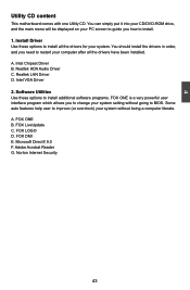
... B. FOX LOGO D. 4 Utility CD content This motherboard comes with one Utility CD. You can simply put it into your CD/DVD-ROM drive, and the main menu will be displayed on your PC screen to guide you how to improve (or overclock) your computer after all the drivers for your system...
... B. FOX LOGO D. 4 Utility CD content This motherboard comes with one Utility CD. You can simply put it into your CD/DVD-ROM drive, and the main menu will be displayed on your PC screen to guide you how to improve (or overclock) your computer after all the drivers for your system...

English Manual.
Page 53
... bar (i.e. Alert Lamp When the system is in abnormal state, the alert lamp color is green. Simple Mode) as depicted below, you monitoring system status. Main Page Show CPU Information Toolbar Alert Lamp 4 Monitor Frequency/Voltage/Fan speed/Temperature value Switch Button Skin Button Exit Minimum Configuration Homepage Toolbar Use the...
... bar (i.e. Alert Lamp When the system is in abnormal state, the alert lamp color is green. Simple Mode) as depicted below, you monitoring system status. Main Page Show CPU Information Toolbar Alert Lamp 4 Monitor Frequency/Voltage/Fan speed/Temperature value Switch Button Skin Button Exit Minimum Configuration Homepage Toolbar Use the...

English Manual.
Page 72
...; Windows 2003 (32-bit and 64-bit) ■ Windows Vista (32-bit and 64-bit) ■ Windows 7 (32-bit/64-bit) Using FOX LOGO: Main Page Main screen Backup Change Delete Exit Minimize Website About WARNING! You can prepare a JPG image (1024x768) file, then use FOX LOGO to backup, change and delete...
...; Windows 2003 (32-bit and 64-bit) ■ Windows Vista (32-bit and 64-bit) ■ Windows 7 (32-bit/64-bit) Using FOX LOGO: Main Page Main screen Backup Change Delete Exit Minimize Website About WARNING! You can prepare a JPG image (1024x768) file, then use FOX LOGO to backup, change and delete...